Mathematical approach of fiber optics for renewable energy sources using general adversarial networks
 Tawfiq Hasanin1
  Hariprasath Manoharan2*
  Hassan A. Alterazi3
  Gautam Srivastava4,5,6
  Shitharth Selvarajan7
  Jerry Chun-Wei Lin8*
- 1Department of Information Systems, Faculty of Computing and Information Technology, King Abdulaziz University, Jeddah, Saudi Arabia
- 2Department of Electronics and Communication Engineering, Panimalar Engineering College, Chennai, India
- 3Department of Information Technology, Faculty of Computing and Information Technology, King Abdulaziz University, Jeddah, Saudi Arabia
- 4Department of Mathematics and Computer Science, Brandon University, Brandon, MB, Canada
- 5Research Centre for Interneural Computing, China Medical University, Taichung, Taiwan
- 6Department of Computer Science and Mathematics, Lebanese American University, Beirut, Lebanon
- 7Department of Computer Science and Engineering, Kebri Dehar University, Kebri Dahar, Ethiopia
- 8Department of Applied Science, Western Norway University of Applied Sciences, Bergen, Norway
It is significantly more challenging to extend the visibility factor to a higher depth during the development phase of a communication system for subterranean places. Even if there are numerous optical fiber systems that provide the right energy sources for intended panels, the visibility parameter is not optimized past a certain point. Therefore, the suggested method looks at the properties of a fiber optic communication system that is integrated with a certain energy source while having external panels. A regulating state is established in addition to characteristic analysis by minimizing the reflection index, and the integration of the general adversarial network (GAN) optimizes both central and layer formations in exterior panels. Thus, the suggested technique uses the external noise factor to provide relevant data to the control center via fiber optic shackles. As a result, the normalized error is smaller, boosting the suggested method's effectiveness in all subsurface areas. The created mathematical model is divided into five different situations, and the results are simulated using MATLAB to test the effectiveness of the anticipated strategy. Additionally, comparisons are done for each of the five scenarios, and it is found that the proposed fiber-optic method for energy sources is far more effective than current methodologies.
1. Existing approaches
To recognize every experimental setting and the fundamental fiber optic configuration, some of the pertinent present methodologies are discussed next. A significant support for renewable energy sources is mentioned, along with improvement factors in addition to fiber optic configuration systems, since the design models of these sources play a significant role in optical system communication. In order to create a solid configuration system, it is necessary to evaluate the majority of contemporary literature that offers useful insight into integration patterns. Nano scaling features are used to specify several machine learning algorithms in Jin et al. (2020) that enhance automatic support for optical communication systems. When an optical system is modeled on the Nano scale, all subsurface visibility patterns must be improved. However, Nano scale materials restrict 20% of the visibility of all accessible energy sources due to non-linear extenuation. To address the issue of Nano scaling, a reconfigurable meta device with a suitable mathematical description is thus introduced (Venketeswaran et al., 2022). The researchers used a direct complex matrix to configure the meta device in order to reduce the amount of loss and errors in fiber optic communication. However, while direct representation approaches offer a fully customizable system, the majority of faults in communication channel segments remain unclear. In order to improve the performance of energy resources, it is always crucial to provide sustainable communication in underground spaces (Mata et al., 2018). As a result, a routing technique using system-on-chip technology is introduced. Due to the use of routing techniques, the complexity of the entire fiber optics space is reduced, and the indoor environment is changed to make the system more energy-efficient.
Numerous precautions are required to prevent changes in indoor environments because subsurface areas will have additional challenges as a result of changing environmental conditions (Padmapriya, 2021). Therefore, non-linear operations are used in distributed operations, and they are directly utilized in deformation areas. Due to these applications, fiber optics' effectiveness for energy sources is enhanced, and even the entire phase of optical networks can change in some ways. Some simulations are inserted directly in the indoor channel (Wassin et al., 2018) as an alternative to distributed operations, and in these simulations, the energy delivered to energy resources is drastically decreased. The precision of the transfer function across the board is increased due to the reduction in energy sources, and diffused channels are eliminated throughout the augmentation process. However, the lack of a replacement option for diffused channels drives up the cost of implementation when using the direct line of sight method. Additional couplings must be employed when designing fiber optic systems to prevent reflective index so that any changes in angle deviation can be detected (Obukhov et al., 2018). Solar light panels can be used in conjunction with directed couples to record changes in deviation, which improves the visibility pattern. However, the application arrangement varies since couples are employed in the construction of some homes, which is not a serious issue that needs to be examined. The majority of energy resources will operate directly in subsurface areas thanks to wireless sensor networks, and if any faults are found, the entire system can be switched to a distributed mode of operation (Sánchez et al., 2020). The aforementioned procedure is completed automatically using the least squares algorithm, which increases data on the generation of energy sources. Even now, the least-squares integration process with energy sources is not clearly specified, and the automatic vicinity is reduced as a result of the amorphous design pattern.
Some Internet Protocols are introduced using wavelength-specified optical networks in a novel approach to improving optical networks' training (Nevin et al., 2021). Every time, the protocol methods must be changed under specific restrictions; however, essential design changes can be made in accordance with subsurface areas. When fiber optics and energy sources with diverse patterns are coupled, it is challenging to install the changing procedures in real-time situations. However, line-of-sight arrangements are used to test the effectiveness of transmitting optical networks in order to adapt to the changing process pattern (Kribus et al., 2000). All optical loop configuration limits are improved with this type of testing; however, significant factors relating to parametric lengths remain unchanged. More physical configuration damage will consequently result, which has an impact on the transmission length of optical cables. It is indicated that generated power must be delivered in proper proportion in order to protect the planned system from physical degradation (Rosa et al., 2022). Even though some standard parameters for fiber optic power generation have been established, the supplied power in some cases remains stable for the duration of the installation cycle. As a result, only asymptotic assumptions may be made during the generating process, and no adjustments can be made after installation. By establishing proper transceivers, optical networks may also transfer data (Schöndienst and Vokkarane, 2014). Even at this point, existing optical equipment can be easily modified. It is advised to add additional power to energy resources that are processed using external panels during the reconfiguration stage because this will have an impact on the overall efficiency cycle.
Additionally, some mathematical approaches—which are based solely on data already present for fiber optic communications—are created to ensure steady functioning during the entire process (Aslian et al., 2016; Nengroo et al., 2022). All fiber optic and energy source integration cannot be carried out in real time by using related datasets alone because various optimization techniques are required. As a result, wireless communication methods based on polarization are being developed for networks that will produce data results considerably more quickly (Schulze, 2018; Teng et al., 2022). All problems are recorded, and the external panels are adequately coated and monitored due to the quick growth in data flow. The essential approach for the proposed method is provided by all of the aforementioned current methodologies as indicated in Table 1, and the corresponding system model is created in Section 2.
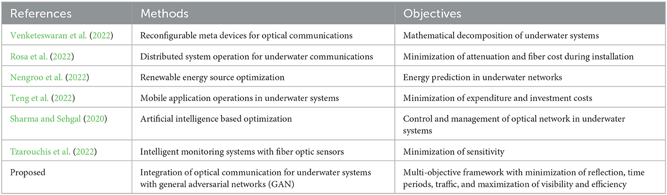
Table 1. Comparison with recent works.
1.1. Research gap and motivation
Many techniques are present for ensuring underwater management system by using several communication methodologies such as Nano scale Meta devices and autonomous robotic operations (Lin and Lai, 2015; Sharma and Sehgal, 2020; Tzarouchis et al., 2022). All autonomous operations provide some relevant information regarding the status of different operating characteristics that are present underwater which are directly related to distance measurements. However the underwater distance measurement alone cannot provide relevant information with respect to system technologies, thus resulting in failure of operational and monitoring cases. Additionally, the percentage of loss is much higher for designed existing systems due to instability in installing principles. Hence there is a need to provide an alternate design model using fiber optic representation systems that consists of minimized loss periods. In order to provide an alternate solution for monitoring underwater communication networks, the projected model incorporates an optical fiber network at a high visibility pattern. If the proposed system is integrated in real time, then it is possible to search all inner operations that are present in underwater networks where the reflection index at both primary and secondary layers is reduced. Due to reduced reflection pattern, it is observed that all classes of underwater living things are saved which provides additional advantages to designed operating conditions. Therefore, without any outstanding problems, the proposed method can be operated with proper link connection at low traffic conditions. Moreover, to reduce the loss that is caused by fiber optic communication networks, General Adversarial Networks (GAN) are integrated that provides true and false sample set values thus effective outcomes are achieved.
1.2. Objectives
The major contribution of the proposed system is to develop and integrate an underwater management system where the entire communication technique must be processed using low cost fiber optic communication with the following parametric objectives:
• Development of fiber optic communication using high visibility patterns under the sea water at low reflection index.
• Connect a clear transmission link that minimizes the noise parameter by ensuring low traffic conditions.
• Provide maximum efficient network at large scale using General Adversarial Networks (GAN) at reduced loss functions.
2. System model
When using optic fiber applications for renewable energy sources, it is critical that fiber insulation be delivered to a specific device at proper measures. The integrated device will remain in a low-protected condition if the measuring rate increases to a specified degree. Therefore, fundamental mathematical formulations are developed and installed for Renewable Energy Sources (RES) systems processing underwater in order to determine measurement. Additionally, the analytical model offers a thorough understanding of how optical fibers behave when operating with wireless networks, which gives the suggested technique a vibrant foundation. The aforementioned creation works by connecting optical couplers to external panels, which increases light visibility in the underground system. As a result, the mathematical model for panel intensification is provided in Equation (1).
where,
Ii(n), Ii(ci) denotes optic index of inner and solar coupler rays, respectively.
sinθin, sinθr represents instance optical angle of inner and refracted rays.
Equation (1) states that by utilizing angle indices, the subsurface visibility of an optic fiber in the sun must be improved. However, reflection from panels connected by optical fiber must be avoided by utilizing Equation (2), as shown below.
where,
sino(i) denotes angle for preventing reflection at output.
ωi, φi represents index of primary and secondary layers in panels, respectively.
Equation (2) shows that the layers offered to exterior panels must be provided in proper form to establish precise aperture for light to pass through at the proper extent. However, if the opening is significantly larger, reflection will once again be present in the system; therefore, rigorous testing must be done during the installation phase. Equation (3) will be used to test the transmission link once the light has passed between the various layers inside the panels.
where,
Tl, To describe the time taken for link connection and optimization, respectively.
Equation (3) illustrates the minimization problem for establishing adequate optical linkages and the optimization method needed to establish strong transmission in subterranean regions using installed panels. In order to prevent the panels from being impacted by any kind of backup system, the transmission power for optic links must be provided in an appropriate manner. Therefore, using Equation (4), it is necessary to turn off all unneeded layers in fiber optics.
where,
Tfi, Tfo represents optic traffic in installed panels.
wlt denotes corresponding optic wavelength.
Equation (4) describes the minimization problem of all traffic that exists in optical systems; hence, in subversive systems, full visibility of light will exist in the absence of traffic. The amount of radiation present in complete panels must also be reduced in order to increase the efficiency of optic fibers, which is expressed using Equation (5) as follows,
where,
poweri represents the generated optic power in panels.
αp denotes the accessible panel areas.
The generation of power must be flexible enough to operate, and there must be a reduction in additional supply cases in the optical networks in order to maximize the efficiency of all energy sources. Therefore, the proposed method incorporates a reverse selection mechanism by applying Equation (6), in order to reduce the additional power.
where,
τi denotes energy of forward path.
sinri represents angle of optic installation.
When all radiation is permitted to be processed exclusively in the forward direction, Equation (6) is created using a sine angle. Equation (7) can be used to express the entire efficiency of the optical network for an energy source as follows.
where,
TPi describes total power of optic shackles.
IP indicates total inlet power.
To improve the overall effectiveness of the network, the entire developed analytical framework is used in the design process of fiber optic energy sources, which is combined with optimization techniques.
All individual mathematical representations are made with respect to different parametric index values where individual characteristics are described. Hence the combined objective function can be framed using Equations (8, 9) as follows:
Both the above mentioned objective function will be integrated with GAN in order to connect the data set representation values thus efficiency of fiber optic operations will be maximized at minimized error values.
3. Optimization algorithm
Since the suggested technique calls for subterranean transmission operations, it is crucial to offer a powerful optical network-based data handling system. Thus, the General Adversarial Network (GAN), one of the most potent artificial intelligence (AI) algorithms, is integrated and adds some input noise to the data (Balamurugan et al., 2022; Karthikeyan et al., 2022; Onyema et al., 2022). The main benefit of GAN in optical communication is the ability to frame a new kind of optical vision for all kinds of energy sources. Additionally, feature learning mechanisms, which offer unrestricted training, can be used to implement all optical networks. Since no prior assumptions about an energy source are made, certain distributions arise that are present in all circumstances with an identical likelihood. Every time a GAN is applied to an optical network, a set of synthetic data is produced, examined, and utilized to minimize all training data. An original channel model must be constructed in order to offer free space communication throughout the entire subsurface, and employing GAN is the only way to do so because it creates effective communication channels as opposed to other optimization strategies. Therefore, it is necessary to minimize the loss function of the communication channel, which is expressed using Equation (10) as follows,
where,
Dt, Df describes data representation of true and false samples, respectively.
When regularization is required for all input data sets, which is represented by Equation (11), and Equation (10) is constructed as a minimization function for all input samples.
where,
Zi describes all input data set that provides modification between true and false values.
If the regularization parameter in Equation (11) is not maximized, there will be more mistakes in the optical system, which causes GAN to provide values with low consistency. The following formulation of Equation (12) must be used to generate normalized power with undercoat to external panels in order to prevent errors in fiber optics for energy resources,
where,
, Z0, Z2 denotes data generated, output data and square of input data respectively.
Equation (12), which is written as a minimization function, produces an arrangement map function by incorporating all required fiber channels. Thus, Figure 1 and Algorithm 1 clarify the arrangement.
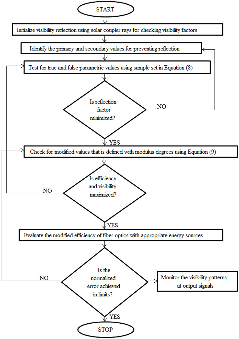
Figure 1. General adversarial network for fiber optics.
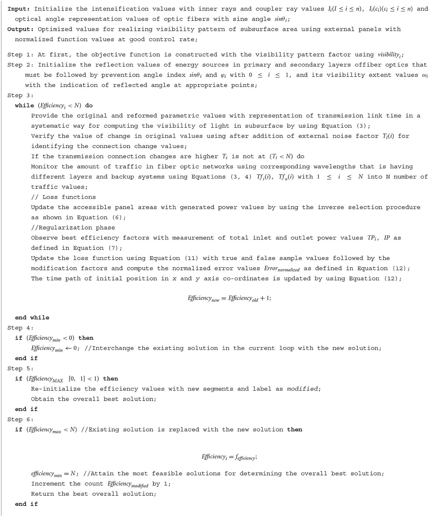
Algorithm 1. General Adversarial Network (GAN).
4. Results and discussions
Real-time experimental results are seen by using the hardware setup in a small subterranean region where the performance of both fiber optics and exterior preventing panels is assessed after integrating the proposed system model and optimization with GAN. The efficiency of the suggested method is significantly higher since energy dissipation and reflection characteristics are reduced thanks to the high closing capacity of external panels made possible by fiber optic insulation. The channel length is taken into account with a wavelength of 1,500 nanometers in order to observe relevant parameters in reality; hence, no modification in observation times is provided after the specified wavelength. In contrast, consistent measurements are taken at arbitrary times when there is high visibility in subterranean regions. Additionally, the covered central area is kept at 65 square meters, converting light visibility into a circle to make achieving the marginal boundary values simple. The quantity of noise in the optical signal is decreased for the aforementioned central area to 3 decibels, preventing any outside noise from getting into the optical communication systems. Inputs from several optical channels are gathered in order to construct the hardware arrangement, and performance is measured depending on the situations listed below.
Scenario 1: Intensification rate
Scenario 2: Reflection index
Scenario 3: Transmission link connection
Scenario 4: Modified efficiency
Scenario 5: Normalized error
4.1. Scenario 1
The visibility pattern in the subterranean area will improve as the intensity of the fiber optic network is reduced. In order to evaluate this scenario, the designed system's coupler beams are tested. The optical angle of the inner rays in the system is decreased since, throughout this inspection, the refracted rays are held at their minimal location. The variable sine angle is arranged in a proper sequence with an equal distribution of lengths as a result of this design approach. Some of the applicable energy sources will still make an effort to deliver more optical power with less storage even after equal distribution. In order to avoid the aforementioned scenario, the intensification rate is kept to a minimum, and inner couplers are used to separate the components. The optical index of inner angles is measured and replicated with direct inner wave application in the first phase. Once the index is kept at the lowest rate, separation with refracted and solar-coupled rays will begin. The simulation's results for intensification rate with good visibility in the subsurface area are shown in Figure 2.
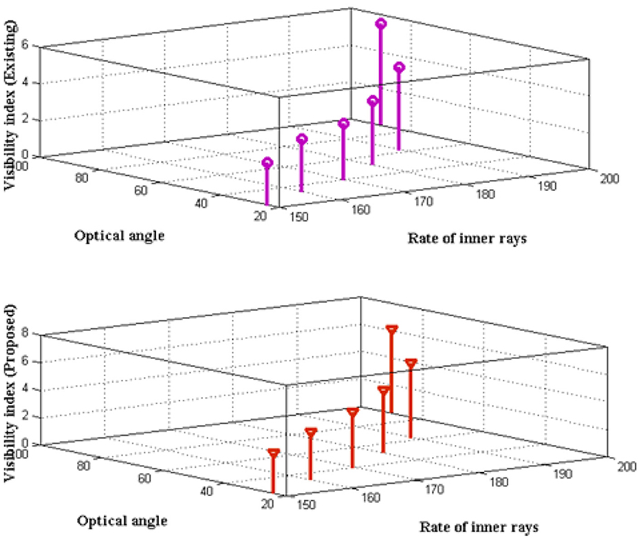
Figure 2. Visibility pattern beside inner rays.
Figure 2 and Table 2 show five distinct rates for inner rays between 150 and 200, with corresponding angle indices of 24, 33, 40, 51, 63, and 90. The visibility index is calculated and contrasted with the current method (Padmapriya, 2021) using the index mentioned above. In the comparison instance, the suggested strategy provides a highest visibility rate with the lowest intensity. In contrast to the existing case, the visibility pattern of insulated panels is much clearer when the maximization case is applied for all different rates and varying optical angles. This can be demonstrated using a rate of 180 and a measurement at a 51-degree angle, where 4.52 nanometer visibility is attained at subsurface locations but only 3.49 nanometers are visible using the current method. Therefore, even when using different angles, the suggested method offers the best separation rate, and even when using more external panels, it is still possible to make the visibility of light last for the longest possible time.
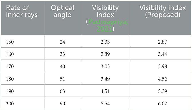
Table 2. Visibility index.
4.2. Scenario 2
Controlling the amount of reflection in fiber optics during the signal transmission phase is necessary to ensure proper communication with external panels without any interruptions. When reflection is being examined, it is crucial to keep an eye on both the primary and secondary shields because additional insulation will prevent reflection from occurring at the output. Reproductions of the primary and secondary panels are used to observe the reflective index output angles. The amount of reflection between the primary and secondary panels is measured at half angles during this calculation. As a result, the amount of reflection is significantly reduced without changing the direction in which fiber optic signals are induced. Making the waves return to their original position is crucial whenever adjustments are made to the measurement process. As a result, all fiber optic waves are freed from all kinds of light return paths, as shown in Figure 3.
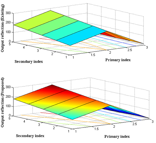
Figure 3. Reflection index with primary and secondary focus.
The primary and secondary index are realistically set at external panels with external separation, as shown in Figure 3 and Table 3. The primary and secondary indexes are separated by 20 points, with the primary index being fixed at 100 to 180 and the secondary index being regular from 200 to 280. The proportion of reflection is evaluated during these primary and secondary indices and compared to the current technique (Padmapriya, 2021). Comparison reveals that the proposed method's reflection index is significantly lower than that of the current instance, where roughly 1% of the index is guaranteed. The primary and secondary index of 160 and 260 respectively, with a percentage of output reflection of 9 for the existing method and 2 in the case of the current method, can be used to demonstrate the above-mentioned reflection index measurement. When the primary and secondary values rise, the reflecting index falls, preserving exactly the same input-side features. But if suitable sine angles are not reached at the output, the reflective index rises.
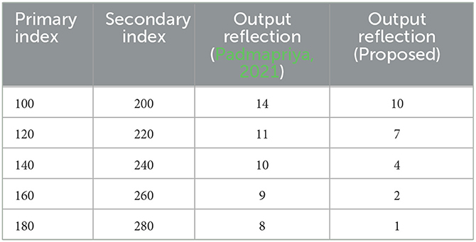
Table 3. Reflection at output.
4.3. Scenario 3
Before transmitting visible light deeply into the subsurface, whenever a fiber optic connection is made with energy resources that take the form of external panels, transmission connectivity must be examined. Because of this, it is necessary to reduce the transmission connectivity time for optical links in this scenario. Additionally, the transmission connection technique calculates the time needed for associating optimization activities in addition to monitoring link connections. The majority of fiber optic communication systems will have multiple layers, and each layer will block some amount of light from entering within it, making it imperative to measure the optimization time period. Therefore, preventing the interruption of layer segments requires an effective optimization, and to do so, a corresponding wavelength must be provided. Therefore, using the traffic rates that are present in the external panel design, the transmission time for unnecessary links is monitored.
Figure 4 and Table 4 depict the transmission time period with a comparative analysis. The simulation begins with five different wavelengths that are present deep beneath the subterranean region, ranging in wavelength from 5 nanometers to 25 nanometers. The amount of traffic present in each tier varies during the measurement process by 16, 23, 28, 31, and 34, respectively. It is noted that both the existing (Padmapriya, 2021) and proposed methods take substantially less time to connect a specific link for all the aforementioned traffic measures. Since the optimization period is taken into account in the projected method, the time required to connect to a specific link is drastically reduced; as a result, even in fiber optic networks with high traffic, the connection time is just 0.1 seconds. This can be demonstrated using a wavelength of 20 nanometers and a traffic of 31, where the proposed method offers a transmission connectivity time of 0.1 seconds while the current method requires 0.7 seconds for connection.
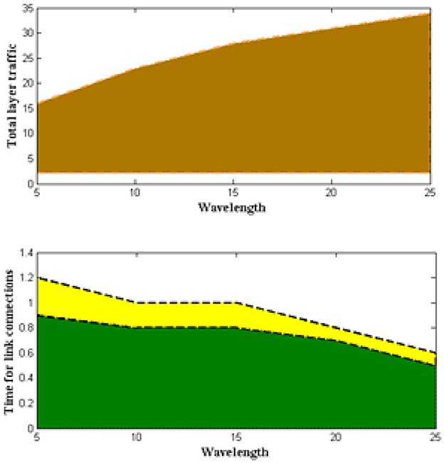
Figure 4. Reflection index with primary and secondary focus.
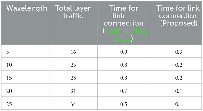
Table 4. Maximum time for connection.
4.4. Scenario 4
In all accessible places, real-time connection setups allow for the evaluation of fiber optic insulation effectiveness. In order for all linked panels to receive the proper power when a fiber optic connection is made to a specific energy source, no changes must be made after the connection. If the amount of generated power increases, the storage unit must take the appropriate action without experiencing any power drain issues. As a result, more co-processing fibers can be connected if necessary to provide modified efficiency. Additionally, it is necessary to test the input power of the optical transmission system and to use a reverse selection approach to increase the ratio of detection. The reverse selection mechanism's technique involves determining the appropriate installation angle for both index patterns in order to optimize modified efficiency, as shown in Figure 5. Only optical data moving in forward paths is used to measure the modified efficiency in the proposed method.

Figure 5. Efficiency of panel areas.
From Figure 5 and Table 5, it can be seen that the energy of forward paths and installation angles is accurately preserved without changing, but once a renewable energy source loses some of its own energy, the accuracy of detection decreases and must once again be extended to its maximum point. In order to measure the modified efficiency, the power of the optical path and coupling units are configured only at the maximum point. As a result of adding up all input power, the total power is represented as 1.33, 2.45, 3.96, 5.78, and 7.02 kilowatts, with each of the five accessible panel sections being 10, 15, 20, 25, and 30 accordingly.
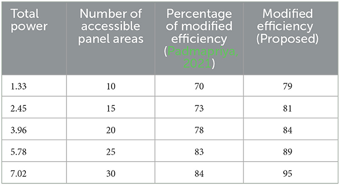
Table 5. Effectiveness with power considerations.
As a result, modified efficiency is shown in all accessible locations, and the comparison state with the existing method is given (Padmapriya, 2021), showing that the suggested method outperforms the existing strategy. This is supported by a total power of 3.96 kilowatts and 20 different accessible panel areas, where the modified efficiency for current and projected techniques is 78 and 84 percentage points, respectively.
4.5. Scenario 5
The overall amount of errors present during the interconnection stage is monitored and reduced using the projected technique. Finding two distinct sample values, referred to as “true” and “false,” is critical for reducing system errors. When a system has more false values, processing errors are considerably more likely to occur. Therefore, modification factors are offered by disregarding all false samples in order to avoid such processing cases. Once the false samples are disregarded, the output side will define the data representation values for the true data and generate the data. In order to minimize the error representation state, input data will be adjusted to avoid all false samples in optical networks. As a result, the difference between the generated and output data will be seen, and it will then be divided by the quantity of input data that is simulated and shown in Figure 6.
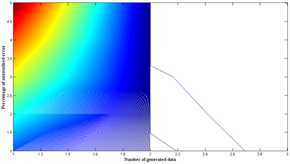
Figure 6. Comparison of normalized errors.
From Figure 6 and Table 6, it is reasonable to assume that the suggested method will result in fewer normalized errors when compared to the current methods. In order to simulate the normalized error function, the number of generated data is increased from 1,000 to 5,000, and the percentage of normalized errors is noted for each generated data set. Reducing the number of errors in the system and providing appropriate monitoring values are always necessary for better efficiency. To withstand the variable subsurface conditions, the percentage of normalized errors must also be kept below 1%. However, some system representations will change the undercoat parameters even after the errors are reduced. As a result, required map functions are established after modifying the undercoat parameters, and only input representations with low error levels are permitted to communicate. Renewable sources must be regularized with respect to specified input parameters if fiber optic systems exhibit higher error values.
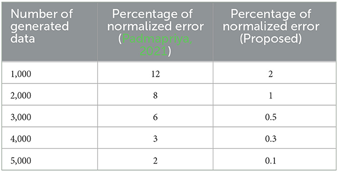
Table 6. Comparison of normalized errors.
4.6. Performance metrics
In this section, the performance characteristics of fiber optic networks are discussed as an extended version of experimental outcomes. The primary focus of performance evaluation is that apart from designed system model there is some robustness that exists with respect to defined true and false samples that are present with fiber optic restraints which needs to be reduced. Hence the evaluation metrics is carried out with respect to inconsistent robustness of the system which is assessed as follows.
4.6.1. Robustness characteristics
The initial measurement for robustness is carried out with false data set values where entire data is independent of fiber optic communication standard. Since false sample set is considered training and testing error conditions are present thus resulting in unstable traffic conditions. As a result of high traffic conditions in underwater networks the fiber optic communication becomes unstable thus increasing the loss periods even after integrating with GAN. Therefore to reduce the loss conditions only true sample set is considered after certain iterations with reduced errors at both training and testing phases where the reduced loss function outcomes are plotted in Figure 7.
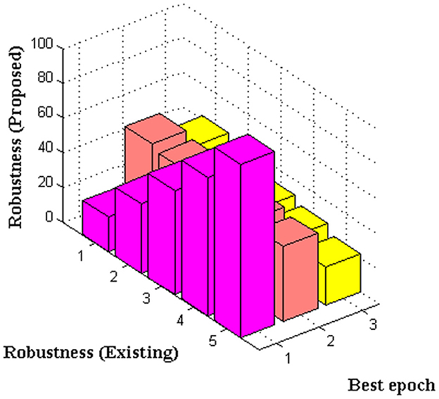
Figure 7. Robustness performance.
In Figure 7 the comparison case study indicates that robustness with respect to sample values are minimized for proposed system as compared to existing approach [4]. To prove such operating conditions best epoch is considered in step variations of 20 that extend till 100. Even it is possible to extend the epoch period but within the defined phase itself the training and testing errors of fiber optic transmission links are reduced. Therefore from the comparative display the loss function initially resides at 53 and 42 for existing and proposed methods. But once the iteration values are increased then robustness is reduced for both approaches with same data set representations but as compared to existing approach there is a high reduction with loss values for proposed method as it exist in 22 percentages for increasing epoch conditions.
5. Conclusion
The proposed method's outcomes are totally dependent on the utilization of fiber optics, which are coupled with a single renewable energy source and adequately covered to insulate them. The system's stability needs to be regularly evaluated every time a new fiber optic communication design model is released. In order to limit the amount of external disturbance in subsurface locations, mathematical approaches are used. The planned model will extend the support with a high-visibility pattern even if the suggested method is used to cover a huge area that is over one hundred meters long, so long as an adequate power supply is available for the externally coated panels. Additionally, GAN will lessen all faults that are present in fiber optic networks since external noise will be intermittent at the input side. In order to improve the efficiency of the suggested method and the safety of the specified technique, a coupler is also attached to external panels. Only real-time trials are employed to test the suggested technique after numerous assessments in the subsurface area. Step 1 involves checking the visibility pattern and creating the designed hardware connection to dangle at a shallow depth inside the subsurface region. Once the visibility pattern has been optimized and the reflection index for transmitted optical signals has been assessed and minimized, the adjusted efficiency is maximized. The intensification rate, link connection time, reflection index, processing time for transmission links, and error rates are other factors that are considered during the test phase. In comparison to the present method, the suggested method with GAN delivers the best optimized values in each of the aforementioned circumstances. The recommended strategy can be enhanced in the future to add data handling capabilities for various categories of renewable energy sources, resulting in a straightforward method of communication in subterranean areas.
5.1. Policy implications
The proposed method on fiber optic communications can be applied in all underwater testing industries to improve the following.
• To reduce significant threat that is observed at sea bed movement with radioactive dispersions.
• To minimize external noise factors that is present at a certain distance below the operating sea conditions.
Data availability statement
The original contributions presented in the study are included in the article/Supplementary material, further inquiries can be directed to the corresponding author.
Author contributions
TH and HM: conceptualization and writing-original draft. HM: formal analysis. HA: validation. GS: investigation. SS and HM: methodology. JL: writing-review and editing and funding acquisition. All authors contributed to the article and approved the submitted version.
Conflict of interest
The authors declare that the research was conducted in the absence of any commercial or financial relationships that could be construed as a potential conflict of interest.
Publisher's note
All claims expressed in this article are solely those of the authors and do not necessarily represent those of their affiliated organizations, or those of the publisher, the editors and the reviewers. Any product that may be evaluated in this article, or claim that may be made by its manufacturer, is not guaranteed or endorsed by the publisher.
Supplementary material
The Supplementary Material for this article can be found online at: https://www.frontiersin.org/articles/10.3389/fevo.2023.1132678/full#supplementary-material
References
Aslian, A., Honarvar Shakibaei Asli, B., Tan, C. J., Adikan, F. R. M., and Toloei, A. (2016). Design and analysis of an optical coupler for concentrated solar light using optical fibers in residential buildings. Int. J. Photoenergy. 2016, 3176052. doi: 10.1155/2016/3176052
Balamurugan, V., Karthikeyan, R., Sundaravadivazhagan, B., and Cyriac, R. (2022). Enhanced Elman spike neural network based fractional order discrete Tchebyshev encryption fostered big data analytical method for enhancing cloud data security. Wirel. Netw. 29, 523–537. doi: 10.1007/s11276-022-03142-2
Jin, L., Tan, F., and Jiang, S. (2020). Generative adversarial network technologies and applications in computer vision. Comput. Intell. Neurosci. 2020, 1459107. doi: 10.1155/2020/1459107
Karthikeyan, R., Balamurugan, V., Cyriac, R., and Sundaravadivazhagan, B. (2022). COSCO2: AI-augmented evolutionary algorithm-based workload prediction framework for sustainable cloud data centers. Trans. Emerging Telecomm. Tech. 34, e4652. doi: 10.1002/ett.4652
Kribus, A., Zik, O., and Karni, J. (2000). Optical fibers and solar power generation. Sol. Energy 68, 405–416. doi: 10.1016/S0038-092X(00)00009-8
Lin, G. R., and Lai, Y. C. (2015). Optical communications. Top. Appl. Phys. 129, 101–105. doi: 10.1063/5.0042337
Mata, J., de Miguel, I., Duran, R. J., Merayo, N., Singh, S. K., Jukan, A., et al. (2018). Artificial intelligence (AI) methods in optical networks: A comprehensive survey. Opt. Switch. Netw. 28, 43–57. doi: 10.1016/j.osn.2017.12.006
Nengroo, S. H., Jin, H., and Lee, S. (2022). Management of distributed renewable energy resources with the help of a wireless sensor network. Appl. Sci. 12, 6908. doi: 10.3390/app12146908
Nevin, J. W., Nallaperuma, S., Shevchenko, N. A., Li, X., Faruk, M. S., Savory, S. J., et al. (2021). Machine learning for optical fiber communication systems: An introduction and overview. APL Photonics 6, 121101. doi: 10.1063/5.0070838
Obukhov, S. G., Plotnikov, I. A., and Masolov, V. G. (2018). “Mathematical model of solar radiation based on climatological data from NASA SSE,” in IOP Conference Series: Materials Science and Engineering (IOP Publishing) p. 012021. doi: 10.1088/1757-899X/363/1/012021
Onyema, E. M., Kumar, M. A., Balasubaramanian, S., Bharany, S., Rehman, A. U., Eldin, E. T., et al. (2022). A security policy protocol for detection and prevention of internet control message protocol attacks in software defined networks. Sustainability 14, 11950. doi: 10.3390/su141911950
Padmapriya, T. (2021). Designing on Optical Wireless Communication for 5G Mobile Applications. Turkish J. Comput. Math. Educ. 12, 1472–1482. doi: 10.17762/turcomat.v12i3.945
Rosa, L. G., De Almeida, G., Pereira, J. C. G., Martínez-Hernández, A., and González-Aguilar, J. (2022). A method for determination of the transmission efficiency of a silica optical fiber cable using a solar power tower. Materials (Basel). 15, 1–15. doi: 10.3390/ma15041511
Sánchez, M. G., Macia, Y. M., Gil, A. F., Castro, C., González, S. M. N., and Yanes, J. P. (2020). A mathematical model for the optimization of renewable energy systems. Mathematics 9, 1–16. doi: 10.3390/math9010039
Schöndienst, T., and Vokkarane, V. M. (2014). Renewable energy-Aware grooming in optical networks. Photonic Netw. Commun. 28, 71–81. doi: 10.1007/s11107-014-0436-4
Schulze, H. (2018). FEM simulations for the wireless optical indoor communication channel. IET Optoelectron. 12, 94–105. doi: 10.1049/iet-opt.2017.0089
Sharma, K., and Sehgal, V. K. (2020). Energy-efficient and sustainable communication in optical networks on chip. Sustain. Comput. Inform. Syst. 28, 100426. doi: 10.1016/j.suscom.2020.100426
Teng, Y., Wang, P., Zhou, Y., and Wei, Y. (2022). Potential applications of distributed optical fiber sensor in hydrate-induced sedimentary deformation research. Energy Sci. Eng. 10, 4–12. doi: 10.1002/ese3.1016
Tzarouchis, D. C., Mencagli, M. J., Edwards, B., and Engheta, N. (2022). Mathematical operations and equation solving with reconfigurable metadevices. Light Sci. Appl. 11, 1–13. doi: 10.1038/s41377-022-00950-1
Venketeswaran, A., Lalam, N., Wuenschell, J., Ohodnicki, P. R., Badar, M., Chen, K. P., et al. (2022). Recent advances in machine learning for fiber optic sensor applications. Adv. Intell. Syst. 4, 2100067. doi: 10.1002/aisy.202100067
Keywords: energy sources, fiber optics, artificial intelligence (AI), visibility, reflection index
Citation: Hasanin T, Manoharan H, Alterazi HA, Srivastava G, Selvarajan S and Lin JC-W (2023) Mathematical approach of fiber optics for renewable energy sources using general adversarial networks. Front. Ecol. Evol. 11:1132678. doi: 10.3389/fevo.2023.1132678
Received: 27 December 2022; Accepted: 31 January 2023;
Published: 23 February 2023.
Edited by:
Praveen Kumar Donta, Vienna University of Technology, AustriaReviewed by:
Sundaravadivazhagan Balasubaramainan, University of Technology and Applied Sciences, OmanS. Devakirubakaran, QIS College of Engineering and Technology, India
D. Yuvaraj, Cihan University, Iraq
Copyright © 2023 Hasanin, Manoharan, Alterazi, Srivastava, Selvarajan and Lin. This is an open-access article distributed under the terms of the Creative Commons Attribution License (CC BY). The use, distribution or reproduction in other forums is permitted, provided the original author(s) and the copyright owner(s) are credited and that the original publication in this journal is cited, in accordance with accepted academic practice. No use, distribution or reproduction is permitted which does not comply with these terms.
*Correspondence: Jerry Chun-Wei Lin,  jerrylin@ieee.org; Hariprasath Manoharan, hari13prasath@gmail.com