Experimental study for thermal methane cracking reaction to generate very pure hydrogen in small or medium scales by using regenerative reactor
 Mahdi Yousefi
 Scott Donne
- PRC for Frontier Energy Technologies and Utilization, University of Newcastle, Callaghan, NSW, Australia
Non-catalytic thermal methane cracking (TMC) is an alternative for hydrogen manufacturing and traditional commercial processes in small-scale hydrogen generation. Supplying the high-level temperatures (850–1800°C) inside the reactors and reactor blockages are two fundamental challenges for developing this technology on an industrial scale (Mahdi Yousefi and Donne, 2021). A regenerative reactor could be a part of a solution to overcome these obstacles. This study conducted an experimental study in a regenerative reactor environment between 850 and 1,170°C to collect the conversion data and investigate the reactor efficiency for TMC processes. The results revealed that the storage medium was a bed for carbon deposition and successfully supplied the reaction’s heat, with more than 99.7% hydrogen yield (at more than 1,150°C). Results also indicated that the reaction rate at the beginning of the reactor is much higher, and the temperature dependence in the early stages of the reaction is considerably higher. However, after reaching a particular concentration of Hydrogen at each temperature, the influence of temperature on the reaction rate decreases and is almost constant. The type of produced carbon in the storage medium and its auto-catalytic effect on the reactions were also investigated. Results showed that carbon black had been mostly formed but in different sizes from 100 to 2000 nm. Increasing the reactor temperature decreased the size of the generated carbon. Pre-produced carbon in the reactor did not affect the production rate and is almost negligible at more than 850°C.
Introduction
Hydrogen is a vital chemical commodity and potentially plays a crucial role in the future’s clean, secure and affordable energy scenarios (Mahdi Yousefi and Donne, 2021). Hydrogen fuel consumption in industry, especially on small and medium scales, and even residential consumption, will be one of the basic needs of the future. In this way, technology and engineering knowledge of hydrogen production can play a key role in the future hydrogen consumption market, especially on small scales. Generally, hydrogen production can be divided into two categories. The first category concerns hydrogen production from fossil fuels such as oil and gas. Currently, the worldwide production of Hydrogen is primarily from fossil fuel sources such as natural gas, coal and oil. Steam reforming of methane, coal gasification and partial oxidation are the main processes for hydrogen production on an industrial scale by using fossil fuel sources (Bossel et al., 2004; Takenaka et al., 2004; Winter 2007).
The second category of conventional hydrogen production methods involves hydrogen production using non-fossil sources such as water electrolysis, through biochemicals and photo-electrochemical, which account for only about 4% of total global hydrogen production (Lane and Spath, 2001). The main reason for the small contribution of these technologies to hydrogen production is the high cost of hydrogen production compared to production processes using fossil fuels. The thermodynamic energy required for hydrogen production by the electrolysis process is more than 33 kWh/kg, which is too higher than steam reforming with carbon capture and higher than methane pyrolysis. Even if the electricity comes from renewable or nuclear processes, it is not currently economically feasible (Abánades et al., 2013; Ashik et al., 2015). There are still many obstacles to improving hydrogen usage on small and medium-sized scales. Currently, Hydrogen produced in the industry is mostly considered a chemical product and not a fuel (Mahdi Yousefi and Donne, 2021). The commercial sale of Hydrogen is less than 10% of the world’s hydrogen production, estimated at 20 million tons per year. It means that 90% of the Hydrogen produced is consumed at the production site. Today, only a small fraction of the Hydrogen produced is used as an energy carrier (Nazir et al., 2020). Different methods of producing Hydrogen from different energy sources have unique needs and produce or distribute unique by-products. Optimizing and producing Hydrogen on a small and medium scale in commercial hydrogen production methods requires further research and development of prototypes (Mahdi Yousefi and Donne, 2021). Advanced methods for Hydrogen purifying and separation of pollutants are needed to reduce the prices of produced Hydrogen and increase efficiency. More appropriate methods are needed for both stationary and dispersed hydrogen production, and efforts should be made on new processes in developing advanced techniques. In the reactors of current industrial processes, such as methane reforming, Hydrogen is produced in a mixture with other chemical compounds such as carbon dioxide, carbon monoxide, water, and other hydrocarbon compounds. Therefore, using the separation and purification units in these processes is necessary. This operation is performed by equipment such as distillation and adsorption towers or membrane technology (Eckerle, 2001). The equipment’s sizes and operating pressure of these unit operations are relatively large, making it unfeasible to use in small hydrogen production units.
In the near future, there will be a need to produce Hydrogen in different places, such as residential, industrial, energy parks, and service stations in different communities.
The low density of hydrogen gas makes it difficult to use Hydrogen as an energy carrier. It means that compared to liquid fuels such as gasoline or methanol, it has a low energy content per unit volume (about 1.5 kJ per kilogram). Liquid Hydrogen has the highest energy density of all fuels. However, it must be stored at very low temperatures (-253°C) and high pressures, making it difficult to store and transport.
Hydrogen does not exist purely in nature and must be obtained from water or fuels such as coal, natural gas, oil, methanol and ethanol, which have Hydrogen in their molecular structure. The fuel converters to produce high purity hydrogen on small or medium scales is a necessity that needs special attention. The function of the fuel converter is to convert the required Hydrogen using the fuels that are available and easy to transport. Fuel converters must be able to do this with the least pollution and the highest efficiency. In simple terms, fuel converters are to convert a hydrogen-rich fuel into Hydrogen and by-products (environmentally friendly or capturable).
Natural gas is one of the most widely available fossil fuels in almost all parts of the world. Natural gas is available through transmission pipes in many cities, industrial areas and service stations and can be easily used in different places.
Conventional hydrogen production processes need purification and separation unit operations, such as methane steam reforming, coal gasification, and partial oxidation. Also, hydrogen production by electricity is not reasonable, while one of the most important applications is generating electricity in fuel cells. Therefore, most of the existing technologies do not possess the ability to be used in a small or medium-scale production plant, and the hydrogen economy is engaged with cost obstacles such as high compression, liquefaction, transportation and storage costs.
Methane thermal cracking (MTC) is an alternative for high purity hydrogen production on small and medium scales. In this process, methane is converted to Hydrogen in the gas phase and carbon in the solid phase at high temperatures without oxygen. This process can produce very pure Hydrogen (99.99%), which almost does not require additional processing to separate and purify hydrogen gas (Abánades et al., 2013). No need for purification and separation units of the MTC process creates this potential to convert natural gas to pure Hydrogen on a small or medium-scale converter.
Using catalysts in the MTC process can significantly reduce the converter’s operating temperature (below 800°C). Various scientific research has been conducted on catalytic thermal methane cracking with different catalysts types, and their results have been the subject of many scientific journals. Despite some promising results, very quick catalyst deactivation is the main obstacle to the industrial development of this process (Ashik et al., 2015; Mahdi Yousefi and Donne, 2021). Higher operating temperatures (above 850°C) can also lead to a high conversion of methane to Hydrogen and carbon in a non-catalytic way. However, it is yet to develop on an industrial or commercial scale. The main problems of this process are the production of a high amount of carbon in the reactor, which leads to the reactor blockage and suppling the reaction heat at high temperatures (more than 850 C) (Muradov, 2001).
Various scientific research has been conducted to develop this technology (non-catalytic MTC) in recent years. It has been the subject of many scientific articles and research that shows the promise to overcome the obstacles to developing this technology (Mahdi Yousefi and Donne, 2021).
A tubular reactor has been employed in some research to perform the TMC reaction in the lab scales (Abánades et al., 2011; Mahdi Yousefi and Donne, 2021). However, it could not be a simple multiplication of tubes on an industrial scale to attain a reasonable amount of hydrogen production. Additionally, the reactor blockage produced carbon was another issue in developing this type of reactor. In this way, melted metal reactors could be a good choice, but the methane conversion rate is not high enough to prevent the need for a purification unit (Gulevich et al., 2008; Paxman et al., 2014). It was also noted that increasing the temperature for a complete conversion led to other problems like corrosion, carbon separation and melted metal feeding (Shimotake and Hesson, 1965; Xu et al., 2002; Geißler et al., 2015).
As a result, reactor blockages and heat supply for the endothermic reaction are two fundamental obstacles to developing thermal methane cracking on small and medium scales (Mahdi Yousefi and Donne, 2021). Employing regenerative reactors could be a solution to overcome those obstacles. The regenerative reactor concept is based on the indirect coupling of endothermic reaction energy with an external energy source stream using the storage medium. Typically, a regenerative reactor has two cycles. In the first cycle, heat will be stored in the stored medium, such as ceramic packing, and then in the second cycle, the heat will be passed to the endothermic reaction stream (Zarrinehkafsh and Sadrameli, 2004; Kilkovsky and Jegla, 2016). The storage medium delivers a bed for carbon deposition and can play a heat source role in storing and releasing the heat to the gas stream. Furthermore, it can increase intermolecular collisions and increase turbulently and/or gas flow mixing, which can directly affect the reaction rate in a regenerative reactor environment.
The Formation of a carbon layer on the storage medium could catalyze methane decomposition reaction to Hydrogen and carbon. Different types of carbon can lead to a diverse catalytic effect on the methane decomposition reaction (Dean, 1990; Muradov, 2001; Ashik et al., 2015). The type of carbon formed and its activity also depend on the reaction conditions such as temperature or pressure. For example, Muradov et al. (Muradov, 2001)examined the influence of numerous carbon-based catalysts. It was found that disordered types such as activated carbon (AC), and the amorphous and carbon black (CB) forms illustrate higher catalytic activity than ordered ones such as graphite and diamond.
Hence, a ceramic-packed bed reactor has investigated TMC reaction kinetics in a regenerative reactor environment. Additionally, this paper investigates the possible effect of carbon formation inside the reactor.
Regenerative reactor concepts
As shown in Figure 1, the regenerator reactor is a type of heat exchanger where heat from the hot fluid is intermittently stored in a thermal storage medium like ceramic mass before it is transferred to the cold stream. This type of reactor is very simple, and it can be used in home units and on small or medium scales. If a high temperature is provided, it can produce pure Hydrogen without needing ancillary units.
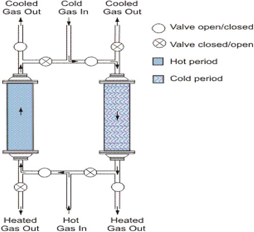
FIGURE 1. Schematic of regenerative heat exchangers and its arrangement.
The hot stream is brought into contact with the heat storage medium, and the gas is displaced with the cold stream, which absorbs the heat. Usually, the application will use this process cyclically or repetitively. (Takenaka et al., 2004).
Also, it is possible to use the regenerative heat exchangers to heat the raw materials and cool down the products in each cycle. As shown in Figure 2, a ceramic bed has been considered before and after the hot zone. In generating cycle, methane is heated to near reaction temperature, and Hydrogen will be cooled after that exit from the reactor in each cycle.
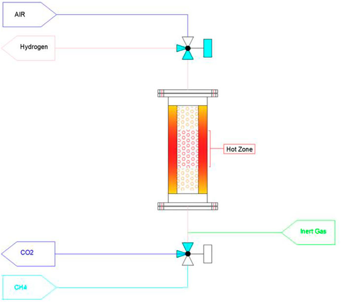
FIGURE 2. Regenerative reactor arrangments for heating the methane and cooling down the Hydrogen.
In the integrated model, the gas temperature in the outlet of reactors is reduced, and it is preferable in terms of material selection for pipes and valves.
It is possible to burn out a part of the deposited carbon inside the reactor for heating the storage medium by injecting the air. The burning heat in the regeneration step is more than 3.5 times higher than in the TMC reaction. It is possible to save extra energy by producing steam or hot water using a waste boiler or other heat exchanger.
Experiments set-up description
A packed bed reactor was employed to investigate methane decarbonization in a regenerative reactor environment. The reactor was made from Inconel alloy (80 cm length and 5 cm inner diameter) filled with inert ceramic balls (8 mm diameter). The reactor was situated in a vertical tube furnace (Figure 3) so that the hot zone length in the middle of the reactor was 60 cm, and about 10 cm length at the beginning and end of the reactor were considered to preheat/cool out the inlet and outlet gases. Three gas mass flow controllers adjusted the flow rates for dilution/purging gas (nitrogen), methane or air (Figures 4, 5). The air was used only to clean up the inside of the reactor and burn the deposited carbon.
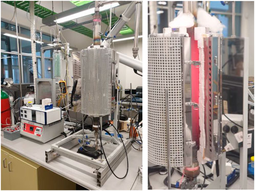
FIGURE 3. The regenerative reactor and split vertical furnace photos.
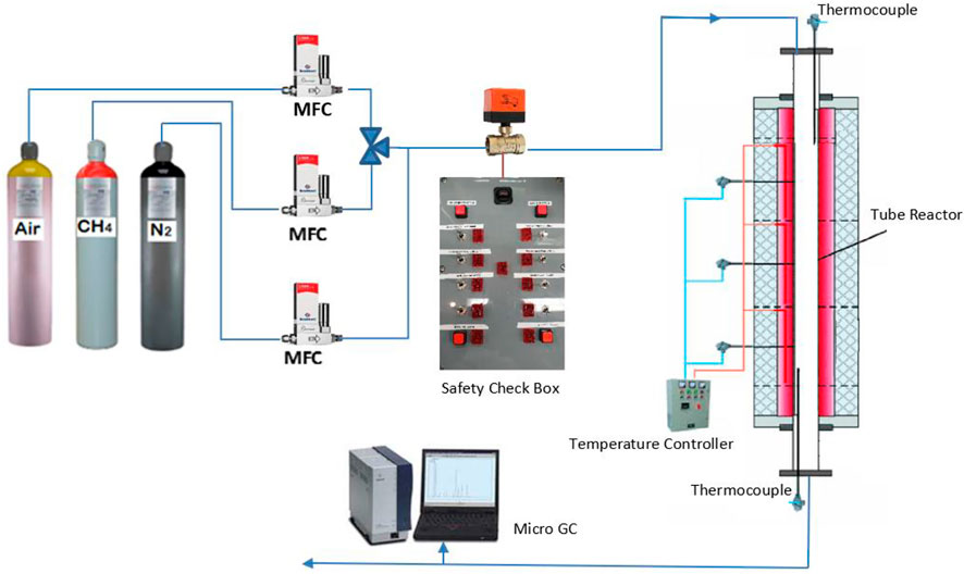
FIGURE 4. Schematic of the set-up arrangement.
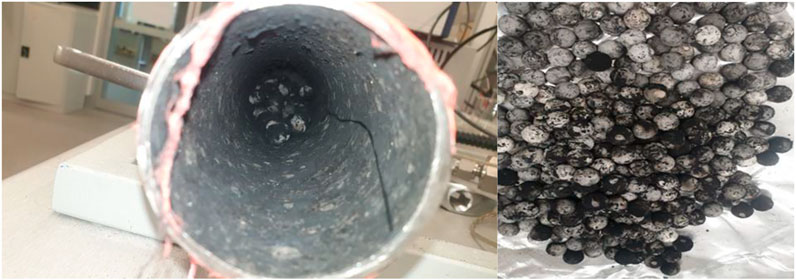
FIGURE 5. Photograph inside the reactor after 10 min of injecting methane at 1,000°C.
The experiment was carried out for the different flow rates and temperatures. Further tests were conducted to evaluate the repeatability of the results. A micro-GC was used to analyze the outlet gas materials. To eliminate any possible catalytic effect of the reactor body on the reaction, the methane cracking is conducted inside the reactor for a long enough time at 1,000°C (more than 20 h). Then, a thin layer of carbon will cover the inner face of the tube reactor. Based on the results, there is an assurance that any possible catalytic effect of the reactor body will be negligible due to a permanent deactivation effect. After that, the experiment was conducted. The carbon layer is formed during the first methane cracking to de-active any catalytic effect of the reactor body.
The furnace temperature was fixed at a specific temperature, and after the pipe and ceramic balls reached the set-point, methane was injected into the reactor.
Nitrogen gas is gradually injected into the reactor during the preheating to uniform the temperature inside the reactor and ceramics packings. When the thermocouples inside the reactor remain constant at the desired temperature and the micro GC, which shows the amount of oxygen in the exiting gas from the reactor, is zero, methane will be injected into the reactor at diffident temperatures and flowrates.
For obtaining the actual gas residence time inside the reactor, assume that each mole of methane in the reactor will be converted to 2 mol of Hydrogen after decomposition. The amount of residence time in the reactor at each temperature, pressure and conversion rate is calculated based on Eqs. 1,2:
Results and discussion
The hydrogen yield
Figure 6 shows the amount of Hydrogen at different temperatures and flow rates at the reactor outlet.
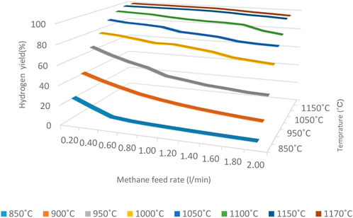
FIGURE 6. The hydrogen yield at different temperatures and flow rates.
The hydrogen yield has increased by increasing the reactor temperature. It is more evident when the temperature rises from 850 to 1,000 C and leads to a significant increase in hydrogen yield; for example, in the lowest methane flow rate, with increasing the reactor temperature from 850 to 900 C, the produced Hydrogen has nearly doubled.
Increasing the methane feed rate to the reactor will decrease residence time, which leads to a reduction in methane cracking. The residence time plays a more prominent role at lower temperatures (lower than 1,000°C) to provide the required energy of thermal methane cracking reaction for an instant, at a constant temperature of 850°C when the methane feed rate increases from 0.2 to 2 L per second, the percentage of Hydrogen in the reactor output decreases from 29.2% to 3.4% while at 900°C, with increasing flow rate from 0.2 to 2 L per second, the hydrogen yield at the reactor outlet decreases from 47.56% to 17.5%, and by increasing the temperature to 950°C, Hydrogen at the reactor outlet decreases from 67.4% to 34.9%. As can be seen, with increasing the temperature, the intensity of the hydrogen reduction has been reduced when the methane feed rate increases.
At 1,000°C, The slope of the hydrogen yield changing is reduced, and hydrogen percentage decreases from 79.5% to 60% at temperatures above 1,000 C, and the slope tends to zero. It indicates that the reaction took place at the beginning of the reactor and the residence time is not a very effective parameter in higher temperatures. Increasing the conversion rate at higher temperatures (more than1050°C) would cause a significant reduction in the required size of the reactor.
The results show that the conversion of methane to Hydrogen at temperatures above 1,150°C and flow rate less than 1.2 ml/m is almost complete, indicating that the reactor temperature must be more than 1,150°C for complete methane conversion to Hydrogen.
The measured amount of methane at the end of the reactor reveals that intermediate components or by-products are negligible. It was mostly due to the high enough reactor volume and temperature to prevent by-product formation.
Figure 7 shows the amount of Hydrogen relative to the residence time at each temperature.
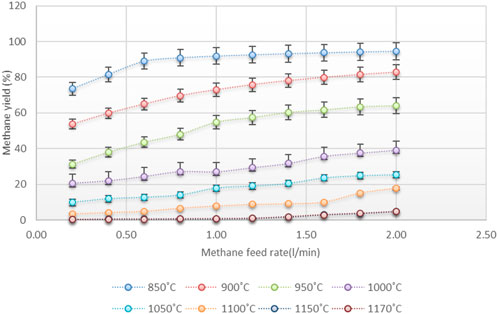
FIGURE 7. The hydrogen yield relative to the retention time at each temperature and atmospheric pressure.
Most researchers considered first-order reactions based on a review of related scientific publications (Ashik et al., 2015).
By assuming that the reaction is a first-order once:
By plotting ln [
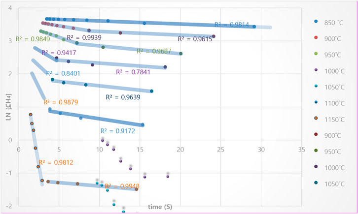
FIGURE 8. The plot of Ln [CH4t] vs. time, at 850 to 1,150°C, based on first-order reaction of methane cracking at the isothermal condition and in a regenerative reactor environment.
By increasing the temperature to 900°C and 1,050°C, there is a more deviation from the linear model. However, the slope of the diagram (as shown in diagram 8) again becomes linear with a high approximation by separating the last points. However, this issue is repeated at higher temperatures up to 1,150°C, and the graph’s slope changes completely. So, at the 900 to 1,150°C temperature range, the reaction rate changes from one point onwards and indicates a change in the reactivity mechanism. The hypothesis may justify this phenomenon: at high range temperatures (higher than 900 C), the reaction occurs when methane temperature rises at the reactor’s beginning (non-isothermally reaction). In this temperature range, the reaction at the beginning of the reactor is much higher, and its temperature dependence is much more.
The residence time (
Here
The type of produced carbon in the reactor
The temperature profile inside the reactor can make different types of carbon structures. Due to the nature of a regenerative reactor in which the storage medium’s temperature fluctuates in a certain range, this phenomenon may create different types of carbon that can have different catalytic properties for the methane decomposition reaction. So, it is tried to specify the type of produced carbon in three different temperature ranges of 850, 1,000 and 1,150°C inside the reactor. For this purpose, after fixing the reactor temperature at 850, 1,000 and 1,150°C, methane was injected into the reactor with a flow rate of 1 L per minute for 2 h. Then samples of the produced carbon were collected and analyzed.
Determining the exact morphology of the carbon produced in the reactor was not one of the main goals of this research. Rather, only the general determination of the type of carbon produced has been considered in order to conclude the possibility of any possible auto-catalytic effect. Carbon is generally produced in graphite, carbon black, carbon nanotubes or carbon nanofibers forms in these reactors. Typically, each carbon type has a recognizable shape on the micro to nanometer scales that can be easily recognized. The characteristics of the carbon aggregations were compared with the microstructure and morphology of carbon black provided by Medalia et al. (Medalia and Heckman, 1969) and Lahaye et al. (Lahaye and Ehrburger-Dolle, 1994) and some other references. The analysis of the characteristics of the deposited carbon shows that in all three conditions, mostly carbon black has been formed but in different sizes. Four samples at each temperature of carbon formation on the ceramics are collected randomly. The ceramics were selected at a distance of at least 15 cm from the reactor inlet to ensure that their formation temperature corresponded to the reactor’s temperature. The collected samples are packed in separate containers for each ceramic and sent to the lab to conduct SEM imaging. Figures 9–11 demonstrate the Scanning Electron Microscope (SEM) analyses of the amorphous carbon black sample produced at 850°C on the storage medium. It shows that the length of generated carbon is 100–2000 nm range.
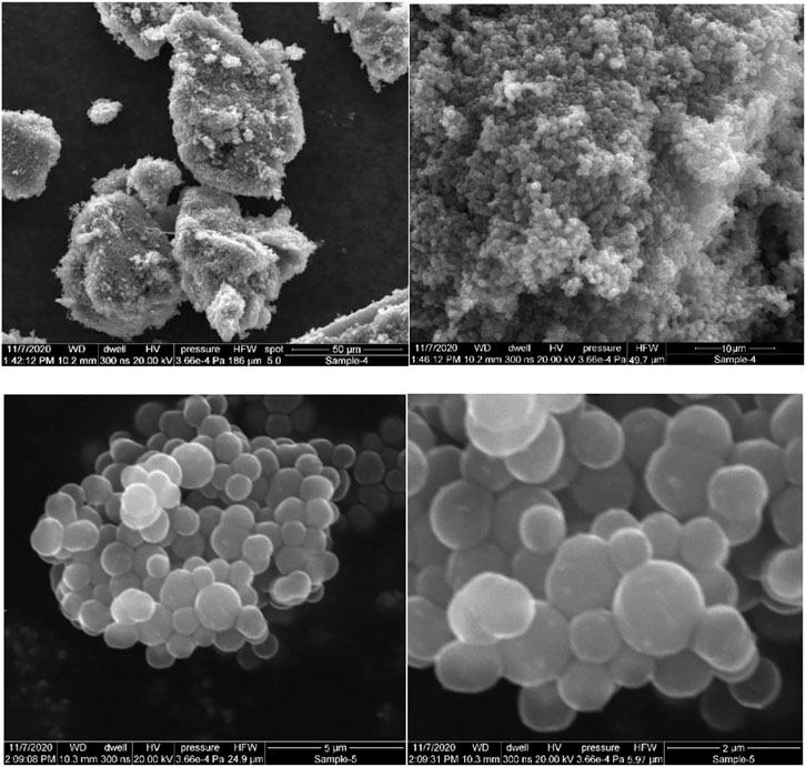
FIGURE 9. The SEM photos of the amorphous carbon black sample produced at the 850 ˚C and atmospheric pressure on the storage medium. It shows that the length of generated carbon is 0.5–2 µm range.
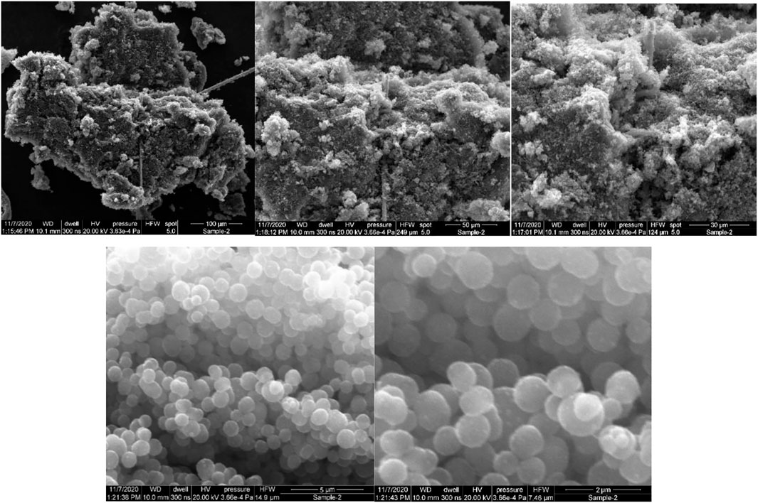
FIGURE 10. The SEM photos of the amorphous carbon black sample produced at the 1,000°C and atmospheric pressure on the storage medium. It shows that the length of generated carbon is 0.5–1 µm range.
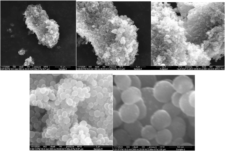
FIGURE 11. The SEM photos of the amorphous carbon black sample produced at the 850˚C and atmospheric pressure on the storage medium. It shows that the length of generated carbon is 100–500 nm range.
Figures 9–11 show that the type of produced carbon did not change, and carbon black was produced in almost all three temperature ranges by increasing temperature. By increasing the temperature, only the size of the carbon black is decreased, leading to a greater contact surface area. Carbon black with a higher contact surface area could increase the reaction rate (Trimm, 1977).
This hypothesis can explain why carbon size reduction by raising the reactor temperature increases the reaction rate significantly while the residence time has been decreased, so the rate of nucleation against the growth will be increased. In other words, the reaction rate limits the opportunity for the migration of new produced carbon to grow previous carbons particles.
The surface chemistry and pore size distribution would be important parameters for the initial rate conversion of methane and the catalyst’s long-term stability, respectively, in lower temperatures (less than 850 C°) (Ashok et al., 2007; Suelves et al., 2009; Figueiredo et al., 2010; Wei et al., 2011).
Investigating the possible catalytic effect of generated carbon on the reaction
A certain amount of carbon is first deposited on the ceramic balls to investigate the possible catalytic effect of carbon formed inside the reactor. Repeat all previous tests shown in Figure 6, and the result is compared. For this purpose, after heating the reactor at 850, 1,000 and 1,150°C and before starting the experiments, methane gas was injected into the reactor for 10 min and one lit/min flow rate so that a layer of carbon deposited on the internal reactor surface ceramic balls.
Diagrams 12 to 14 show the amount of Hydrogen leaving the reactor at 850°C and different flow rates.
Figures 12–14 show that the injection of methane in the presence of pre-produced carbon in the reactor does not affect methane conversion improvement. The maximum change was at 850°C, making less than a 4.5% increase in the conversion on the lowest methane flow rate. At temperatures of 1,000°C and 1,150°C, the increased conversion of methane to Hydrogen was almost negligible. This phenomenon may be explained by the fact that the reaction rate is a function of the active catalytic surface which decreases with reaction progress due to carbon deposition. Therefore, the catalytic effect is ignorable because the reaction rate strongly depends on the reaction temperature.
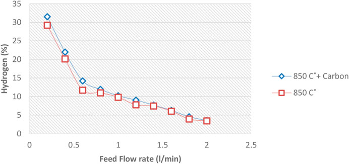
FIGURE 12. The amount of Hydrogen leaving the reactor at 850°C and 0–2 lit/min flowrates.
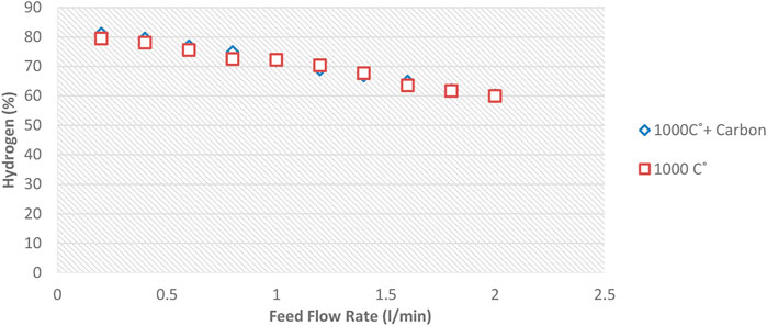
FIGURE 13. The amount of Hydrogen leaving the reactor at 1,000°C and 0–2 lit/min flowrates.
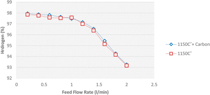
FIGURE 14. The amount of Hydrogen leaving the reactor at 1,150°C and 0–2 lit/min flow rates.
Therefore, it can be concluded that pre-produced carbon black, as one of the reactor products, has little effect on increasing the conversion rate. Different sizes of carbon black will not have much effect on conversion. Notably, the void fraction decreases over time in a regenerative reactor due to carbon deposition.
Conclusion
This experiment investigated the thermal methane cracking in a regenerative reactor environment at atmospheric pressure and 850–1,170 °C. Results showed that the reaction rate at the beginning of the reactor is much higher. Also, its temperature dependence is much more. However, after reaching a specific concentration of Hydrogen at each reactor temperature, the influence of temperature on the reaction rate decreases and is almost constant. At 850°C, the hydrogen yield decreases at an almost constant rate relative to the residence time along the reactor. However, at higher temperatures, the reaction rate in the early stages is much higher than in later. At temperatures above 1150C°, the reaction will almost be completed at the beginning of the reactor.
The characteristics of the deposited carbon showed that mostly carbon black had been formed (at 850–1,150 C). By increasing temperature, the size of the produced carbon was decreased from 100 nm (at 1,150 C) to 2,000 nm (at 850 C). Also, pre-produced carbon in the reactor will not have much effect on increasing the production rate and was almost negligible at temperatures more than 850°C.
Data availability statement
The original contributions presented in the study are included in the article/supplementary materials, further inquiries can be directed to the corresponding author.
Author contributions
MY: This research is a part of my PhD project conducted at the University of Newcastle, Australia. SD is my supervisor.
Acknowledgments
The authors acknowledge the financial support provided by the University of Newcastle, Australia, for the work presented in this paper.
Conflict of interest
The authors declare that the research was conducted in the absence of any commercial or financial relationships that could be construed as a potential conflict of interest.
Publisher’s note
All claims expressed in this article are solely those of the authors and do not necessarily represent those of their affiliated organizations, or those of the publisher, the editors and the reviewers. Any product that may be evaluated in this article, or claim that may be made by its manufacturer, is not guaranteed or endorsed by the publisher.
References
Abánades, A., Rubbia, C., and Salmieri, D. (2013). Thermal cracking of methane into Hydrogen for a CO2-free utilization of natural gas. Int. J. hydrogen energy 38 (20), 8491–8496. doi:10.1016/j.ijhydene.2012.08.138
Abánades, A., Ruiz, E., Ferruelo, E., Hernandez, F., Cabanillas, A., Martinez-Val, J., et al. (2011). Experimental analysis of direct thermal methane cracking. Int. J. hydrogen energy 36 (20), 12877–12886. doi:10.1016/j.ijhydene.2011.07.081
Ashik, U., Daud, W. W., and Abbas, H. F. (2015). Production of greenhouse gas free hydrogen by thermocatalytic decomposition of methane–a review. Renew. Sustain. Energy Rev. 44, 221–256. doi:10.1016/j.rser.2014.12.025
Ashok, J., Naveen Kumar, S., Subrahmanyam, M., and Venugopal, A. (2007). Production of COx free hydrogen by catalytic decomposition of methane over Ni/HY catalysts. Catal. Lett. 118 (1-2), 139–145. doi:10.1007/s10562-007-9170-1
Bossel, U., Eliasson, B., and Taylor, G. (2004). The future of the hydrogen economy: Bright or bleak? J. KONES 11 (1-2), 87–111.
Dean, A. M. (1990). Detailed kinetic modeling of autocatalysis in methane pyrolysis. J. Phys. Chem. 94 (4), 1432–1439. doi:10.1021/j100367a043
Eckerle, A. (2001). Abstracts of papers of the American chemical society. 16TH ST, NW, WASHINGTON, DC 20036 USA: AMER CHEMICAL SOC.Ullmann's Encyclopedia of Industrial Chemistry: From print to electronic
Figueiredo, J., Órfão, J., and Cunha, A. (2010). Hydrogen production via methane decomposition on Raney-type catalysts. Int. J. Hydrogen Energy 35 (18), 9795–9800. doi:10.1016/j.ijhydene.2009.12.071
Geißler, T., Plevan, M., Abanades, A., Heinzel, A., Mehravaran, K., Rathnam, R., et al. (2015). Experimental investigation and thermo-chemical modeling of methane pyrolysis in a liquid metal bubble column reactor with a packed bed. Int. J. Hydrogen Energy 40 (41), 14134–14146. doi:10.1016/j.ijhydene.2015.08.102
Gulevich, A., Martynov, P., Gulevsky, V., and Ulyanov, V. (2008). Technologies for hydrogen production based on direct contact of gaseous hydrocarbons and evaporated water with molten Pb or Pb–Bi. Energy Convers. Manag. 49 (7), 1946–1950. doi:10.1016/j.enconman.2007.12.028
Kilkovsky, B., and Jegla, Z. (2016). Preliminary design and analysis of regenerative heat exchanger. Pres2016: 19th international conference on process integration. Model. Optim. Energy Savings Pollut. Reduct. 52, 655–660. doi:10.3303/CET1652110
Lahaye, J., and Ehrburger-Dolle, F. (1994). Mechanisms of carbon black formation. Correl. Morphol. Aggregates, Carbon 32 (7), 1319–1324. doi:10.1016/0008-6223(94)90118-X
Lane, J., and Spath, P. (2001). Technoeconomic analysis of the thermocatalytic decomposition of natural gas. Golden, CO (US): National Renewable Energy Lab.
Lee, K. K., Han, G. Y., Yoon, K. J., and Lee, B. K. (2004). Thermocatalytic hydrogen production from the methane in a fluidized bed with activated carbon catalyst. Catal. Today 93, 81–86. doi:10.1016/j.cattod.2004.06.080
Mahdi Yousefi, S. D., and Donne, S. (2021). Technical challenges for developing thermal methane cracking in small or medium scales to produce pure hydrogen - a review. Int. J. Hydrogen Energy 47, 699–727. doi:10.1016/j.ijhydene.2021.10.100
Medalia, A., and Heckman, F. (1969). Morphology of aggregates—II. Size and shape factors of carbon black aggregates from electron microscopy. Carbon 7 (5), 567–582. doi:10.1016/0008-6223(69)90029-3
Muradov, N. (2001). Catalysis of methane decomposition over elemental carbon. Catal. Commun. 2 (3), 89–94. doi:10.1016/s1566-7367(01)00013-9
Nazir, H., Muthuswamy, N., Louis, C., Jose, S., Prakash, J., Buan, M. E., et al. (2020). Is the H2 economy realizable in the foreseeable future? Part III: H2 usage technologies, applications, and challenges and opportunities. Int. J. hydrogen energy 45 (53), 28217–28239. doi:10.1016/j.ijhydene.2020.07.256
Paxman, D., Trottier, S., Nikoo, M., Secanell, M., and Ordorica-Garcia, G. (2014). Initial experimental and theoretical investigation of solar molten media methane cracking for hydrogen production. Energy Procedia 49, 2027–2036. doi:10.1016/j.egypro.2014.03.215
Shimotake, H., and Hesson, J. (1965). Static and dynamic corrosion by tin, bismuth and bismuth-sodium alloy up to 1000 deg C. Trans. Amer. Nucl. Soc. 8, 3.
Suelves, I., Pinilla, J., Lazaro, M., Moliner, R., and Palacios, J. (2009). Effects of reaction conditions on hydrogen production and carbon nanofiber properties generated by methane decomposition in a fixed bed reactor using a NiCuAl catalyst. J. Power Sources 192 (1), 35–42. doi:10.1016/j.jpowsour.2008.11.096
Takenaka, S., Ishida, M., Serizawa, M., Tanabe, E., and Otsuka, K. (2004). Formation of carbon nanofibers and carbon nanotubes through methane decomposition over supported cobalt catalysts. J. Phys. Chem. B 108 (31), 11464–11472. doi:10.1021/jp048827t
Trimm, D. L. (1977). The formation and removal of coke from nickel catalyst. Catal. Rev. 16 (1), 155–189. doi:10.1080/03602457708079636
Trommer, D., Hirsch, D., and Steinfeld, A. (2004). Kinetic investigation of the thermal decomposition of CH4 by direct irradiation of a vortex-flow laden with carbon particles. Int. J. Hydrogen Energy 29 (6), 627–633. doi:10.1016/j.ijhydene.2003.07.001
Wei, L., Tan, Y. s., Han, Y. z., Zhao, J. t., Wu, J., and Zhang, D. (2011). Hydrogen production by methane cracking over different coal chars. Fuel 90 (11), 3473–3479. doi:10.1016/j.fuel.2011.06.053
Xu, L., Xie, S., Liu, S., Lin, L., Tian, Z., and Zhu, A. (2002). Combination of CH4 oxidative coupling reaction with C2H6 oxidative dehydrogenation by CO2 to C2H4. Fuel 81 (11-12), 1593–1597. doi:10.1016/s0016-2361(02)00074-1
Keywords: thermal methane cracking, hydrogen production, regenerative reactor, hydrogen, methane decarbonization
Citation: Yousefi M and Donne S (2022) Experimental study for thermal methane cracking reaction to generate very pure hydrogen in small or medium scales by using regenerative reactor. Front. Energy Res. 10:971383. doi: 10.3389/fenrg.2022.971383
Received: 17 June 2022; Accepted: 08 August 2022;
Published: 02 September 2022.
Edited by:
Zhenjiang You, Edith Cowan University, AustraliaReviewed by:
Feng Wang, Chongqing University, ChinaPeter P. Edwards, University of Oxford, United Kingdom
Copyright © 2022 Yousefi and Donne. This is an open-access article distributed under the terms of the Creative Commons Attribution License (CC BY). The use, distribution or reproduction in other forums is permitted, provided the original author(s) and the copyright owner(s) are credited and that the original publication in this journal is cited, in accordance with accepted academic practice. No use, distribution or reproduction is permitted which does not comply with these terms.
*Correspondence: Mahdi Yousefi, mahdi.yousefi@uon.edu.au