Coupled Heat and Flow Analysis Inside a Diversion-Type Gas Heater With Vertical Guide Plate Structure
 Yun Guo
 Xuning Zhang1
 - 1School of Mechanical and Automotive Engineering, Shanghai University of Engineering Science, Shanghai, China
- 2Shanghai Petrochemical Co., Ltd, Shanghai, China
In the natural gas heating process, the cylinder-type heater using water as an intermediate heating medium is the most extensively used. The heat exchange rate between the heating medium water and the fire and gas tubes in the great-capacity cylinder appears to be the most important element affecting a gas heater’s thermal efficiency. The water heat flow field within a new diversion-type gas heater with vertical guide plate design is described in this paper. In contrast to prior research that concentrated on natural convection heat transfer in medium water, the radiation impact is included. The discrete-ordinate model was utilized to build a 2-D combined natural convection and participating medium radiation heat transfer model, which was solved using the finite volume technique with unstructured body-fitted grids. First, experimental data were used to validate the numerical model. The coupled heat flow fields with vertical guide plates of various heights were then analyzed. The numerical findings reveal that utilizing a vertical guide plate structure, the proportion of radiation heat transfer in the total heat transfer rate reaches 25.1%, indicating that water radiation cannot be ignored. The vertical guide plate structure might help to create a well-organized flow pattern in the cylinder, which would improve natural convection heat transfer while having no influence on water radiation. Installing a vertical guide plate with a height of 550 mm and a thickness of 5 mm can lower the overall heat transfer rate in the convective tube bundle by 2.04%. In China, this technique has been given a patent.
Introduction
The use of natural gas necessitates the use of a gas heater, as heating is required in the natural gas usage process (Guo Y. and Guo Z., 2016). Because the process in gas-fired generating units needs high-temperature flue gas, the natural gas utilized in power plants must undergo heat treatment. During the gasification process, liquefied natural gas must also be heated (Yuan et al., 2001). In the engineering process, the cylindrical heater with intermediate heating medium is now commonly utilized as a gas heater (Al-Sammerrai, 1985; Guo et al., 2009; Su, 2013; Setoodeh et al., 2016).
Figure 1 depicts the structure of a general heater. The flame and smoke from fuel combustion fill the fire tube and flue tube bundles in the cylindrical heater; the convective tube bundle is filled with natural gas to be heated; and the intermediate heating medium fills the inner space of the entire cylinder except the fire tube, flue tube bundle, and convective tube bundle, transferring the heat created in the fire tube and flue tube bundle to reach completion. The most common intermediate heating medium is water (Li and Wang, 2019). The typical heat exchange surface configuration of this gas heater has the following consequences: firstly, a high-temperature up-flow medium forms along the wall of the fire tube and flue tube bundle. Meanwhile, a low-temperature downflow medium is developed along the convection tube bundle’s wall. These two mediums collide, resulting in a disordered flow field organization in the cylinder. Secondly, the small temperature difference between the upper and lower flow fields in the large cylinder causes natural convection to be weak and heat transfer efficiency to be low. Lastly, the entire flow field, including the bottom of the large cylinder, has many dead angles (Li and Zhang, 2007; Sun et al., 2011; Guo, 2012).
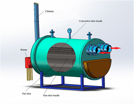
FIGURE 1. Sketch of a gas heater.
Previous research (Guo Y. and Guo Z. X., 2016; Wang, 2017) solely examined the natural convection heat transfer within the cylinder, but the influence of radiation was largely ignored. When radiation and convection effects are of similar importance, a separate calculation of these and superposition without considering their interaction leads to significant errors (Atashafrooz et al., 2015). To have more accurate and reliable results, the flowing fluid must be considered as a radiating medium (Atashafrooz and GandjalikhanNassab, 2013). Because the operating temperature of a water cylinder is usually above 350 K, the radiation between the water, the cylinder, and the tubes must be considered. As a result, water cannot be described as a non-participating medium. Participating medium radiation has become a research hotspot in recent years. However, the majority of research is concentrated on flue gas, with only a few studies focusing on alternative mediums such as water (Smith et al., 1982; Razzaque et al., 1984; Sun et al., 2016; Gao et al., 2019). This research analyzes the coupled heat and flow of natural convection as well as radiation in the cylinder to better understand the heat transfer mode within the gas heater.
Adding metallic plates to enhance convective heat transmission was a frequent method (Guo, 1999; Zhukova and Isaev, 2008; Guo et al., 2011; Sun et al., 2016; Gao et al., 2019). We suggest using a vertical guide plate structure to improve coupled heat transport within a gas heating cylinder.
Mathematical Model
The two-dimensional circular section in the center of a heating cylinder is used as the numerical model in this paper. The configuration information is provided where the heater’s dimensions are given: D1 measures 1,300 mm, D2 measures 325 mm, b1 measures 540 mm, and b2 measures 510 mm. The flue tubes have a diameter of 42 mm and a spacing of 68 mm between adjacent tubes. The convective tubes have a diameter of 38 mm, b3 is 90 mm, b4 is 65 mm, and the angle ϕ is 60°. As illustrated in Figure 2A, there are nine measuring points designated from 0 to eight along the circular section that are used to determine the temperature distribution of the intermediate heating medium in the cylinder. The central temperature of the cylinder is measured at measuring point 0, which is located in the middle of the circular section.
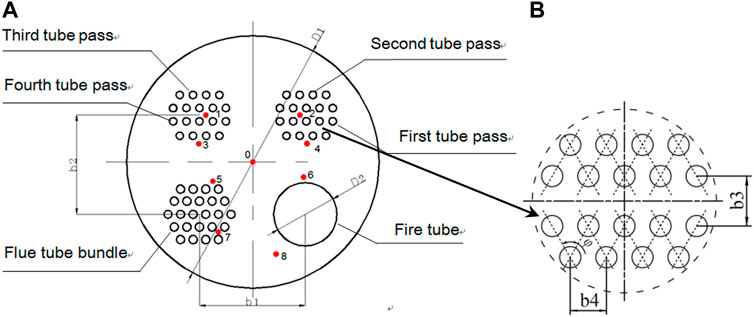
FIGURE 2. (A) Cross-section of a gas heater simulated using a numerical model. (B) A zoom-in of the convective tube bundle.
Measuring point 1 is situated in the third pass area of the convective tube bundle, which is on the left side of the cylinder. Measuring point 2 is on the right side of the cylinder, in the second pass region of the convective tube bundle. The third measuring point is located in the fourth tube pass region on the cylinder’s left side. Point 4 is located on the first tube pass region on the right side of the cylinder. Measuring point 5 is placed in the upper part of the flue tube, while measuring point 6 is situated in the upper part of the fire tube. The lowest half of the flue tube is where measuring point 7 is located, and the bottom of the cylinder is where measuring point 8 is located. Carbon steel is used for the cylinder and all tubes. Interested readers might refer to Guo et al. (Cimina et al., 2015) for further information on the experimental system.
Based on the Boussinesq assumption under steady laminar flow conditions (the maximum Rayleigh number in the present study is about 2.02 × 10⁹; thus, a laminar flow model is considered), the two-dimensional governing equations for the steady-state coupled heat transfer of convection and radiation are as follows:Continuity equation:
Momentum equations:
Energy equation:
Respectively,
where
where
The radiation boundary conditions for the opaque and diffuse wall surfaces are as follows:
The following are the boundary conditions: the adiabatic boundary is the cylinder wall, with the average temperature of the fire tube wall set to 368 K, the average temperature of the flue tube bundle wall set to 363 K, and the convective tube bundle boundary condition expressed as follows:
where n denotes the normal direction of the wall,
The Nusselt number (Nu) is determined using the following equation: the gas inside the convective tube bundle has a thermal conductivity of
The Reynolds number for the gas flow within the convective tubes is Re, and the Prandtl number for the gas flow is Pr.
Fluent 17 was used for numerical simulation in this work, while Gambit software was employed to create hybrid unstructured grids. The convection and radiation-coupled heat transfer in the gas heater are solved using the finite volume approach and discrete ordinate radiation model in Fluent, which is consistent with literatures (Wu et al., 2019), (Aghanajafi and Abjadpour, 2016). Under 350 K, water has an emissivity of 0.922 and an absorption coefficient of 153,679 m−1. The walls of the tubes are assumed to have constant steel characteristics with an emissivity of 0.8, and the thickness of the walls is not taken into account in the simulation.
In the area of the boundary surface, such as around the heating and cooling surfaces, where substantial velocity and temperature gradients exist, mesh refinement is required (Kim and Baek, 1997). Figure 3 depicts a typical grid system as well as a portion of the unstructured grid utilized in computation.
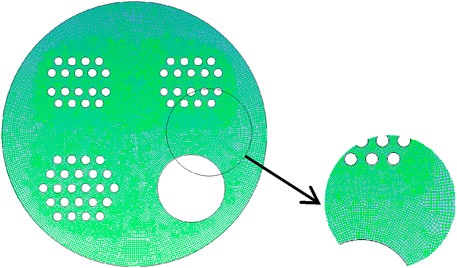
FIGURE 3. A typical grid system.
The grid independency was assessed using five different grid levels, including 136, 232, 423, 875, and 1,170,000 cells: the estimated total heat transfer rate in the convective tube bundle (i.e., the heat utilized to heat up gas inside the convective tubes) is compared to the cylinder’s central temperature in the case without the guide plate in Figure 4. With a finer grid system, the overall heat transfer rate and central temperature converge as predicted. The cumulative heat transfer rate inaccuracy between the finest grid with 1,170,000 cells and the grid with 423,000 cells is less than 0.6%, and the temperature at the cylinder center is less than 0.12%. It can be considered that this and a larger number of grids no longer affect the calculation results; considering the limited resources of the computer, the grid level of 423,000 cells may be employed to conduct research. The same grid-level setting procedure was adopted for all subsequent simulations.
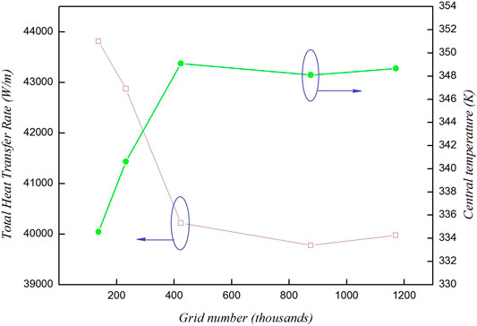
FIGURE 4. Grid independence test of medium water.
Results and Discussion
The experiment was carried out under the boundary conditions specified in the previous article, and the data were read after the measured values of nine points were stable. The temperatures simulated are compared to the experimental results at the nine points highlighted in Figure 2A for the standard cylinder without the use of a guide plate before analyzing the improved heat transfer impact of the vertical guide plate. Figure 5 depicts the contrast. The predicted temperatures agree with the experimental results, indicating that the model and boundary conditions are appropriately adjusted. Due to the neglection of the axial flow and heat dissipation through the cylinder wall in the simulation, the simulated temperatures are generally 1°C∼2°C greater than the corresponding temperatures experimentally measured.
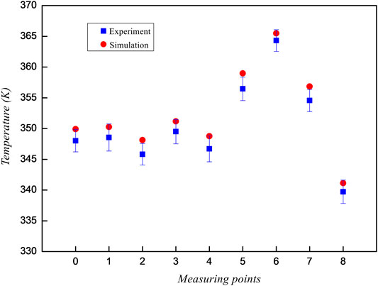
FIGURE 5. Comparison of the simulation and measurement of temperatures at nine locations.
In Figure 5, there is a clear thermal stratification at different heights of cylinder. The temperature is higher at measuring points 5–7 near the fire tube and flue tube bundle. The highest temperature appears at the measuring point 6 nearest to the fire tube. The temperature differences among the measuring points 1–4 at a different convective tube pass are small. The temperature of measuring point 8 at the bottom of the cylinder is the lowest. Obviously, the driving force of the flow field is weak in this traditional cylinder arrangement. So, it took about 4 h for the test to reach a thermal equilibrium condition in the experiment. The start-up of the gas heater was very slow. This indicates the necessity to enhance the efficiency inside the cylinder with modified structures.
A simple and effective heat-transfer improvement option is to install vertical guide plates along the cylinder’s axial path. Subsequently, fluid flow and heat transfer using vertical guide plates of various heights are simulated. The vertical plates are 5 mm thick carbon steel plates. The heights of four plates are compared (350, 450, 550, and 650 mm). As a heating medium, still water is employed.
The temperature and flow fields of the gas heater with a 350 mm vertical guide plate positioned at the upper part are shown in Figures 6A,B. High-temperature zones emerge on the top half of the flue tube bundle and upper left side of the fire tube, as shown in Figure 6A. The water near the flue tube bundle generates an ascending flow that shifts to the left and right; the water near the third and fourth convective tube bundles forms a descending flow, as demonstrated in Figure 6B. The temperature variations among the multireturn of convective tube bundles will cause these two flows to collide and be impacted.
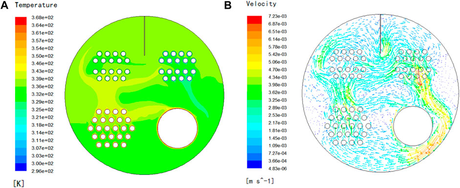
FIGURE 6. A vertical guide plate of 350 mm temperature and flow fields. (A) Isothermal contour (K). (B) Flow vectogram (m/s).
The temperature and flow fields of 450 mm with a vertical guide plate are shown in Figures 7A,B. High-temperature zones arise on the upper part of the flue tube bundle and the upper left side of the fire tube, which can be seen in Figure 7A. Those affections between the first and fourth returns of the convective tube bundle may be observed in Figure 7B.
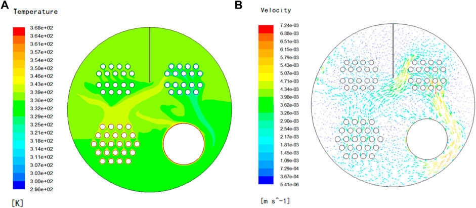
FIGURE 7. 450 mm vertical guide plate temperature and flow fields. (A) Isothermal contour (K). (B) Flow vectogram (m/s).
Figures 8A,B depict the temperature and flow fields of a 550 mm vertical guide plate. High-temperature zones can be seen on the top of the fire tube and flue tube bundle in Figure 8A. Under the diversion of the vertical plate, two flow fields from the center to two sides are generated on the left and right sides of the circular cross-section in the cylinder independently, thus eliminating the collision phenomena.
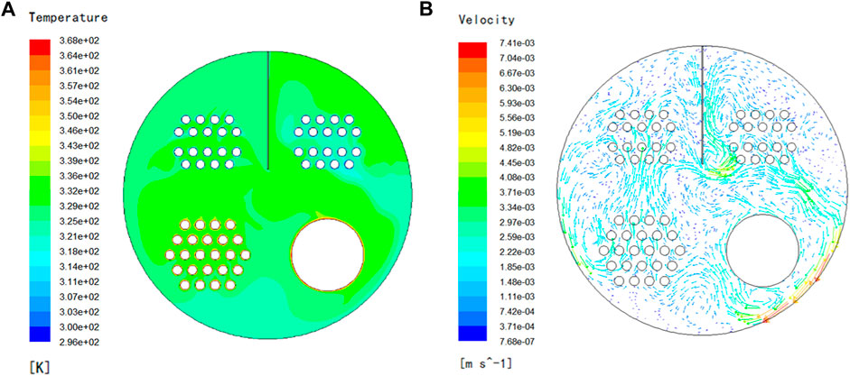
FIGURE 8. 550 mm vertical guide plate temperature and flow fields. (A) Isothermal contour (K). (B) Flow vectogram.
The temperature and flow fields of a 650 mm vertical guide plate are shown in Figures 9A,B. High-temperature zones can be seen on the top-right side of the flue tube bundle and fire tube in Figure 9A. Although two flow fields are generated on both the left and right sides of the circular section in Figure 9B, due to the conflict of opposing water flows, a number of swirl zones are formed, which are not ideal for convective heat transfer.
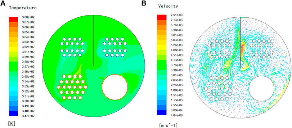
FIGURE 9. 650 mm vertical guide plate temperature and flow fields. (A) Isothermal contour (K). (B) Flow vectogram (m/s).
Figure 10 shows the impact of the vertical guide plate on total heat transfer rates in the convective tube bundle and temperature at the measuring points around the convective tube bundle. Water temperatures surrounding the convective tube bundle without the use of a guide plate are much greater than in circumstances when vertical guide plates are employed. As a result, the construction of the gas heater must be optimized. Due to the varied heights of vertical guide plates, there were differences in the temperature distribution around the multireturn passes of the convective tube bundle. Installing vertical guide plates can lower the overall heat transfer rate of the convective tube bundle by 1.49%–2.04% when heating the gas to the desired temperature. The vertical guide plate with a height of 550 mm has the lowest total heat transfer rate in the convective tube bundle.
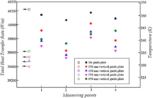
FIGURE 10. The impact of vertical guide plates on total heat transmission and average temperature at the convective tube bundle.
The natural convection heat transfer rates and radiation heat transfer rates for various plate heights are shown in Figure 11. The effect of installing vertical plates on the participating medium radiation is less due to the small temperature difference among the multireturn of the convective tube bundle, but the proportion of radiation heat transfer in the total heat transfer rate still reaches 25.1% by using the vertical guide plate structure, indicating that the part of water radiation is not negligible.
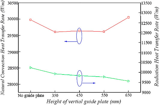
FIGURE 11. Comparison of the rate of natural convection heat transfer and the rate of radiation heat transfer of vertical guide plates with various heights.
Conclusion
The simulated results in this study demonstrated the feasibility and advantages of a heat transfer structure within a gas heater by using vertical guide plates installed along the axial direction of the large cylinder to improve the overall coupled heat transfer efficiency, overcoming the weakness that an effective hot circulating flow field cannot be formed around the cold gas tube inside the conventional gas heater.
Installing vertical guide plates in the midst of the convective tube bundle’s left and right passes might improve natural convection heat transfer while having a minor impact on water radiation. The total heat transfer rate in the convective tube bundle may be lowered by 1.49%∼2.04%. The employment of the vertical guide plate with a height of 550 mm is the optimized case.
Data Availability Statement
The raw data supporting the conclusion of this article will be made available by the authors, without undue reservation.
Author Contributions
All authors listed have made a substantial, direct and intellectual contribution to the work, and approved it for publication.
Funding
This research paper is supported by the China National Natural Science Foundation (No. 51606116) and Shanghai Scientific and Technological Research Projects (No. 19195810800).
Conflict of Interest
ZZ is employed by Shanghai Petrochemical Co., Ltd.
The remaining authors declare that the research was conducted in the absence of any commercial or financial relationships that could be construed as a potential conflict of interest.
Publisher’s Note
All claims expressed in this article are solely those of the authors and do not necessarily represent those of their affiliated organizations, or those of the publisher, the editors and the reviewers. Any product that may be evaluated in this article, or claim that may be made by its manufacturer, is not guaranteed or endorsed by the publisher.
References
Aghanajafi, C., and Abjadpour, A. (2016). Discrete Ordinates Method Applied to Radiative Transfer Equation in Complex Geometries Meshed by Structured and Unstructured Grids. J. Braz. Soc. Mech. Sci. Eng. 38 (3), 1007–1019. doi:10.1007/s40430-015-0397-2
Al-Sammerrai, D. (1985). Study of Thermal Stabilities of Some Heat Transfer Oils. J. Therm. Anal. 30 (4), 763–770. doi:10.1007/BF01913304
Atashafrooz, M., and Gandjalikhan Nassab, S. A. (2013). Simulation of Laminar Mixed Convection Recess Flow Combined with Radiation Heat Transfer. Iranian J. Sci. Techn. 37 (M1), 71–75.
Atashafrooz, M., Nassab, S. A. G., and Lari, K. (2015). Application of Full-Spectrum K-Distribution Method to Combined Non-gray Radiation and Forced Convection Flow in a Duct with an Expansion. J. Mech. Sci. Technol. 29 (2), 845–859. doi:10.1007/s12206-015-0148-4
Cimina, S., Wang, C., Wang, L., Niro, A., and Sunden, B. (2015). Experimental Study of Pressure Drop and Heat Transfer in A U-bend Channel with Various Guide Vanes and Ribs. J. Enh. Heat Transf. 22 (1), 29–45. doi:10.1615/jenhheattransf.2015013382
Gao, B.-H., Qi, H., Yin, Y.-M., Wei, L.-Y., and Ren, Y.-T. (2019). Fast Reconstructing Two-Dimensional Temperature Distribution in Participating Media with Different Surfaces Conditions. Infrared Phys. Techn. 103, 103080. doi:10.1016/j.infrared.2019.103080
Guo, Y., Cao, W.-W., Yan, P., Yu, C.-X., and Qian, S.-Y. (2011). Application and Research Progress of Heater in Natural Gas Industry. Heat Transfer Eng. 32, 1003–1008. doi:10.1080/01457632.2011.556473
Guo, Y., Cao, W. W., Yan, P., and Qian, S. Y. (2009). Exploration and Development of Natural Gas Heaters with High Fuel Efficiency. J. Nat. Gas Ind. 29 (12), 97–100. doi:10.3787/j.issn.1000-0976.2009.12.030
Guo, Y., and Guo, Z. (2016a). Flow and Heat Transfer inside a New Diversion-type Gas Heating Device. Numer. Heat Transfer, Part A: Appl. 70 (1), 1–13. doi:10.1080/10407782.2016.1173441
Guo, Y., and Guo, Z. X. (2016b). A Numerical Study on 2-D Flow and Heat Transfer in A Natural Gas Heater, 2. Washington, DC: ASME Summer Heat Trans. Conf.
Guo, Y. (2012). Investigation on Natural Gas Heater with Different Heat-Transfer Medium. J. Chem. Industry Eng. Prog. 6, 1206–1214.
Guo, Z. (1999). Enhancement of Heat and Mass Transfer in Metal Hydride Beds with the Addition of Al Plates. Heat Mass. Transfer 34, 517–523. doi:10.1007/s002310050290
Kim, M. Y., and Baek, S. W. (1997). Analysis of Radiative Transfer in Cylindrical Enclosures Using the Finite Volume Method. J. Thermophys. Heat Transfer 11 (2), 246–252. doi:10.2514/2.6229
Li, Q. F., and Zhang, G. Z. (2007). Optimal Structural Design of Oil Field Water Bathed Heater. J. China Univ. Pet. 31, 114–118. doi:10.3321/j.issn:1000-5870.2007.03.024
Li, S., and Wang, Y. H. (2019). Transient Simulation and the Minimum Reversal Time of High Temperature Air Combustion in Oil-Field Jacket Heater. J. East. China Univ. Sci. Techn. 1, 1–12. doi:10.14135/j.cnki.1006-3080.20180723008
Razzaque, M. M., Howell, J. R., and Klein, D. E. (1984). Coupled Radiative and Conductive Heat Transfer in A Two-Dimensional Rectangular Enclosure with Gray Participating Media Using Finite Elements. J. Heat Trans. 106 (106), 613–619. doi:10.1115/1.3246723
Setoodeh, H., Keshavarz, A., Ghasemian, A., and Nasouhi, A. (2016). Subcooled Flow Boiling of Ethylene-Glycol/water Mixture in an Inclined Channel with A Hot Spot: An Experimental Study. Int. Commun. Heat Mass Transfer 78, 285–294. doi:10.1016/j.icheatmasstransfer.2016.09.020
Smith, T. F., Shen, Z. F., and Friedman, J. N. (1982). Evaluation of Coefficients for the Weighted Sum of Gray Gases Model. J. Heat Trans. 104 (4), 602–608. doi:10.1115/1.3245174
Su, H. P. (2013). Glycol-water Solution for Heating Process in Oil-Gas Gathering and Transportation. J. Petrochem. Ind. Appl. 32 (4), 97–100. doi:10.3969/j.issn.1673-5285.2013.04.026
Sun, J. J., Yang, J., and Wang, L. L. (2011). Influence Factors of Structure Optimization of Water Jacket Furnace. J. Oil Gas Field Surface Eng. 4, 91. doi:10.3969/j.issn.1006-6896.2011.4.044
Sun, J., Yi, H. L., and Tan, H. P. (2016). Meshless Finite Difference Method for Radiative Transfer in Participating Media. J. Eng. Phys. Thermophys. 37 (3), 653–656.
Wang, Z. (2017). Numerical Study of Natural Gas Water Bath Heater. [Master’s thesis]. Qing dao City (Shan dong Province): China University of Petroleum.
Wu, Z., Shi, Y., Song, K., He, S., and Gao, M. (2019). Numerical Simulation of Heat Transfer Performance Enhancement of Cooling Water Jacket Used in the Carbon Industry. J. Enh. Heat Transf. 26 (3), 235–255. doi:10.1615/JEnhHeatTransf.2019029345
Yuan, B., Yang, D. M., Wang, Y., and Wang, J. R. (2001). Gas Supply Technology for Combustion Gas Generating Unit. J. Oil-Gas Field Surf. Eng. 20 (2), 30–32.
Keywords: gas heater, vertical guide plate, heat transfer enhancement, natural convection, radiation, thermal efficiency
Citation: Guo Y, Zhang X and Zhou Z (2022) Coupled Heat and Flow Analysis Inside a Diversion-Type Gas Heater With Vertical Guide Plate Structure. Front. Energy Res. 10:837104. doi: 10.3389/fenrg.2022.837104
Received: 16 December 2021; Accepted: 22 February 2022;
Published: 11 April 2022.
Edited by:
Jiang Bian, China University of Petroleum, ChinaReviewed by:
Meysam Atashafrooz, Sirjan University of Technology, IranBalaji Kumar, VIT University, India
Copyright © 2022 Guo, Zhang and Zhou. This is an open-access article distributed under the terms of the Creative Commons Attribution License (CC BY). The use, distribution or reproduction in other forums is permitted, provided the original author(s) and the copyright owner(s) are credited and that the original publication in this journal is cited, in accordance with accepted academic practice. No use, distribution or reproduction is permitted which does not comply with these terms.
*Correspondence: Yun Guo, graceguo1980@126.com