Study on a New Environmentally Friendly Synthetic Fluid for Preparing Synthetic-Based Drilling Fluid
 Yuxue Sun1
  Xiuyu Zhu
- 1College of Petroleum Engineering, Northeast Petroleum University, Daqing, China
- 2Drilling Engineering Technology Research Institute, Daqing Drilling Engineering Company, Daqing, China
- 3College of Mechanical and Electrical Engineering, Guangdong University of Petrochemical Technology, Maoming, China
In view of the pollution problems related to using oil-based drilling fluids, we prepared a new environmentally friendly synthetic fluid, namely, NSF, for use in synthetic-based drilling fluid instead. We used heavy hydrocarbons from Daqing as raw material in our preparation and employed few-steps refining techniques, such as hydrodesulfurization, hydrodearomatization, and hydrogenation. After the treatment, the sulfur and aromatic hydrocarbon contents in the NSF were <0.5 mg/L, meeting international environmental standards. NSF is composed mainly of C12-C22 hydrocarbons, and is characterized by low impurity content, small specific gravity, and easy degradation. In addition, the LC50 value is >1,000,000 mg/L water-soluble fraction; therefore, its toxicity is <10% of that of diesel in oil-based drilling fluid and, as the flash point of NSF is about 134°C, the related fire hazard is low. The synthetic-based drilling fluid with NSF has the advantage of causing no swelling damage to the reservoir, and saves the cost of drilling fluid because it doesn't need to deal with the environmental problems (the sulfur and aromatic hydrocarbon contents were <0.5 mg/L) and field problems caused by the reaction between drilling fluid and reservoir, and greatly increases the ROP through reducing the drill pipe sticking and with C12-C22 hydrocarbons in synthetic-based fluid, and safely uses, and has stable drilling fluid performances which are flash point (134°C) and low fire hazard. We have therefore achieved our aim of preparing a high-quality and non-toxic synthetic fluid, of which the aromatic hydrocarbon and sulfur contents meet international standards. Using this synthetic-based drilling fluid therefore facilitates environment protection drilling.
Introduction
The drilling fluids that commonly used in the oil field can be divided into water-based drilling fluid, oil-based drilling fluid and synthetic-based drilling fluid according to their properties. Water-based drilling fluid is one of the earliest used systems in drilling. And with the increasing complexity of drilling conditions, water-based drilling fluids with high temperature resistance, high density, and strong inhibitor are gradually studied, such as using nanomaterials to replace KCl and produce a new kind of inhibitor which can reduce drilling and disposal cost. Also, some researchers reported a novel kind of water-soluble acrylic acid grafted activated carbon and Cetyltrimethylammonium modified grapheme which can also reduce water invasion and protect the clay from water. However, for drilling long sections in wellbore, it still can cost much and cause environmental problems. Therefore, it is always a problem to find biogradable materials and nanomaterials which are good for environment and reservoir (Saleh and Ibrahim, 2019; Ibrahim and Saleh, 2020; Rana et al., 2020).
What's more, oil-based drilling fluid that is used to replace the water-based drilling fluid has good performance, it can cost much, about as three times as water-based drilling fluid, and, its use remains limited because of the attendant pollution problems. However, in recent years, the use of gas-based oil instead of ordinary diesel as base oil has alleviated the pollution problems, but the production process is complex and expensive. Moreover, natural gas is scarce in China; consequently, using this type of base oil is not suitable for our country (Yan, 2001; Perry and Lee, 2007; Hao, 2015; Xie, 2017). In order to meet the environmental requirements, synthetic drilling fluid which can replace traditional oil-based drilling fluid is increasingly popular and widely used in fields. Synthetic based drilling fluid regards synthetic fluid as continuous phase and brine or water as dispersed phase. Moreover, the synthetic-based fluid is a relatively pure material without low molecular weight components. Therefore, it is less toxic and can be biodegraded under aerobic and anaerobic conditions, which is less harmful during fluid treatment. The performance of synthetic drilling fluid is similar to that of oil-based drilling fluid, but it is safe to use and has little environmental pollution (Candler et al., 1993; Patel, 1998).
Therefore, the aim of this study was to prepare a low-cost, high-quality, non-toxic synthetic fluid, namely, NSF, of which the aromatic hydrocarbon and sulfur contents meet international standards. We employed hydrogenation and catalytic oxidation technology and used heavy hydrocarbons from Daqing to prepare this new synthetic fluid and synthetic-based drilling fluid that is not only environmentally friendly but also has strong practicability.
Materials and Methods
Preparation of Materials and Process Equipment
Materials
The physicochemical index of the heavy hydrocarbons we used as raw material are (1) a distillation range of 80–280°C, (2) condensation point of−20 to−40°C, (3) flash point of 30–50°C, (4) sulfur content of 250 mg/L, (5) aromatic hydrocarbon content of 6–8%, and (6) alkene content of 2–3%.
Equipment
As shown in Figure 1, the equipment included (1) a stock cushion tank, (2) heating furnace, (3) fractionating tower, (4) first-order hydrogenation reactor, (5) mesothermal temperature zinc oxide sweetener A, (6) mesothermal temperature zinc oxide sweetener B, (7) second-order hydrogenation reactor, (8) cooling extractor, (9) stock hydrocarbons pump, (10) third heat exchanger, (11) supercharged pump, (12) second heat exchanger, (13) first heat exchanger, and (14) a condenser.

Figure 1. Process flow diagram of NSF synthetic fluid preparation.
Process
After fractionation, hydrogenation, desulfurization and aromatization, cooling, and other processes, the aromatic content of the final synthetic fluid was <0.5 mg/L and the sulfur content was also <0.5 mg/L. This means that the quality of this fluid was consistent with the accepted standards. The main processes are as follows.
(1) Fractionation
The heavy hydrocarbons in the stock cushion tank (1) is transported by the stock hydrocarbons pump (9), in turn, with the second hydrogenation-generated fluid of the second-order hydrogenation reactor (7) to exchange the heat in the first heat exchanger (13) and, subsequently, into the second heat exchanger (12) to exchange the heat with the generated fluid (220°C). After mesothermal temperature zinc oxide fine desulfurization (220°C), it is transported into the third heat exchanger (10) to exchange the heat with the solvent oil (200# naphtha), which is separated from the fractionator (3). Finally, the agent fluid is heated to the separation temperature (200–260°C) with the heating furnace (2) and transported into the fractionator (3). After the agent fluid is separated from the fractionator (3), the clean gasoline is obtained at the top of the fractionating tower and the 200# naphtha is measured in the tower. The bottom fluid of the fractionating tower is transported to the first hydrogenation reactor (4) at a pressure of 0.5 MPa, with the supercharged pump (11).
(2) First hydrogenation
The additional hydrogen supplied by the compression device is mixed with the bottom fluid before being pumped by the supercharged pump (11), and the mixture of bottom fluid and hydrogen enters the first-order hydrogenation reactor (4) from the upper part of the tower. In this process, the mixture of bottom fluid and hydrogen is always in the condition of 200–260°C and 0.5 MPa. Next, the hydrogenation reaction is conducted at a temperature of 200–220°C, pressure of 0.5 MPa, and airspeed of 1 h−1, under the existence of catalyst, the sulfide in oil reacts with hydrogen, and after once of this process, the organic sulfur at the bottom of the tower is converted into H2S, and most of the alkenes are converted into alkanes. The amount of this process is depend on if the sulfur content meets the demand of standard which is 0.5 mg/L, if not, repeat the process again. The first-order hydrogenated synthetic fluid is discharged from the bottom of the first-order hydrogenation reactor (4) into the zinc oxide desulfurization sweetener.
(3) Zinc oxide desulfurization
The H2S from the first-order hydrogenated synthetic fluid is then reduced to <0.5 mg/L in the zinc oxide sweetener through the reaction between H2S and ZnO, the temperature is controlled at 200–220°C and the pressure is 0.5 MPa. After this period, and the generated synthetic fluid after desulfurization is transported into the second hydrogenation reactor (7) under 200–220°C and 0.5 MPa.
(4) Second hydrogenation
The hydrodearomatization is conducted at a temperature of 120–160°C, pressure of 0.5 Mpa, and airspeed of 1 h−1 in the second-order hydrogenation reactor (7), the arene reacts with hydrogen and is converted into alkane and cycloalkane. Subsequently, after second-order hydrogenation, the generated synthetic fluid and excess hydrogen are discharged from the bottom of the second-order hydrogenation reactor (7) to the first heat exchanger (13).
(5) Cooling and separation
The second-order hydrotreated synthetic fluid enters the condenser (14) after heat exchange in the first heat exchanger (13) with the stock heavy hydrocarbons and, subsequently, enters the cooling separator (8) after cooling at the condenser (14). The final product is obtained after gas–liquid separation in the cooling separator (8). The final product is transported to the product cushion tank if the synthetic fluid product satisfies the demand of both aromatics and sulfur content being <0.5 mg/L. The fluid in the product tank is the synthetic fluid of the environmentally friendly drilling fluid. If the content of aromatics and sulfur are not below the standard condition (0.5 mg/L), repeat the above process. The hydrogen is compressed by the circulating hydrogen compressor after mixing the circulating hydrogen from the cooling separator (8) and the supplemental hydrogen and, subsequently, it is transported to be mixed with the raw material or to be used as cold hydrogen.
Desulfurization and Dearomatization Experiment
In this experiment, the sulfur content in the raw material was sorted into thiol, sulfur ether, and sulfur dioxide, which have high aromatics content, as shown in Table 1.
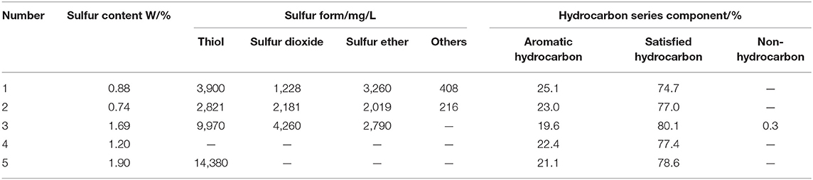
Table 1. Nature of hydrocarbons in the laboratories.
Thiol and sulfur dioxide are both active sulfides with unpleasant odor, are significantly corrosive to Cu metal, and can reduce the stability of oil products. Sulfur ether is inactive sulfide, but it is also corrosive. The sulfur oxides produced by the combustion of these three sulfurs cause environmental pollution. Furthermore, if the aromatic content is too high, the drilling fluid will be highly toxic and will cause serious pollution. The international standards for sulfur and aromatics contents are shown in Tables 2, 3, and the classification criteria for toxicity are shown in Table 4.
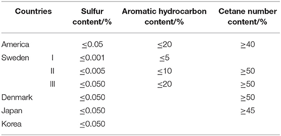
Table 2. The new criterions of hydrocarbons.
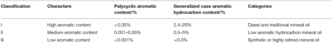
Table 3. The international association of oil and gas production for the classification of drilling fluid system.
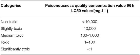
Table 4. The classification of toxicity.
We compared the synthetic fluid of the drilling fluid required particularly for the exploitation of shale formations with the above criteria, finding that the conventional raw material has both high sulfur and high aromatic contents. Therefore, to improve the material to be used as synthetic fluid in drilling fluid, it needed to be desulfurized and dearomatized.
Desulfurization Experiment
Catalytic cracking was used in this experiment, as it can convert the organic sulfur compounds in the stock hydrocarbons into hydrogen sulfide, which escapes in the form of gas. Subsequently, the performance of the stock hydrocarbons could be improved by catalytic oxidation, after it meets the above standards (Wu, 2000; Zhang et al., 2018).
Experimental Principles
Catalytic cracking desulfurization is essentially the carbon-sulfur bond in the organic sulfide molecule being broken by the catalyst (acidic condition) to form hydrogen sulfide, changing the original form of the sulfur, after which it is removed (Liao et al., 1999; Parkinson, 2000). The stock hydrocarbons forms gas, synthetic fluid, oil, and coke during the catalytic cracking, and some coke is deposited onto the surface of the catalyst. As the carbon deposition increases, the activity of the catalyst decreases, eventually leading to a decrease in the desulfurization rate. At this point, regeneration of the catalyst is carried out, meaning that the original reaction is stopped, and the steam mixture is used to burn the carbon deposit, thereby restoring the activity of the catalyst (Wang et al., 2009; Halbert and Greeley, 2000). The relevant equations are as follows and the process flow diagram is shown in Figure 2.
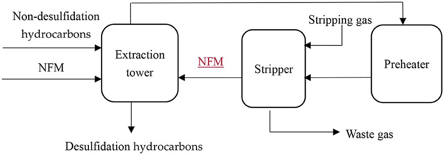
Figure 2. Desulfurization process flow diagram.
Experimental Conditions
The reaction conditions of the experiments were controlled, and the experiments were conducted at airspeeds of 1.0, 2.0, and 3.0 h−1, respectively. Each group of airspeeds was tested at different temperatures, namely, 380, 430, 480, and 530°C, as shown in Table 5.
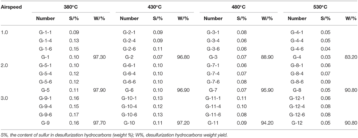
Table 5. Hydrocarbons and catalyst desulfurization experiment.
As Table 5 shows, at a certain airspeed, the sulfur content of the desulfurized fluid decreases as the temperature increases, with the fluid yield decreasing as well. In this instance, the fluid yield was not ideal and, to improve the desulfurization effect, the procedure would have to be conducted at a higher temperature and lower airspeed. Therefore, the conditions we chose were 2.0 h−1 and a temperature of 480°C.
Experimental Results
The properties of the stock hydrocarbons after catalytic desulfurization are shown in Table 6, which indicates that the cracking reaction occurs simultaneously with desulfurization.
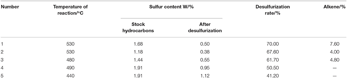
Table 6. Properties of raw material after desulfurization.
As Table 6 shows, at a certain airspeed, the desulfurization rate increases as the temperature increases, and the higher temperature, the lower the gap of desulfurization rate.
After the catalytic desulfurization, the sulfur content of the stock hydrocarbons remained high; therefore, further experiments were conducted employing catalytic oxidation to remove more thiols from the sulfur. The catalytic oxidation experiments require two procedures, namely, extraction and deodorization (Basu et al., 1993; Ji, 2013; Xie, 2014). In the extraction experiment, the catalyst was dissolved in the lye and mixed with the hydrocarbons. The thiol reacted to form sodium thiolate and separated from the hydrocarbons and, subsequently, air was added to oxidize the sodium thiolate to form a disulfide precipitate, which was then separated. The relevant equations are as follows:
Afterward, deodorization was carried out, with the thiol converted into disulfide, whereas the total sulfur content remained unchanged. The thiol was removed after being extracted and deodorized. In this experiment, sulfonated asphalt was used as the catalyst under atmosphere pressure and at the temperature of 25°C. The relevant equations are as follows and the deodorization is shown in Figure 3.
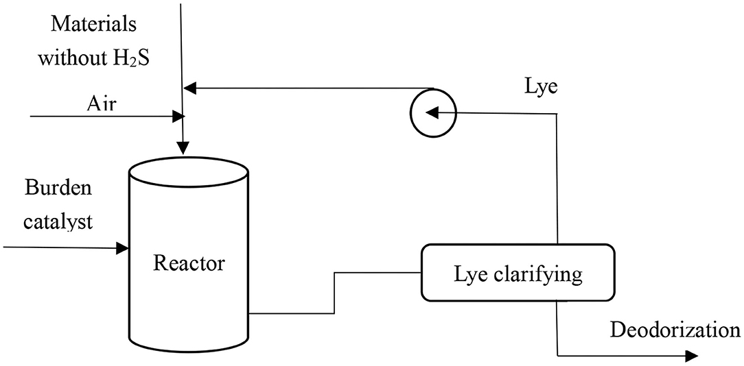
Figure 3. Conventional deodorization process under atmospheric pressure and 25°C.
Dearomatization Experiment
The stock hydrocarbons was treated further in a hydrodearomatization experiment. The hydrogenation of aromatic hydrocarbon compounds is reversible (Xie, 2014). The equation is as follows:
Where A is the aromatic hydrocarbon compound and AH is the product of hydrogenation, i.e., cycloalkane.
The equilibrium concentration of the aromatic hydrocarbon compounds is expressed under the following conditions, namely, that the liquid-phase activity factor of the aromatic hydrocarbon compound A and the cycloalkane AH are equal to the fugacity, the hydrogen activity coefficient to the total pressure ratio is 1, and the hydrogen fugacity to the total pressure ratio is 1.
Where yA is the aromatic hydrocarbon mole fraction, yAH is the cycloalkane mole fraction, KA is the equilibrium constant, and PH2 is the hydrogen differential pressure.
Higher pressure is beneficial to decreasing the equilibrium concentration of aromatic hydrocarbon and increasing its conversion rate. In the process of aromatic hydrocarbon hydrogenation, 63–71 A/kJ·mol−1 heat is released continuously. The equilibrium constant Ka decreases, and the equilibrium conversion rate decreases with the increase in reaction temperature. Therefore, a lower temperature is more conducive to the reaction, so that benzene and toluene are converted maximally into saturated cyclohexane and saturated methylcyclohexane (Wang et al., 2013; Wang, 2015; Chen et al., 2020).
Through Table 7, as the hydrogenation kinetics of polycyclic aromatic hydrocarbons (PAHs) follow the “cyclic hydrogenation principle,” the hydrogenation rate of the PAHs decreases in turn, with the first cyclic hydrogenation being the fastest and the last aromatic hydrogenation being slower than that of the monocyclic aromatic hydrocarbons. Consequently, there are more monocyclic aromatics and monocyclic cycloalkane in hydrocracking products. It can be concluded that benzene and hydrogen produce cyclohexane, which can improve the yield of aromatic hydrocarbon hydrogenation effectively under low-temperature and high-pressure conditions.
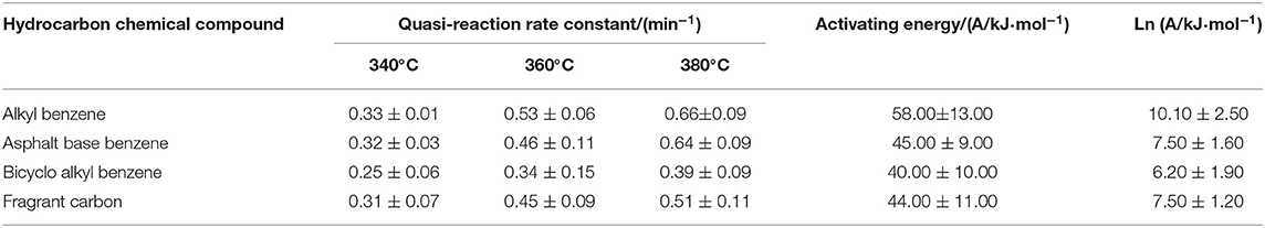
Table 7. The aromatics hydrogenation kinetic parameters under different reaction conditions.
The comparison and evaluation results of the density, viscosity, and flash point of various synthetic fluids after desulfurization and dearomatization are shown in Table 8.
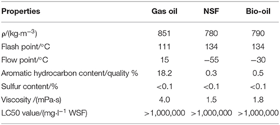
Table 8. The performance of the base fluid data sheet.
Results
Our newly prepared NSF is composed mainly of C12-C22 hydrocarbons with a low impurity content, low specific gravity, low water content, easy volatilization, and easy degradation.
Number of Carbon Atoms in NSF
As shown in Figure 4, the C12-C22 content of carboatomic numberin NSF is more than 90%.

Figure 4. Number of carbon atoms in NSF under ambient condition.
KV of NSF
As shown in Figure 5, the kinematic viscosity (KV) of NSF is low, and the viscosity of NSF decreases with the increase in temperature.
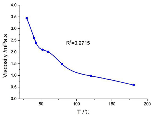
Figure 5. Viscosity with temperature change curve under atmospheric pressure.
Density of NSF
As shown in Figure 6, the density of NSF is affected significantly by temperature, e.g., with an increase in the temperature, the density of NSF decreases.
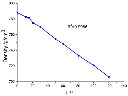
Figure 6. Density changing with temperature curve under atmospheric pressure.
Compressibility of NSF
As shown in Figure 7, as the temperature increases, the compressibility of NSF increases. And the higher the pressure, the smaller the diffenerce between compressions.
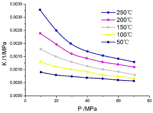
Figure 7. Compression performance change under different temperature and pressure.
Discussion
To ensure that the performance of the synthetic-based drilling fluid with the designed synthetic fluid meets the drilling requirements, a synthetic based drilling fluid is formulated with additives, such as viscosifier, emulsifier, and fluid loss control agent, etc. The formula is as follows:
250 mL synthetic fluid + 20% brine (5% CaCl2) + 3% emulsifier + 3% viscosifier + 2% wetting agent (WETA-2) + 3% acryl resin + lime + barite.
Rheological Property of Synthetic-Based Drilling Fluid
Laboratory experiments on the rheological property of the drilling fluid with different densities are conducted. Our experimental results showed that the synthetic-based drilling fluid has good rheological property and a low filtration rate.
As shown in Table 9, the synthetic-based drilling fluids with different densities have good rheological property and low medium pressure filtration, which can improve the rate of penetration effectively.
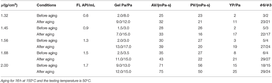
Table 9. Performance of synthetic-based drilling fluid under different density.
Sag Stability of Synthetic-Based Drilling Fluid
Synthetic-based drilling fluid, with a density of 1.50 g/cm3 was aged at 150°C for 16 h, and the density difference between the upper and lower parts of the drilling fluid in the beaker was measured after holding for 24 h. The results showed that the density of the upper drilling fluid was 1.49 g/cm3 and that of the lower was 1.52 g/cm3, indicating that the synthetic fluid had not precipitated. Accordingly, the synthetic-based drilling fluid has excellent suspension property.
As shown in Table 10, under a simulated down hole temperature condition, the viscosity and shearing force of the drilling fluid increased with an increase in the resting time. The drilling fluid showed good shear thinning property, strong suspension force, and solid carrying capacity, and could meet various operating requirements under pump-off conditions.
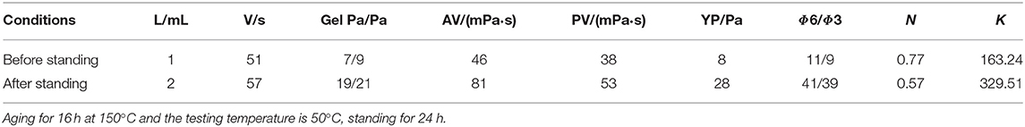
Table 10. ρ = 1.50 g/cm3 density of drilling fluid performance comparison before and after high temperature standing.
Electric Stability of Synthetic-Based Drilling Fluid
Synthetic-based drilling fluids with different densities were used to determine the electric stability (Kirsner et al., 2005; Yi et al., 2008), as shown in Table 11. The demulsification voltage of these drilling fluids at different densities was more than 2,000 V, indicating that the system has good electric stability.
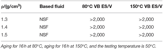
Table 11. Different drilling fluid density electric stability.
As shown in Table 11, the densities of the drilling fluid that we choose are 1.3, 1.4, and 1.5 g/cm3 and no matter what the density condition is, the demulsification voltage under 80 and 150°C is always higher than 2,000 V, which shows a good electric stability.
Reservoir Protection Performance of Synthetic-Based Drilling Fluid System
The core of Rang 53 Block was selected to evaluate the performance of synthetic-based drilling fluid through laboratory experiments. The procedure s are as follows: after choosing the core, first, determining the permeability of rock samples with air; next, vacuuming the rock sample and saturate it with formation water, and displacing it with kerosene under until the formation reaches irreducible water under the pressure difference between confining pressure and inlet pressure of 1.5–2.0 MPa, then measuring the positive permeability (K0). Finally, pumping the different drilling fluids from the negative part, and then measuring the positive permeability (K1) with kerosene after damaging. The ratio of K1 to K0 is the permeability recovery values. All of the above process is implemented under ambient temperature for about 120 min. The drilling fluid affected the reservoir in both solid and liquid phases, i.e., the invasion of the solid particles and the invasion of the filtrate (Zhang et al., 2017; Zhang, 2018). The permeability recovery value is an index for evaluating the degree of reservoir damage. Different drilling fluid systems were selected to determine the permeability recovery values. The experimental results under atmospheric conditionare shown in Table 12.
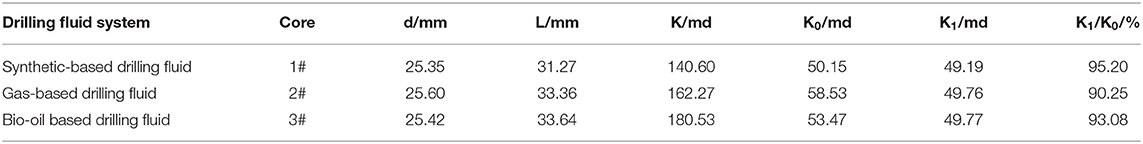
Table 12. Different pollution system core permeability recovery value.
As shown, the permeability recovery value of a conventional drilling fluid system is kind of low, and the damage to the formation is significant, i.e., it is blocked and polluted easily. However, the core permeability recovery value of the synthetic-based drilling fluid system is more than 95%, the filtration rate is low, and reservoir protection effect is good.
Dynamic Filtration Evaluation of Synthetic-Based Drilling Fluid
Dynamic filtration experiments with the synthetic-based drilling fluid, gas-based drilling fluid, and bio-oil based drilling fluid are carried out. The procedures are as follows: drilling fluid is poured into the mud tank of the dynamic filtration simulator and heated. When the temperature reaches 5–10°C below the experimental temperature, the motor is turned on to the required speed. When the temperature is constant, the filtration volume is recorded until the dynamic filtration is in equilibrium. Then, the experiment is stopped (Zhang et al., 2016; Gong et al., 2017). The results are shown in Table 13.
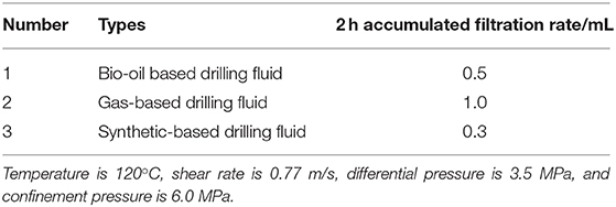
Table 13. The dynamic filtration experiment results.
As shown in the Table 13, when the drilling fluid is immersed in the formation too long, less dynamic filtration of the synthetic-based drilling fluid occurs and the filtrate entering the formation is insignificant, which is beneficial to wellbore stability.
Conclusions
(1) Designed synthetic fluid is obtained from stock hydrocarbons by fractionation, hydrogenation, desulfurization, dearomatization, cooling, and other processes. NSF is composed mainly of C12-C22 hydrocarbons, with low impurity contents, small specific gravity, and easy degradability. The LC50 value of treated synthetic fluid is >1,000,000 mg/L WSF, and its toxicity is <1/10 of that of diesel. The flash point of NSF is above 134°C, the safety is high, and the aromatic hydrocarbon content of synthetic fluid is therefore significantly lower than is that of other synthetic fluid, such as bio-oil.
(2) We evaluated NSF systematically in the laboratory, with the results indicating that the properties of the designed NSF being clearly superior to those of other synthetic fluid. It is the preferred synthetic fluid for preparing environmentally friendly drilling fluid systems because of its high permeability recovery value which is 95.2%, excellent suspension property which with the upper drilling fluid was 1.49 g/cm3 and that of the lower was 1.52 g/cm3, minor dynamic filtration which is 0.3 mL in 2 h, and insignificant pollution of the reservoir.
(3) The prepared NSF is a quality product that does not cause pollution to the environment. This new synthetic-based drilling fluid is not only environmentally friendly but also its performance is superior and economic, because it can improve the rate of penetration without inducing borehole problems. We have therefore achieved our aim of preparing a kind of low-cost, high-quality, non-toxic synthetic fluid, of which the aromatic hydrocarbon and sulfur contents meet international standards. Using this synthetic-based drilling fluid therefore facilitates environment protection drilling.
Data Availability Statement
All datasets generated for this study are included in the article/supplementary material.
Author Contributions
YS: conceptualization, resources, and supervision. XZ and JZ: methodology. XZ and DS: validation and data curation. YS and JZ: formal analysis. XZ: investigation. YS and XZ: writing—original draft preparation and visualization. YS, XZ, and JZ: writing—review and editing. All authors contributed to the article and approved the submitted version.
Conflict of Interest
The authors declare that the research was conducted in the absence of any commercial or financial relationships that could be construed as a potential conflict of interest.
Acknowledgments
This work was supported by the laboratory of oil and gas layer protection of the Northeast Petroleum University and the author would like to thank the help of professor. What's more, we would like to thank Editage [www.editage.cn] for English language re-editing.
References
Basu, B., Satapathy, S., and Bhatnagar, A. K. (1993). Merox and related metal phthalocyanine catalyzed oxidation processes. Cataly. Rev. Sci. Eng. 35, 571–609. doi: 10.1080/01614949308013917
Candler, J. E., Rushing, J. H., and Leuterman, A. J. J. (1993). “Synthetic-based mud systems offer environmental benefits over traditional mud systems,” in SPE/EPA Exploration and Production Environmental Conference (San Antonio, TX: Society of Petroleum Engineers).
Chen, R. L., Gao, X. D., Shi, Y. L., and Nie, H. (2020). Study on deep dearomatization of FCC diesel oil by hydrogenation. Petrol. Process. Petrochem. 2002, 6–10.
Gong, M., Zhan, X. B., and Zhai, Y. M. (2017). Influence and preventive measures of shale swelling on casing. Petrochem. Technol. 24, 224–277.
Halbert, T. R., and Greeley, J. P. (2000). “Technology options for meeting low sulfur targets,” in NPRA Annual Meeting (San-Antonio, TX). snl, AM-00-11.
Hao, C. (2015). Study on Oil-Based Drilling Fluid of Shale Gas Horizontal Well in Longmaxi Formation in Weiyuan Area. Chengdu: Southwest Petroleum University.
Ibrahim, M. A., and Saleh, T. A. (2020). Partially aminated acrylic acid grafted activated carbon as inexpensive shale hydration inhibitor. Carbohydr. Res. 2020:107960. doi: 10.1016/j.carres.2020.107960
Ji, Q. N. (2013). Effection of oxidative desulfurization of diesel fuel by Ce, La–loaded aluminum oxide. Guangzhou Chem Ind. 41, 95–96.
Kirsner, J., Siems, D., Burrows-Lawson, K., and Carbajal, D. H. (2005). Method of Formulating and Using a Drilling Mud With Fragile Gels. Houston, TX. U.S. Patent. 6,887,832.
Liao, J., Liu, B. H., and Yao, G. X. (1999). Technical advances in diesel biodesulfurization. . Petrol. Refinery Eng. 29, 15–19.
Patel, A. D. (1998). “Choosing the right synthetic-based drilling fluids: drilling performance versus,” in SPE India Oil and Gas Conference and Exhibition (New Delhi: Society of Petroleum Engineers).
Perry, K., and Lee, J. (2007). Unconventional gas reservoirs: tight gas, coal seams, and shale . Work. Doc. NPC Glob. Oil Gas Study 18:14.
Rana, A., Arfaj, M. K., Yami, A. S., and Saleh, T. A. (2020). Cetyltrimethylammonium modified graphene as a clean swelling inhibitor in water-based oil-well drilling mud. J. Environ. Chem. Eng. 2020:103802. doi: 10.1016/j.jece.2020.103802
Saleh, T. A., and Ibrahim, M. A. (2019). Advances in functionalized nanoparticles based drilling inhibitors for oil production. Energy Rep. 5, 1293–1304. doi: 10.1016/j.egyr.2019.06.002
Wang, C. M., Tsai, T. C., and Wang, I. (2009). Deep hydrodesulfurization over Co/Mo catalysts supported on oxides containing vanadium. J. Catal. 262, 206–214. doi: 10.1016/j.jcat.2008.12.012
Wang, F. J., Zhang, Y. Y., Long, X. Y., and Gao, X. D. (2013). Study on increasing cetane number of FCC diesel oil fractions by hydrofinning. Petrol. Process. Petrochem. 44, 27–31.
Wang, L. Q. (2015). Studies on a Process for Demercaptaning of Fluid Catalytic Cracked Naphtha (FCCN) in Combination with Hydrotreating Technonogy. Shanghai: East China University of Science and Technology.
Xie, L. (2014). The Development and Application of New Gasoline Hydrogenation Desulfurization Technology. Hefei: Hefei Polytechnic University.
Xie, Y. N. (2017). Experimental study on low-toxicity and environment-friendly oil-based drilling fluids. Petrol. Drill. Techniq. 45, 45–50.
Yi, X., Goodman, H. E., Williams, R. S., and Hilarides, W. K. (2008). “Building a geomechanical model for Kotabatak field with applications to sanding onset and wellbore stability predictions,” in IADC/SPE Asia Pacific Drilling Technology Conference and Exhibition (Jakarta: Society of Petroleum Engineers).
Zhang, G., Chen, H. Z., and Gao, W. (2016). Research and countermeasures of hard brittle shale borehole instability in Tahe sidetracking horizontal well. Drill. Prod. Technol. 39, 4–7.
Zhang, X. F., Zhang, J. R., and Zhu, Y. J. (2018). Research progress on oxidation of diesel sulfide. Modern Salt Chem. Ind. 45, 11–12.
Zhang, X. L. (2018). The evaluation method for the invasion depth of the filtrate of drilling fluids. Guangdong Chem. Ind. 45, 41–42.
Keywords: hydrogenation technology, performance evaluation, synthetic fluid, environmentally friendly, synthetic-based drilling fluid
Citation: Sun Y, Zhu X, Zhao J and Sui D (2020) Study on a New Environmentally Friendly Synthetic Fluid for Preparing Synthetic-Based Drilling Fluid. Front. Chem. 8:539690. doi: 10.3389/fchem.2020.539690
Received: 02 March 2020; Accepted: 20 November 2020;
Published: 14 December 2020.
Edited by:
Guang Zhao, China University of Petroleum (Huadong), ChinaReviewed by:
Tawfik A. Saleh, King Fahd University of Petroleum and Minerals, Saudi ArabiaQiang Wei, China University of Petroleum, China
Copyright © 2020 Sun, Zhu, Zhao and Sui. This is an open-access article distributed under the terms of the Creative Commons Attribution License (CC BY). The use, distribution or reproduction in other forums is permitted, provided the original author(s) and the copyright owner(s) are credited and that the original publication in this journal is cited, in accordance with accepted academic practice. No use, distribution or reproduction is permitted which does not comply with these terms.
*Correspondence: Xiuyu Zhu, 1746079929@qq.com