Techno-Economic Analyses of the CaO/CaCO3 Post-Combustion CO2 Capture From NGCC Power Plants
 Chao Fu
 Simon Roussanaly
 Kristin Jordal
  Rahul Anantharaman
- SINTEF Energy Research, Trondheim, Norway
Calcium looping is a post-combustion technology that enables CO2 capture from the flue gases of industrial processes. While considerable studies have been performed at various levels from fundamental reaction kinetics to the overall plant efficiency, research work on techno-economic analyses of the calcium looping processes is quite limited, particularly for the Natural Gas Combined Cycle (NGCC). Earlier work has shown that theoretically, a high thermal efficiency can be obtained when integrating calcium looping in the NGCC using advanced process configurations and a synthetic CaO sorbent. This paper presents an investigation of calcium looping capture for the NGCC through a techno-economic study. One simple and one advanced calcium looping processes for CO2 capture from NGCC are evaluated. Detailed sizing of non-conventional equipment such as the carbonator/calciner and the solid-solid heat exchanger are performed for cost analyses. The study shows that the CO2 avoided cost is 86–95 €/tCO2, avoided, which is considerably more expensive than the reference amine (MEA) capture system (49 €/tCO2, avoided). The calcium looping processes considered have thus been found not to be competitive with the reference MEA process for CO2 capture from NGCC with the inputs assumed in this work. Significant improvements would be required, for example, in terms of equipment capital cost, plant efficiency and sorbent annual cost in order to be make the calcium looping technology more attractive for capturing CO2 from NGCC plants.
Introduction
Carbon Capture and Storage (CCS) is an economically competitive technology for CO2 mitigations in the 450 Scenario (IEA, 2015). The power sector is expected to be responsible for around 60% of the cumulative investment in CCS to 2040. Among various CO2 capture technologies, post-combustion capture using amine-based solvents is the most mature technology and is currently being demonstrated at large scale at different sites according to the Global CCS Institute (2016). However, other post-combustion technologies such as membranes, low-temperature, adsorption and absorption using more advanced solvents (Figueroa et al., 2008), have also been being investigated to further reduce the cost of CO2 capture to an acceptable level. CaO/CaCO3 looping or calcium looping (CaL) has been regarded as a promising alternative that is expected to achieve lower capture cost (Hanak et al., 2015) and avoid the emissions of potentially toxic chemical residues (Berstad et al., 2012). Increasing studies have been performed on CaL at different levels including experiments on reaction kinetics and sorbent performance enhancement (Grasa et al., 2008; Fang et al., 2009; Rodríguez et al., 2010; Martínez et al., 2012), reactors (carbonator/calciner) modeling (Alonso et al., 2009; Romano, 2012; Ylätalo et al., 2012; Martínez et al., 2013), pilot facilities test (Arias et al., 2013; Kremer et al., 2013; Dieter et al., 2014) and process simulation and system energy performance evaluation (Yang et al., 2010; Martínez et al., 2011; Berstad et al., 2012; Berstad et al., 2014; Ylätalo et al., 2014). More details can be referred to the comprehensive reviews (Hanak et al., 2015; Martínez et al., 2016; Perejón et al., 2016).
Due to large CO2 emissions from coal-fired power plants, most of CaL studies have focused on coal based power generation. Only a few studies (Berstad et al., 2012; Berstad et al., 2014; Cormos, 2015) have been performed for natural gas combined cycles (NGCC) which have lower CO2 concentration in the exhaust (∼4 vol% according to (Anantharaman et al., 2011)). The carbonation reaction is operated around 600 °C (Hanak et al., 2015). This temperature is close to the exhaust flue gas temperature of gas turbines. From a thermodynamic point of view, the CaL system therewith appears to have a possibility for efficient integration into the NGCC. Simulation studies (Berstad et al., 2012) on the entire NGCC with CO2 capture found that a basic CaL process using natural limestone sorbent resulted in a larger energy penalty than CO2 capture with amine solvents such as MEA (monoethanolamine). However, a subsequent study (Berstad et al., 2014) concluded that there is a large efficiency improvement potential for the CaL process. For example, the energy penalty can be considerably reduced when hot flue gas recycling and a solid-solid heat exchange are used, and also when operating parameters (calcination temperature, make-up ratio, solids circulation rate, etc.) are improved. As a result, compared to the MEA CO2 capture process, the thermal efficiency penalty (lower heating value-LHV basis) is reduced by 0.5–3.6% points (depending on the sorbents used).
As calcium looping is at a low level of maturity, a rather limited number of techno-economic studies has been performed and most of them have been focused on coal-fired power plants. Ylätalo et al. (2014) presented a conceptual design of a Cal system for a 250 MWth coal fired power plant. The sizing of reactors was based on flue gas flow rates, particle size and other proper assumptions. On the basis of the Kunii-Levenspiel models for circulating fluidized beds (Kunii and Levenspiel, 2000), Romano (2012) proposed a carbonator model that can be used for preliminary sizing calculation of carbonators. This model includes the carbonation reaction kinetics and solid vertical distributions in the reactor. Only limited techno-economic studies on CaL-based CO2 capture from NGCC plants have been published. Cormos (2015) presented a comparative study on the entire NGCC power plant with CO2 capture using CaL adsorption and MDEA (methyl-diethanol-amine) absorption. Similar to the study by Berstad et al. (2012) the CaL process was found to have a larger energy penalty (3.4% points in overall thermal efficiency) than the MDEA process. However, due to lower capital cost, this study evaluated the CO2 avoided cost of the CaL process to be 34 €/t (only half of the cost for the MDEA process). Eran et al. (2016) evaluated techno-economic performance for NGCC with CaL CO2 capture. It is concluded that the energy penalty related to CO2 capture can be considerably reduced when one additional heat recovery steam generator is introduced before the capture plant. The CO2 avoided cost was reported to be 29.3 €/t. Meanwhile, Hu and Ahn (2017) estimated CO2 avoided cost of a CaL process from NGCC at 72 and 68 €/t for respectively a case without and with exhaust gas recirculation. In these studies, limited information on the cost methodology was presented and the costing of the major equipment cost such as carbonator and calciner was not included in detail. Michalski et al. (2019) evaluated the techno-economic performance of coal-fired power plants with CaL CO2 capture using a bottom-up approach. The costing data of the CaL system is based on empirical correlations. De Lena et al. (2019) presented a techno-economic study for a cement production process with CaL CO2 capture. Again, empirical correlations for the costing of CaL systems have been assumed and used in the cost analysis. These empirical correlations have been used in another techno-economic study of coal-fired power plants where the CaL system has been proposed to capture CO2 and SO2 simultaneously (Coppola and Scala, 2020).
Against this background, the purpose of the present paper is to investigate the sizes and costs of a NGCC with integrated Ca-looping capture, and evaluate if this technology can compete with the reference CO2 capture with MEA from a cost point of view. Investigations are done for two cases previously assessed: case 1A in reference (Berstad et al., 2012), which has an net electric efficiency of 45.6%, and case 3A in reference (Berstad et al., 2014), which has a net electric efficiency of 52.3%. Case 1A is selected for this study since it is the simplest of all cases, i.e. could have a potential for low investment cost. Case 3A is selected for the opposite reason: its complex process configuration is likely to yield a high investment cost, but this could potentially be offset by the significantly higher process efficiency. In comparison, the reference NGCC with MEA capture has a net electric efficiency of 49.5% (case 0B in both papers (Berstad et al., 2012; Berstad et al., 2014)). Detailed equipment sizing calculations are performed and used as the basis of the cost estimation for both the CaL cases and the reference MEA plant. Finally, sensitivity analyses are performed to understand the uncertainties of the results and the impact of material performances is also discussed.
Process Description
Conceptual designs of NGCC plants with CaL capture and detailed process parameters were presented in previous studies (Berstad et al., 2014; Berstad et al., 2012). The designs are used as the basis of this sizing and cost study. The process flow diagram of overall NGCC with CaL CO2 capture system is presented in Figure 1. The exhaust flue gas from the gas turbines enters the CaL unit where CO2 is captured. The lean CO2 flue gas from the top of the carbonator is vented into the atmosphere after heat recovery by the primary heat recovery steam generator (HRSG) system. The secondary HRSG system is used to recover the carbonation heat as well as the heat of the CO2 captured. The primary consideration of installing the secondary HRSG is to have a higher level of flexibility, particularly for the case when the CO2 capture unit is shut down (Berstad et al., 2012). The CO2 is ready for transportation after being compressed by a 4-stage compression process and then pumped to transport pressure (150 bar).
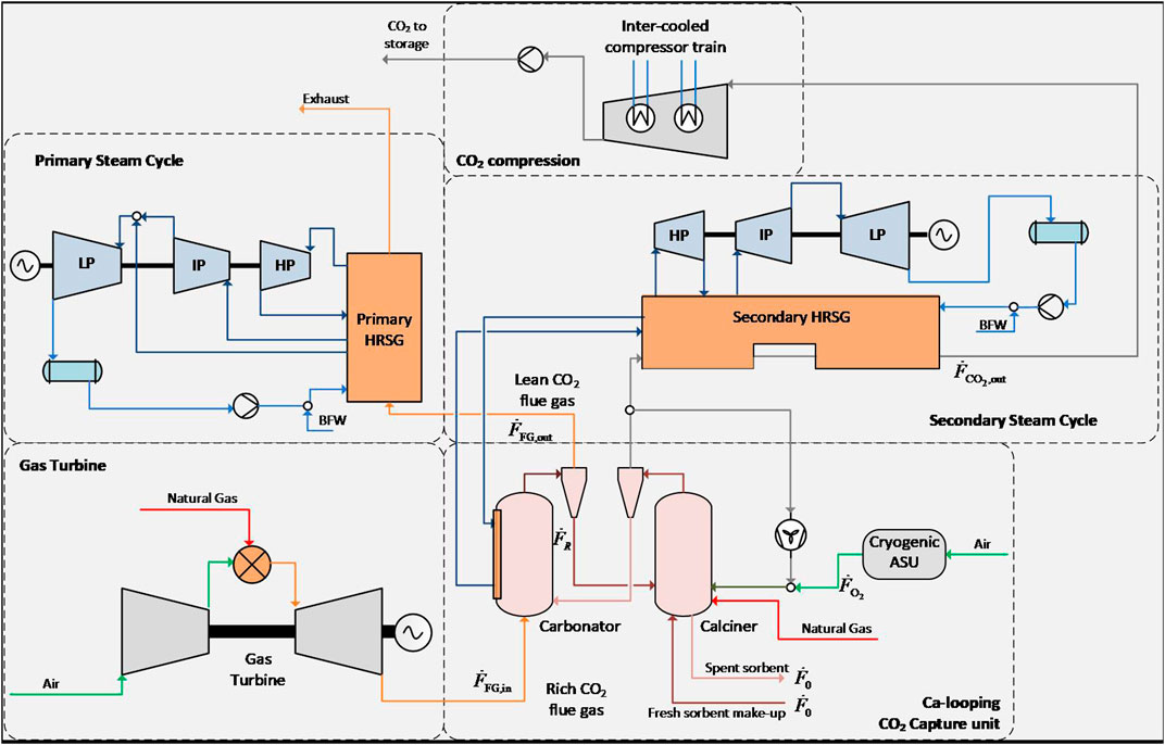
FIGURE 1. Process flow diagram of the overall NGCC plant with hot CO2 recycle for CaL capture (revised from Berstad et al. (2014)).
A more detailed description of the CaL CO2 capture unit is presented as following. The rich CO2 flue gas enters the carbonator where carbonation reactions take place. CO2 and CaO are converted into CaCO3. The CO2 lean flue gas passes through the carbonator cyclone where the carbonated particles are removed from the flue gas. The particles are sent to the calciner for regeneration (calcination). CaCO3 is decomposed into CO2 and CaO. The regenerated particles are removed from the CO2 stream by the calciner cyclone and sent back to the carbonator. The CO2 is sent for conditioning (compression and purification) after heat recovery. Heat is consumed in the calciner for calcination reactions and the heating of the feed streams (carbonated particles, fuels and the oxidant gases). In order to avoid dilute the CO2 stream, oxy-combustion of natural gas is used for heat supply to the calciner. A cryogenic air separation unit (ASU) is used for the O2 supply. A portion of the CO2 captured is recycled to the burner for temperature control. Note that the CO2 can be recycled either before or after partial heat recovery by the second HRSG. The former case (hot CO2 recycle) reduces the fuel supply to the calciner. However, it should be noted that the hot CO2 recycle is a considerable challenge in practice. Due to the degradation of sorbent particles, some solids are purged and substituted with fresh CaCO3 as make-up. A solid-solid heat exchanger has been used between the carbonated particles and regenerated particles for heat recovery in case 3A while not used in case 1A.
The key operating parameters and plant performance for the four cases are shown in Table 1. There are several differences between Cases 1A and 3A: 1) the sorbents are calcite and synthetic CaO respectively, 2) the calciner temperatures are 1,223.2 and 1,173.2 K respectively (see Table 2) 3) the solid-solid heat exchanger is not used in case 1A and is used in case 3A; 4) the recycled flue gas (CO2 captured) is cooled against the secondary HRSG system in case 1A before recycling and is not cooled in case 3A. Due to the secondary steam cycle, the NGCC with CaL capture generates more power than the NGCC without CO2 capture or with MEA capture, although they use the same gas turbine. The net power output is 547.0 MWe for case 1Aand 466.3 MWe for case 3A. Note that the gas turbine power is lower in the CaL capture cases (1A and 3A) since the exhaust pressure at the turbine outlet is assumed to be higher to properly account for the pressure losses in the CaL system. A pressure drop of 2 kPa was assumed in reference (Berstad et al., 2012) based on the results of a test rig of chemical looping combustion (CLC) at SINTEF Energy Research. The pressure drop calculation has not been included in details in this study. The pressure drop can be estimated using the solid inventory (unit area) multiplying by the gravity acceleration constant. According to the modeling results as shown in Table 2, a pressure drop of 20 kPa is assumed in this study. The turbine power as well as the primary gross steam cycle power are correspondingly updated. Also note that a removal efficiency of 90% is specified for the CO2 in the exhaust flue gas of the NGCC. However, a total capture rate of higher than 90% is achieved in the CaL capture cases since the CO2 is captured from the following three carbon sources: 1) the exhaust flue gas of the NGCC, 2) the fresh sorbent make-up, and 3) the oxy-combustion of fuels (natural gas) for heat supply to the calciner. Since the impurities in the CO2 captured are mainly introduced due to the oxy-combustion of fuels, the CO2 mole fraction in the CO2 captured are different in the two CaL capture cases due to different consumptions of fuels.
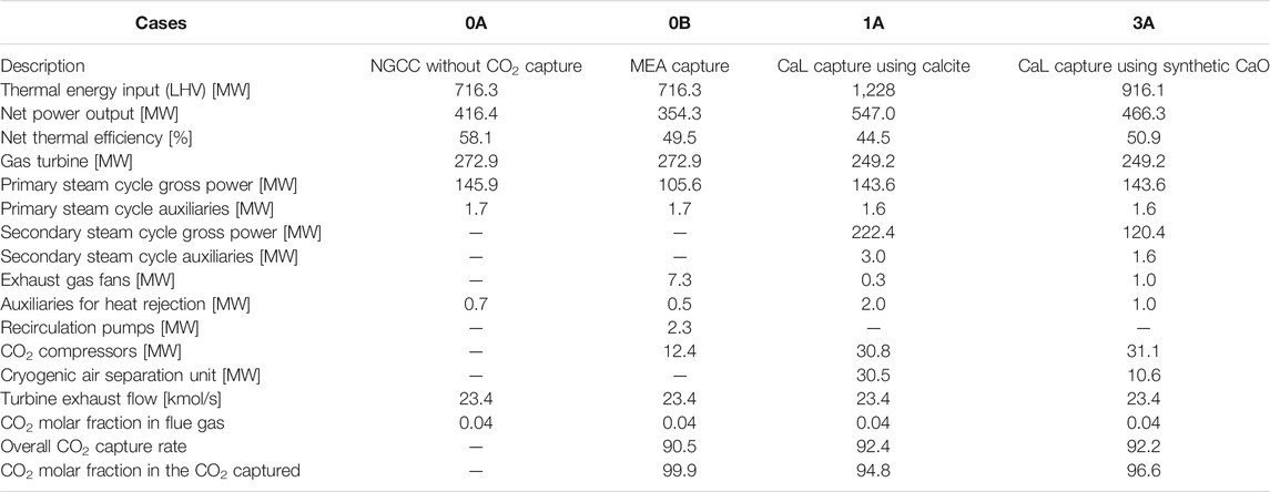
TABLE 1. Key parameters for the NGCC plants (Berstad et al., 2012; Berstad et al., 2014).
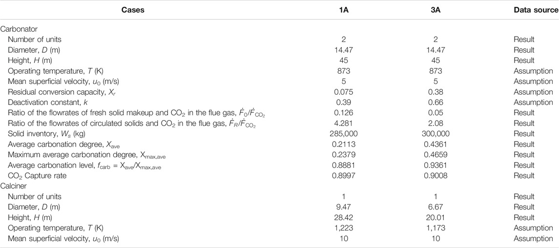
TABLE 2. Main design parameters for the carbonators and calciners.
Sizing Study
While most equipment of the CaL process can be sized using standard engineering approaches (cyclones, conveyor systems for solid particles, blower for the recycled flue gas and the air separation units, etc.), the sizing of the carbonator, calciner and solid-solid heat-exchanger is more challenging. Indeed, since CaL systems have never been implemented in industry, the sizing of non-standard equipment for industrial scale CaL systems is not straight forward. However, model based studies can still provide useful guidelines for preliminary sizing estimations.
Carbonator and Calciner Sizing
The carbonator model developed by Romano (2012) is here used for the sizing of carbonators in this work. This model is based on the Kunii-Levenspiel theory for circulating fluidized beds (Kunii and Levenspiel, 2000). Both reaction kinetics and solid flow distribution are considered in the model. The reactor has been divided into a bottom dense zone and an upper lean zone. The models are solved based on the carbon balance: the carbon removed from the gas phase equals to the carbon absorbed by the solid particles in the reactor. More details are referred to the work by Romano (2012) The assigned values for all the parameters are presented in Romano (2012) and are used in this study. The models are implemented with the numerical computation tool GNU Octave 4.0.0. (Eaton et al., 2015). The cross-section area and height of the carbonators can be determined using the model. Note that the carbonation reaction is exothermic and heat needs to be removed for steam generation as shown in Figure 1. It is assumed that 50% of the internal surface area (considering the installation) is covered by tubes for transferring the heat of carbonation reaction to the steam cycle. The number of units is specified as the minimum while the area is sufficient for heat transfer.
The sizing of the calciners is performed in a similar way. The calcination reaction is adiabatic and heat transfer area is not a concern for the calciners. The main design parameters of the carbonators and calciners in Cases 1A and 3A are presented in Table 2. Note that due to insufficient public sources for the design of carbonator/calciner particularly with large sizes, the two reactors (carbonator and calciner) are assumed to be circular types for the conceptual evaluation in this study. Similar assumptions have been used in other modeling studies (Romano, 2012; Ylätalo et al., 2014). The volumetric gas flow and thus the sizes of the calciner are smaller in case 3A for the following two reasons: 1) The amount of flue gas recycled is much smaller in case 3A due to the hot flue gas recycling, and 2) The operating temperature of the calciner is lower based on different assumptions.
Sizing of the Solid-Solid Heat Exchanger
According to Berstad et al. (2014), the energy penalty related to CO2 capture can be considerably reduced by using a solid-solid heat exchanger between the carbonated solids and the calcinated solids. The inclusion of the solid-solid heat exchanger in case 3A plays a significant part in the increase in efficiency of case 3A over case 1A. However, industrial applications of solid-solid heat exchangers are not common. Very little experience is available about the design of this type of heat exchangers. Vorrias et al. (2013) presented a configuration of concentric L-valves for the solid-solid heat exchange in the CaL process. The configuration is somewhat similar to the traditional shell-tube heat exchangers. Although the feasibilities of implementing this type of heat exchangers need further investigations, the L-valve exchanger is used for a conceptual design in this work for simplification. Calcination reaction may take place for some carbonated particles, however, the reaction is expected to have negligible influences on the overall energy balance. The calcination reaction is thus neglected in the heat exchanger. The minimum temperature difference for heat transfer is assumed to be 50 °C. The heat transfer coefficient on one side of the heat exchanger is assumed to be 400 W/(m2·K) according to a similar study on the heat transfer performance of solids in tubes (Flamant et al., 2013). The heat conduction between the particles on the same side of the heat exchanger is assumed to be fast due to good mixing of the solid particles with very small sizes. As a result, the heat transfer area for the solid-solid heat exchanger is calculated to be 2,818 m2 in case 3A.
Cost Analysis
In order to fully assess the potential of CaL, the costs of both CaL processes with their corresponding power plant are assessed and compared with the costs of a NGCC without capture and with MEA-based capture previously assessed by the European Benchmarking Task Force (EBTF) (Anantharaman et al., 2011).
Costing Methodology
A factored method is here used in order to assess the capital plant of the NGCC without and with CO2 capture (Roussanaly et al., 2013). Here the direct costs of the NGCC plant with and without MEA-based capture are scaled from Anantharaman et al. (2011). The direct costs of other processes are estimated, in Euro, with Aspen Process Economic AspenTech (2010) based on the equipment design. However, due to their specificity, the direct cost of the carbonator, calciner and solid-solid heat exchanger are assessed using the cost model proposed by the CEMCAP project (Cinti et al., 2018; Gardarsdottir et al., 2019; Voldsund et al., 2019) for these equipment. The investment cost of the NGCC plant with CO2 capture units is then calculated by multiplying the direct investment cost of equipment in the appropriate material by an indirect cost factor of 1.31 (Anantharaman et al., 2011).
The annual fixed operating costs are scaled based on the estimated labor cost and an annual maintenance and insurance cost equivalent to 4.5% of total direct costs. Meanwhile the annual variable operating costs are assessed based on the estimated utilities and material consumptions with the unit cost presented in Table 3. As the synthetic sorbent used in case 3A corresponds to a hypothetical material, its cost is, as a first approximation, assumed to be equal to that of conventional calcium oxide. However, the impact between sorbent performances and maximum acceptable sorbent cost will be explored in (Sorbent Performance).
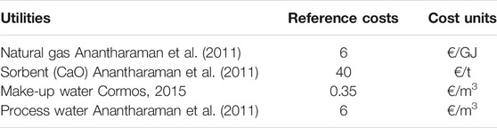
TABLE 3. Utilities cost.
The levelized cost of Electricity (LCOE) and CO2 avoided cost (CAC) as defined in reference (Roussanaly, 2019) are assessed and used as key performance indicators (KPIs) to compare the four cases. Both KPIs are calculated assuming a real discount rate of 8%, 7,400 annual operating hours and an economic lifetime of 25 years (Anantharaman et al., 2011). In addition, investment costs consider that construction is shared over a 3-years construction period (Anantharaman et al., 2011).
Cost Results
The results for the levelized cost of electricity (LCOE) and CO2 avoided cost (CAC) for the four cases considered are presented in Figure 2, while further details on the direct cost breakdown of the calcium looping cases is provided in Figure 3. The breakdown of CAPEX for the calcium looping configurations (1A and 3A) by section are presented in Table 4. The LCOEs of both the 1A and 3A concepts are respectively 86 and 83 €/MWh, while their corresponding CACs are equal to 95 and 86 €/tCO2,avoided. The calcium looping 1A and 3A processes are therefore respectively 21 and 17% more expensive than for the NGCC plant with MEA-based CO2 capture (71 €/MWh). As a consequence, the CAC in the cases 1A and 3A is significantly higher than for the MEA based capture (respectively 94 and 74% more expensive). These numbers clearly show that the CaL cases with the investigated process configurations are not economically competitive.
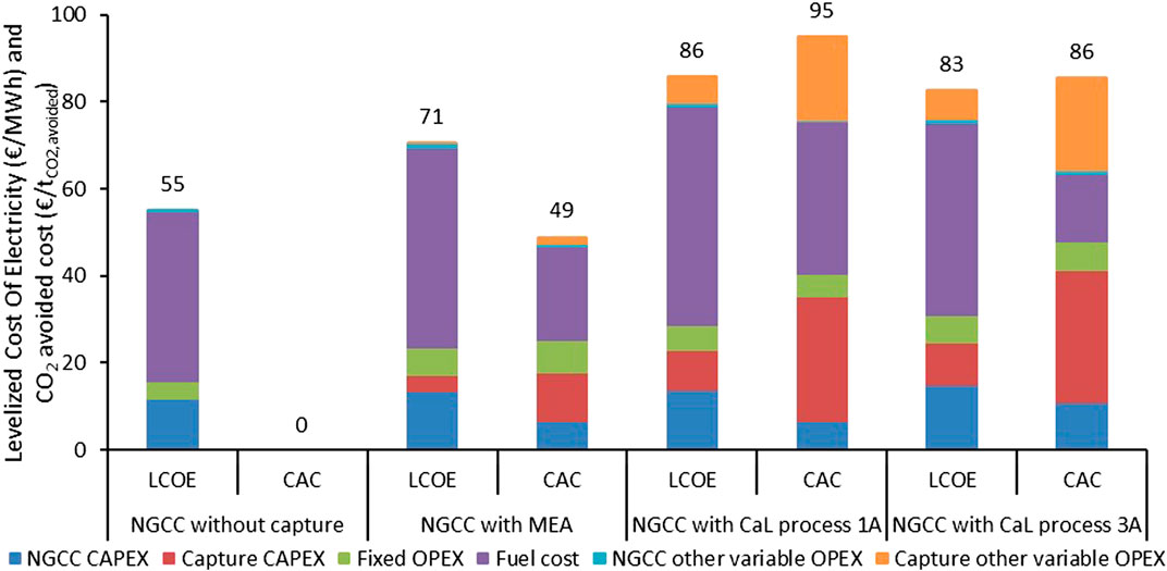
FIGURE 2. Levelized cost of electricity and CO2 avoided cost for the four NGCC cases considered.
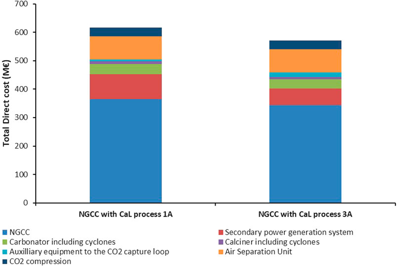
FIGURE 3. Breakdown of the total direct costs of the NGCC with calcium looping processes 1A and 3A.
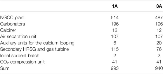
TABLE 4. Breakdown of CAPEX (M€) by section for the calcium looping configuration 1A and 3A.
To understand strong increases, it is important to look at the LCOE and CAC cost breakdowns. The CAC of the 1A process shows that the strongest contributor to the cost increase of the process is the loss in net electric efficiency of the plant (−3.9%-points compared to MEA), as well as the increased CO2 capture investment cost due to the complex process and large equipment (carbonator, calciners, ASU, etc). However, in the case 3A the cost increase is due to different factors. Indeed, while the high plant efficiency (+2.8 pt compared to MEA) limits the contribution of fuel to the CAC, the CO2 capture investment costs increases significantly, especially due to the large solid-solid heat exchanger. In both the 1A and 3A cases, the costs associated with sorbent make-up also play a significant role in the increase compared to the MEA-based case. Finally, it is worth noting that the CO2 avoided costs obtained here seems to be slightly higher than the one from Hu and Ahn (2017) (72 €/t). The difference between both studies may be explained by variation in energy penalty, sorbent make-up rate, gas cost, system boundaries considered in both studies.
It is worth noting that the plant net power output and the amount of CO2 captured varies between the three CO2 capture cases. Indeed, in the CaL processes, more power is produced by the oxy-combustion of natural gas in the calciner that generates more CO2 which must be captured in the process.
Finally, it should be noted that the CO2 purity after capture varies between the different cases. For the MEA capture process, the CO2 purity exceeds 99.9%, whereas it is 94.8% and 96.6% in cases 1A and 3A CaL processes. Although this is not included here, this may result in higher cost of transport or in additional purification steps for the CaL processes (Skaugen et al., 2016; Deng et al., 2019).
In order to understand how the LCOE and CAC for the CaL capture processes may be reduced in order to compete with MEA-based CO2 capture, sensitivity analyses are carried out on 10 key parameters and are presented in Figures 4, 5 (Van Der Spek et al., 2020). The parameter range variation considered are ±50%, except for the project duration which varies between 10 and 40 years, and the plant utilization rate which varies between 65 and 90%, and the plant thermal efficiency with the CaL process which varies by ± 5 pts. Indeed, a 5% pt increase in CO2 efficiency for case 3A is not thermodynamically possible, this would mean that the efficiency penalty for CO2 capture and compression would be 0.8% (which is lower than the thermodynamic minimum energy penalty). But this variation is included in order to provide an impression of whether the chasing further process improvements for the complex case 3A by adding further process components is relevant to investigate.
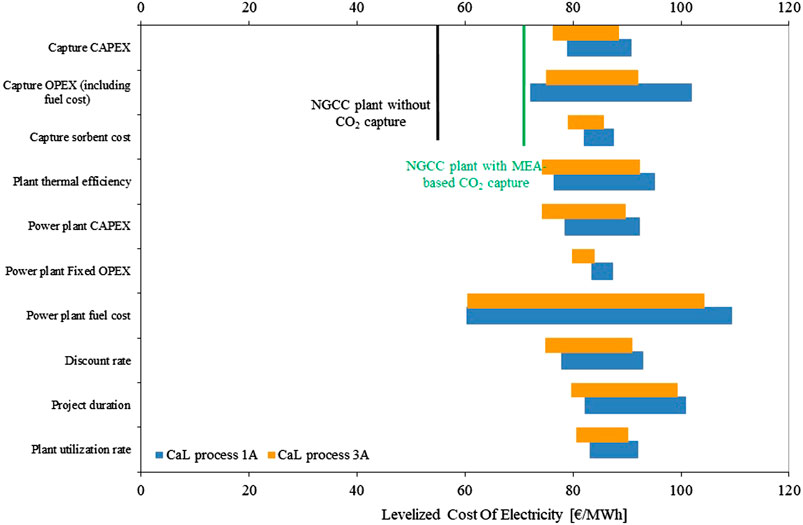
FIGURE 4. Sensitivity analyses on the LCOEs of the NGCC with the 1A and 3A CaL processes.
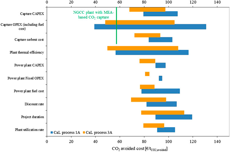
FIGURE 5. Sensitivity analyses on the CACs of the NGCC with the 1A and 3A CaL processes.
As expected from the large gaps in LCOEs and CACs, significant efforts would be required for the CaL process to become cost-competitive with MEA-based capture. The results show that improvement of a single parameter is far from enough to reach competitiveness of the CaL processes. Strong simultaneous improvements of the CO2 capture investment cost, the plant efficiency with CaL processes, and the annual sorbent cost would be required together in order to reach competitiveness in term of both LCOE and CAC. Furthermore, taking into account that the integration of CaL into the NGCC plant in practice would mean adding the carbonator between the gas turbine exhaust and the heat recovery steam generator, while the process integration for amine capture with the NGCC is much simpler, CaL capture from NGCC, with the investigated process configurations does not appear very attractive.
Although sensitivity on the power plant costs and project valuation (discount rate, project duration and utilization rate) for the NGCC with the two CaL processes are not compared with the NGCC plant without or with MEA-based capture, it is worth noting that they follow the same trends (Anantharaman et al., 2011).
Sorbent Performance
As shown by the sensitivity analyses, exploring more advanced sorbent is a critically parameter to reduce the cost of the CaL processes. Thus, the impact of two critical sorbent characteristics are considered: 1) the potential gain in overall plant efficiency, and 2) the annual make-up rate. The impact on these two parameters on the advanced sorbent cost, which results in the same electricity cost as in the base 1A and 3A. This advanced sorbent cost, plotted in Figure 6, represent the maximum advanced sorbent cost acceptable in order to make a CaL process cheaper than in the base cases.
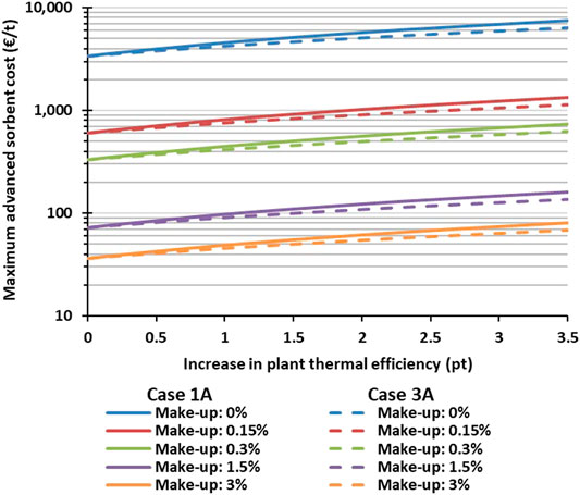
FIGURE 6. The maximum unitary cost of a sorbent to compete with the CaL processes in this study.
The evaluation illustrates that advanced sorbent which could increase the plant efficiency and reduce sorbent make-up have a significant value. Indeed, the maximum advanced sorbent cost increases by a factor up to 200 for the ranges considered. The strongest impacts appear to be due to the reduction in the sorbent make-up rate, which emphasizes the potential of stable sorbent for the CaL processes, while improvements in the energy performance also play an important role. Although these evaluations assumed that the remaining part of the CaL process remains identical to the base cases, the evaluation presented in Figure 6 could be used to perform a material screening and identify advanced sorbent which could result in improved performance for the CaL processes.
Conclusion
The paper has presented a techno-economic study on two CaL processes for CO2 capture from a NGCC. The sizing of non-conventional equipment such as the carbonator, calciner and the solid-solid heat exchanger has been introduced in details. The modeling and sizing results have been used as the basis for cost analyses for the non-conventional equipment. A reference MEA capture process and a NGCC without CO2 capture have been included for the comparison basis. While the cost of NGCCs is performed using a scaling approach, the direct cost of other processes are estimated with Aspen Process Economic Analyzer. The key finding from the cost analyses is that the CaL system presented in this study does not appear to be cost competitive with the MEA capture process. The CO2 avoided cost is 95 and 86 €/tCO2,avoided for the two CaL cases respectively. The values are considerably higher than the cost of MEA capture, which is 49 €/tCO2,avoided. The largest contribution to the CO2 avoided cost is the capture CAPEX. The combination of the primary and secondary steam cycles into one could possibly reduce the NGCC CAPEX. Nevertheless, the hot gas recycling, the solid-solid heat exchanger, and the integration of the carbonator process between the gas turbine exhaust and the heat recovery steam generator remain practical challenges.
Data Availability Statement
The original contributions presented in the study are included in the article/Supplementary Material, further inquiries can be directed to the corresponding author.
Author Contributions
FC and SR wrote the first version of the manuscript. RA and KJ contributed to conceptualization, analysis and review.
Funding
This publication has been produced with support from the BIGCCS Center, performed under the Norwegian research program Centers for Environment-friendly Energy Research (FME). The authors acknowledge the following partners for their contributions: Gassco, Shell, Statoil, TOTAL, Engie and the Research Council of Norway (193816/S60). This publication has been produced with support from the NCCS Center, performed under the Norwegian research program Centers for Environment-friendly Energy Research (FME). The authors acknowledge the following partners for their contributions: Aker Solutions, Ansaldo Energia, CoorsTek Membrane Sciences, EMGS, Equinor, Gassco, Krohne, Larvik Shipping, Lundin, Norcem, Norwegian Oil and Gas, Quad Geometrics, Total, Vår Energi, and the Research Council of Norway (257579/E20).
Conflict of Interest
The authors declare that the research was conducted in the absence of any commercial or financial relationships that could be construed as a potential conflict of interest.
Acknowledgments
The authors acknowledge Karl Lindqvist at SINTEF Energy Research for his preliminary sizing work about the cyclones and calciners in the CaL system.
References
Alonso, M., Rodríguez, N., Grasa, G., and Abanades, J. C. (2009). Modelling of a fluidized bed carbonator reactor to capture CO2 from a combustion flue gas. Chem. Eng. Sci. 64, 883–891. doi:10.1016/j.ces.2008.10.044
Anantharaman, R., Bolland, O., Booth, N., Van Dorst, E., Ekstrom, C., Sanchez Fernandez, E., et al. (2011). European best practice guidelines for assessment of CO2 capture technologies. in Public deliverable D1. (London, United Kingdom: Alstom), 4.
Arias, B., Diego, M. E., Abanades, J. C., Lorenzo, M., Diaz, L., Martínez, D., et al. (2013). Demonstration of steady state CO2 capture in a 1.7 MWth calcium looping pilot. Int. J. Greenh. Gas Control. 18, 237–245. doi:10.1016/j.ijggc.2013.07.014
Berstad, D., Anantharaman, R., Blom, R., Jordal, K., and Arstad, B. (2014). NGCC post-combustion CO2 capture with Ca/carbonate looping: efficiency dependency on sorbent properties, capture unit performance and process configuration. Int. J. Greenh. Gas Control. 24, 43–53. doi:10.1016/j.ijggc.2014.02.015
Berstad, D., Anantharaman, R., and Jordal, K. (2012). Post-combustion CO2 capture from a natural gas combined cycle by CaO/CaCO3 looping. Int. J. Greenh. Gas Control. 11, 25–33. doi:10.1016/j.ijggc.2012.07.021
Cinti, G., Anantharaman, R., De Lena, E., Fu, C., Gardarsdottir, S. O., Hoppe, H., et al. (2018). CEMCAP, D4.4 Cost of critical components in CO2 capture processes. Available at: https://www.sintef.no/globalassets/project/cemcap/2018-11-14-deliverables/d4.4-cost-of-critical-components-in-co2-capture-processes.pdf. (Accessed November 12, 2020)
Coppola, A., and Scala, F. (2020). A preliminary techno-economic analysis on the calcium looping process with simultaneous capture of CO2 and SO2 from a coal-based combustion power plant. Energies 13, 2176. doi:10.3390/en13092176
Cormos, C.-C. (2015). Assessment of chemical absorption/adsorption for post-combustion CO2 capture from Natural Gas Combined Cycle (NGCC) power plants. Appl. Therm. Eng. 82, 120–128. doi:10.1016/j.applthermaleng.2015.02.054
De Lena, E., Spinelli, M., Gatti, M., Scaccabarozzi, R., Campanari, S., Consonni, S., et al. (2019). Techno-economic analysis of calcium looping processes for low CO2 emission cement plants. Int. J. Greenh. Gas Control. 82, 244–260. doi:10.1016/j.ijggc.2019.01.005
Deng, H., Roussanaly, S., and Skaugen, G. (2019). Techno-economic analyses of CO2 liquefaction: impact of product pressure and impurities. Int. J. Refrig. 103, 301–315. doi:10.1016/j.ijrefrig.2019.04.011
Dieter, H., Bidwe, A. R., Varela-Duelli, G., Charitos, A., Hawthorne, C., and Scheffknecht, G. (2014). Development of the calcium looping CO2 capture technology from lab to pilot scale at IFK. Fuel., 127, 23–37. doi:10.1016/j.fuel.2014.01.063
Eaton, J. W., Bateman, D., Hauberg, S., and Wehbring, R. (2015). GNU Octave version 4.0.0 manual: a high-level interactive language for numerical computations. Available at: https://www.gnu.org/software/octave/doc/interpreter/. (Accessed November 12, 2020)
Eran, M., Hanak, D., Mir, J., Anthony, E. J., and Manovic, V. (2016). Process modelling and techno-economic analysis of natural gas combined cycle integrated with calcium looping. Therm. Sci. 20, S59–S67. doi:10.2298/TSC1151001209E
Fang, F., Li, Z.-S., and Cai, N.-S. (2009). Experiment and modeling of CO2 capture from flue gases at high temperature in a fluidized bed reactor with Ca-based sorbents. Energy & Fuels 23, 207–216. doi:10.1021/ef800474n
Figueroa, J. D., Fout, T., Plasynski, S., Mcilvried, H., and Srivastava, R. D. (2008). Advances in CO2 capture technology-the U.S. Department of energy's carbon sequestration program. Int. J. Greenh. Gas Control. 2, 9–20. doi:10.1016/S1750-5836(07)00094-1
Flamant, G., Gauthier, D., Benoit, H., Sans, J.-L., Garcia, R., Boissière, B., et al. (2013). Dense suspension of solid particles as a new heat transfer fluid for concentrated solar thermal plants: on-sun proof of concept. Chem. Eng. Sci. 102, 567–576. doi:10.1016/j.ces.2013.08.051
Gardarsdottir, S. O., De Lena, E., Romano, M., Roussanaly, S., Voldsund, M., Pérez-Calvo, J.-F., et al. (2019). Comparison of technologies for CO2 capture from cement production—Part 2: cost analysis. Energies 12, 542. doi:10.3390/en12030542
Global CCS Institute (2016). Global status of CCS: 2016 summary report, Availabale at: https://www.globalccsinstitute.com/archive/hub/publications/201158/global-status-ccs-2016-summary-report.pdf. (Accessed November 12, 2020)
Grasa, G., Abanades, J., Alonso, M., and Gonzalez, B. (2008). Reactivity of highly cycled particles of CaO in a carbonation/calcination loop. Chem. Eng. J. 137, 561–567. doi:10.1016/j.cej.2007.05.017
Hanak, D. P., Anthony, E. J., and Manovic, V. (2015). A review of developments in pilot-plant testing and modelling of calcium looping process for CO2 capture from power generation systems. Energy Environ. Sci. 8, 2199–2249. doi:10.1039/C5EE01228G
Hu, Y., and Ahn, H. (2017). Techno-economic analysis of a natural gas combined cycle power plant integrated with a Ca-looping process for post-combustion capture. Energy Procedia 105, 4555–4560. doi:10.1016/j.egypro.2017.03.978
Kremer, J., Galloy, A., Ströhle, J., and Epple, B. (2013). Continuous CO2 capture in a 1-MW th carbonate looping pilot plant. Chem. Eng. Technol. 36, 1518–1524. doi:10.1002/ceat.201300084
Kunii, D., and Levenspiel, O. (2000). The K-L reactor model for circulating fluidized beds. Chem. Eng. Sci. 55, 4563–4570. doi:10.1016/S0009-2509(00)00073-7
Martínez, I., Grasa, G., Murillo, R., Arias, B., and Abanades, J. C. (2012). Kinetics of calcination of partially carbonated particles in a Ca-looping system for CO2 capture. Energy & Fuels 26, 1432–1440. doi:10.1021/ef201525k
Martínez, I., Grasa, G., Murillo, R., Arias, B., and Abanades, J. C. (2013). Modelling the continuous calcination of CaCO3 in a Ca-looping system. Chem. Eng. J. 215-216, 174–181. doi:10.1016/j.cej.2012.09.134
Martínez, I., Grasa, G., Parkkinen, J., Tynjälä, T., Hyppänen, T., Murillo, R., et al. (2016). Review and research needs of Ca-Looping systems modelling for post-combustion CO2 capture applications. Int. J. Greenh. Gas Control. 50, 271–304. doi:10.1016/j.ijggc.2016.04.002
Martínez, I., Murillo, R., Grasa, G., and Carlos Abanades, J. (2011). Integration of a Ca looping system for CO2 capture in existing power plants. AIChE J. 57, 2599–2607. doi:10.1016/j.egypro.2011.02.043
Michalski, S., Hanak, D. P., and Manovic, V. (2019). Techno-economic feasibility assessment of calcium looping combustion using commercial technology appraisal tools. J. Clean. Prod. 219, 540–551. doi:10.1016/j.jclepro.2019.02.049
Perejón, A., Romeo, L. M., Lara, Y., Lisbona, P., Martínez, A., and Valverde, J. M. (2016). The Calcium-Looping technology for CO2 capture: on the important roles of energy integration and sorbent behavior. Appl. Energy 162, 787–807. doi:10.1016/j.apenergy.2015.10.121
Rodríguez, N., Alonso, M., and Abanades, J. C. (2010). Average activity of CaO particles in a calcium looping system. Chem. Eng. J. 156, 388–394. doi:10.1016/j.cej.2009.10.055
Romano, M. C. (2012). Modeling the carbonator of a Ca-looping process for CO2 capture from power plant flue gas. Chem. Eng. Sci. 69, 257–269. doi:10.1016/j.ces.2011.10.041
Roussanaly, S., Brunsvold, A. L., Hognes, E. S., Jakobsen, J. P., and Zhang, X. (2013). Integrated techno-economic and environmental assessment of an amine-based capture. Energy Procedia 37, 2453–2461. doi:10.1016/j.egypro.2013.06.126
Roussanaly, S. (2019). Calculating CO2 avoidance costs of carbon capture and storage from industry. Carbon Manag. 10, 105–112. doi:10.1080/17583004.2018.1553435
Skaugen, G., Roussanaly, S., Jakobsen, J., and Brunsvold, A. (2016). Techno-economic evaluation of the effects of impurities on conditioning and transport of CO2 by pipeline. Int. J. Greenh. Gas Control. 54, 627–639. doi:10.1016/j.ijggc.2016.07.025
Van Der Spek, M., Fout, T., Garcia, M., Kuncheekanna, V. N., Matuszewski, M., Mccoy, S., et al. (2020). Uncertainty analysis in the techno-economic assessment of CO2 capture and storage technologies. Critical review and guidelines for use. Int. J. Greenh. Gas Control. 100, 103113. doi:10.1016/j.ijggc.2020.103113
Voldsund, M., Gardarsdottir, S. O., De Lena, E., Pérez-Calvo, J.-F., Jamali, A., Berstad, D., et al. (2019). Comparison of technologies for CO2 capture from cement production—Part 1: technical evaluation. Energies 12, 559. doi:10.3390/en12030559
Vorrias, I., Atsonios, K., Nikolopoulos, A., Nikolopoulos, N., Grammelis, P., and Kakaras, E. (2013). Calcium looping for CO2 capture from a lignite fired power plant. Fuel 113, 826–836. doi:10.1016/j.fuel.2012.12.087
Yang, Y., Zhai, R., Duan, L., Kavosh, M., Patchigolla, K., and Oakey, J. (2010). Integration and evaluation of a power plant with a CaO-based CO2 capture system. Int. J. Greenh. Gas Control. 4, 603–612. doi:10.1016/j.ijggc.2010.01.004
Ylätalo, J., Ritvanen, J., Arias, B., Tynjälä, T., and Hyppänen, T. (2012). 1-Dimensional modelling and simulation of the calcium looping process. Int. J. Greenh. Gas Control. 9, 130–135. doi:10.1016/j.ijggc.2012.03.008
Keywords: calcium looping, CO2 capture, sizing, techno-economic analysis, natural gas combined cycles
Citation: Fu C, Roussanaly S, Jordal K and Anantharaman R (2021) Techno-Economic Analyses of the CaO/CaCO3 Post-Combustion CO2 Capture From NGCC Power Plants. Front. Chem. Eng. 2:596417. doi: 10.3389/fceng.2020.596417
Received: 19 August 2020; Accepted: 01 December 2020;
Published: 11 January 2021.
Edited by:
Gyorgy Szekely, King Abdullah University of Science and Technology, Saudi ArabiaReviewed by:
Mani Sarathy, KAUST, Clean Combustion Research Center, Thuwal, Saudi ArabiaEdward Anthony, University of Ottawa, Canada
Copyright © 2021 Fu, Roussanaly, Jordal and Anantharaman. This is an open-access article distributed under the terms of the Creative Commons Attribution License (CC BY). The use, distribution or reproduction in other forums is permitted, provided the original author(s) and the copyright owner(s) are credited and that the original publication in this journal is cited, in accordance with accepted academic practice. No use, distribution or reproduction is permitted which does not comply with these terms.
*Correspondence: Chao Fu, chao.fu@sintef.no