Pole-Changing Windings for Close Ratio and 1:N Ratio Using the 3//Y / 3//Y Method
Pole-Changing Windings for Close Ratio and 1:N Ratio Using the 3//Y / 3//Y Method
Volume 3, Issue 4, Page No 241-253, 2018
Author’s Name: Gabor Kovacsa)
View Affiliations
Ganz Electric Works, 1095 Budapest, Soroksari ut. 30-34. Hungary
a)Author to whom correspondence should be addressed. E-mail: gabor.kovacs.ganz@gmail.com
Adv. Sci. Technol. Eng. Syst. J. 3(4), 241-253 (2018); ![]() DOI: 10.25046/aj030424
DOI: 10.25046/aj030424
Keywords: Induction motor, Pole changing 3Y / 3Y method, Pole changing 1:N

Export Citations
Requirement for pole-changing motors emerged at the very early times of asynchronous motor design. Different solutions have been elaborated and some of them are generally used. One of these solutions in use is the so called pole phase modulation method. The so called 3 Y / 3 Y pole-changing winding being subject of this paper belongs to this group. This paper presents a new approach to this method. A new, complete and comprehensive study is introduced, including features and, moreover, detailed design guidelines. The method is applicable for any pole combination for the so called close ratio without any further particular consideration. As the target of the paper is to provide solution for high power application, it does not deal with balancing methods, but as a novelty, calculates the effect of those disadvantageous phenomena (asymmetries, even harmonics) in order to enable the designer for evaluation and decision. The study also reveals as a novelty that the same method is suitable for wide ratio as well, moreover, a new solution for theoretically infinite ratio expressed in 1:N, with supply voltage system of N phase is proposed. Using this motor, a new and complete drive system has been proposed with subject pole changing motor as core element as the most appropriate arrangement of high power main marine propulsion drive.
Received: 29 June 2018, Accepted: 31 July 2018, Published Online: 05 August 2018
1. Introduction
This paper is an extension of work originally presented at the International Conference on Electrical Machines 2018. organized by the World Academy of Science, Engineering and Technology [1].
The original work is extended in terms of
- much wider references are presented and deeply analyzed
- in case of close ratio,
- the effect of the unavoidable even harmonics are not only generally analyzed but calculation methods are given as well; the limits for omitting balancing measures are clearly given and are supported by calculations
- calculation methods are given to support the work of a designer of such motor (such as: winding pitch, maximum fundamental torques, air gap induction, harmonic torques, current imbalance).
- in case of wide ratio,
- the necessity of NxN-times phase supply on the lower pole number is clearly explained by voltage vector diagram; winding pattern also for 1:5 is given demonstrating how to create the winding of any ratio for 1:N by applying N-phase supply system and N//Y / N//Y connection
- supply strategies are given supported by calculation.
2. Pole changing motors
The objective of motor designers for industrial use was, from the beginning, to provide two speeds in a single motor instead of one speed only.
There are two main methods for pole changing of motors which are most generally used. The first method creates two independent windings in the stator, which is basically two motors in one: both windings can be ideally designed for their respective speeds in the meaning that the number of turns per slot may be chosen freely corresponding to the number of the pole. Due to the fact, however, that only one of the windings works at a time, the size of such motors is much bigger than the size of a corresponding single speed motor. The method is generally used for close ratio, practically any pole combination can be implemented [2].
The second method is based on changing the connection of parts of a winding called pole amplitude modulation (PAM motor): a part of the winding is connected in a to-and-back direction in order to achieve the basic and then the modulated pole number. Although the entire winding is working on both speeds at any given moment, two inherent disadvantages cannot be avoided: a number of additional terminals are required, therefore the drive must be fitted with a specially designed switching apparatus, and the magnetic field/wave in the airgap is always considerably distorted on the modulated speed. With this method, the possible pole combinations are limited. The method is used both for close ratio as well as for wide ratio.
Another group of methods is the one so called pole phase modulation. With this method, subdivided parts of the winding belong to one phase for one pole number while some of them will be moved to another phase for forming the other pole number. Intensive research has been performed on this field so far. Although the method is suitable for both close and wide ratio, the research is more focusing on the wide ratio nowadays.
Serious proposals for wide ratio might have started with the pioneer works of [3] and [4] both research groups working parallel to each other, reaching almost the same result, proposing 1:3 ratio pole changing winding with ideal (inherently balanced) characteristics. They admit, however, “it is not suggested that this phenomenon is likely to have any application but is of interest as an instructional demonstration”. [5] gives design criteria for pole changing motors as a summarizing work of the results till that time. 3 parallel connection was proposed at an early time by that milestone work of [6], with advantageous 6 terminals only. Its strategy is, however, completely different from that given in present paper. Yet, it was expressly stated by them that the method is suitable for close ratio only. Further, each pole combination required special considerations to implement, sometimes with coil omission; and for low power only. Current imbalance between parallel branches was just mentioned, but not discussed, not explained, even not calculated. [7] states to have developed a computer program for any pole combination of close as well as wide ratio prevailing on the previous results of the technique. 1:4, even 1:7 ratio machines were tested but at laboratory size only. [8] gives again a special solution for 1:4 ratio, again for low power. In [9], a 1:3 pole ratio motor was developed for a 9-phase supply on the lower pole number. Moreover, they studied and solved the smooth transition from one pole to the other by the control of the inverter supply, marking out a direction for future research for others. [10] and [11] were dealing with the same motor. The connection for a pole number to the other and for a phase number to the other are not made within the motor but by the control of the 9-phase supply. Therefore, the solution is rather a pole changing system than a pole changing winding. [12] is again a paper with summarizing value by giving general winding design rule for the pole phase modulation. Control algorithms were also developed. [13] and others not listed here are strongly working on eliminating imbalance of the winding for close ratio, proposing successful balancing methods.
These methods, however, although being suitable for low power but cannot be applied for high power motors (e.g. different turn numbers per slot). [14] is one example for the seemingly recent direction of research where as many as 5 different pole numbers are integrated in one motor. The solution is again such that the connection (and the pole changing at all) is not made within the motor but by the control of the supply (each slot being controlled by its own inverter).
Generally, it can be stated that the works are related to low power, laboratory size and they propose particular solution only. Some solutions are proposed for close ratio only while the rest only for wide ratio, respectively. Also the help of the supply is required in many cases for implementing the pole changing effect.
Approach of each paper (and of those not listed here) is different from that presented in this paper; work presented in [15] and [16] was not taken by anybody into consideration.
3. 3//Y / 3//Y Method
Belonging to the family pole-phase-modulation, another alternative is the so-called 3//Y/3//Y method. It is a real pole changing winding. Advantages of this solution are that the entire winding is working at any given moment and only 6 terminals are needed. At the same time, however, certain characteristics may be unfavorable. There may be certain asymmetries and additional even harmonics values. Therefore, calculation methods shall be given for those undesirable phenomena, in order to evaluate their importance.
As the 3// connection is inherently suitable for high power and balancing measures proposed by others are hardly feasible on that field, this paper will not deal with them. Instead, calculation methods will be introduced in order to enable the designer to evaluate those unfavorable phenomena.
It will be shown that both close ratio as well as wide ratio pole changing winding can be implemented by this single method.
4. Basic Idea behind the 3//Y/3//Y Method
Figure 1 (see [15] and [16]) shows a pole-changing connection for 4/6 pole. Instead of the usual 60° phase belt, such connections are prepared with a 120° phase belt and two-layer winding. Figure 1 (a) and (b) shows the upper layer for 4-pole and 6-pole connections, respectively. Figure 1 (c) shows the necessary subdivision into parts being smaller than q slot (slot number per phase per pole) on 4 pole.
The figure indicates the relationship between those subdivided parts of the winding and phases, indicating a 4-pole connection in one case (d) and a 6-pole connection in the other (e). It is clear that certain winding parts belong to a certain phase for 4-pole and to another phase for 6-pole.
In subject case, winding group 1, 4, 7 remains in the same phase; however, all the rest is moved to another phase. Because the groups are connected into series, 15 terminals and an appropriate switch are required.
It is clear that the elements of groups 2, 5, 8 as well as 3, 6, 9 shall be identical among each other; otherwise they could not be interchanged with each other.
Considering those three groups as a whole, it becomes clear that group 1, 4, 7, group 2, 5, 8 and group 3, 6, 9 are also identical with each other allowing them to be connected in parallel.
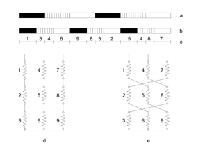 Figure 1. Classical pole changing winding according to [15] and [16]
(a) upper layer for 4-pole connection
(b) upper layer for 6-pole connection
(c) subdivision of the winding
(d) connection of winding for 4-pole
(e) connection of winding for 6-pole
This consideration opens a new way for a much simpler solution.
See connection pattern on Figure 2.
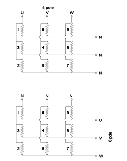 Figure 2. Pole changing winding by 3//Y / 3//Y method
5. Application of the method for close ratio
5.1. Phase Imbalance between Groups to be connected in Parallel
Such question does not arise for the original series connection, as just because of the series connection, the system is inherently balanced. The same is not evident, however, for the parallel connection. Therefore, Figure 1. and Figure 2. shall be considered again showing the origin and the derivation of the method.
The method of derivation for the 6-pole connection will be analyzed first. It is clear that always full poles are connected into the final scheme (no further subdivision for these) and these full poles are obviously always in the right phase angles. Therefore the 6-pole connection is always and inherently balanced.
In another case when 6 pole is the lower pole number, its full poles are, however, necessarily subdivided. Yet these subdivided parts (taken from different poles) are in the end always connected into series in a way as to always create full poles again see and consider Figure 5a. Generally, it stands that if the pole number is an integer multiplier of 6, it is always balanced, regardless of whether it is the higher or the lower pole number.
Returning to the derived 4-pole connection and in order to make the explanation more transparent, some of the already subdivided parts “are further cut” in order to better illustrate the phase angle of the voltage induced in them see Figure 3a. Then, in Figure 3b. the resulting induced voltage pattern are provided for each 3-phase group to be connected into parallel.
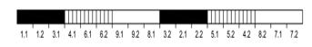 Figure 3a. Sketch for 4-pole connection serving as reference for Figure 1a.
The voltage values of the 3 groups to be connected in parallel are not balanced. It is clear that the vector difference between the supply and the induced voltage of each group (being always 20°) will drive equalizing currents in each group. In order to extend the picture the same pattern is provided for 8 pole as well. Figure 4. indicates the final result only.
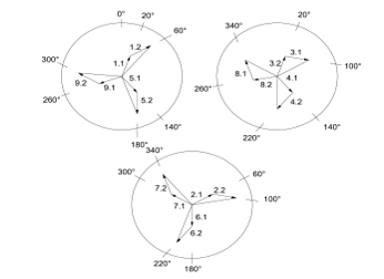 Figure 3b. Voltage vector pattern for 4-pole connection
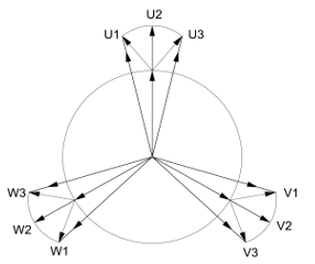 Figure 4. Voltage vector pattern for 8 pole connection acc. to Winding Scheme on Figure 5b.
As seen the imbalance is less. The reason for this is that, in case of 4 poles, all poles are subdivided into 3 parts that results necessarily in no right phase angle. At 8 poles, however, regardless of whether it is the higher or the lower pole number, the “first 6 poles” are always being put together creating full poles (and symbolized by those 3 vectors in the circle being 120° from each other), and only the “last 2 poles” are subdivided in an undesirable way (symbolized by those 3 vectors starting from those previous ones, always 40° from each other). Therefore, the 8 pole connection contains definitely fewer imbalances. The same consideration applies for higher pole numbers. Both Figure 3b and Figure 4 show the vectors in a true scale.
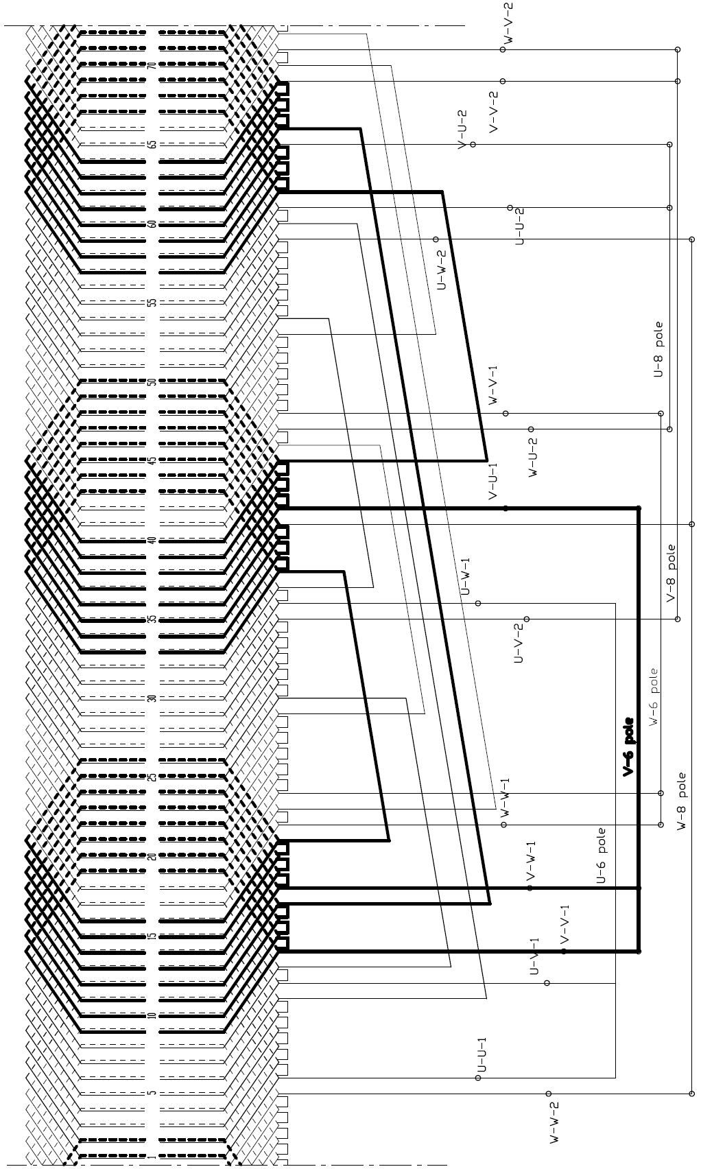 Figure 5a. Winding Scheme when supplied on the terminals marked by 6 pole
The induced voltages as well as (obviously) the supply voltage of each group constitute a symmetrical 3-phase system. It is the vector difference between them which drives the equalizing currents. Therefore no negative sequence currents will arise. The equalizing current will be appr. perpendicular to the magnetizing current in group 1 and group 3, while it will be parallel and in the sense against the magnetizing current in group 2. Then, the superposition method shall be used for the resulting current (and resulting air-gap induction) in each group. Local irregularities (copper losses, air gap & iron core induction) arise in this way. A short approximate calculation method will be given for the equalizing currents in the Appendix.
5.2. Actual implementation
An actual implementation by showing both layers of the winding is presented on Figure 5. as an example and demonstration. It shows how the winding of a real motor looks like in the high power industry, not in a laboratory. From now on a 6/8-pole winding will be taken as an example for further considerations.
Figure 5a shows the result supplied at the terminals marked for 6-pole, while Figure 5b shows the result supplied at the terminals marked for 8-pole.
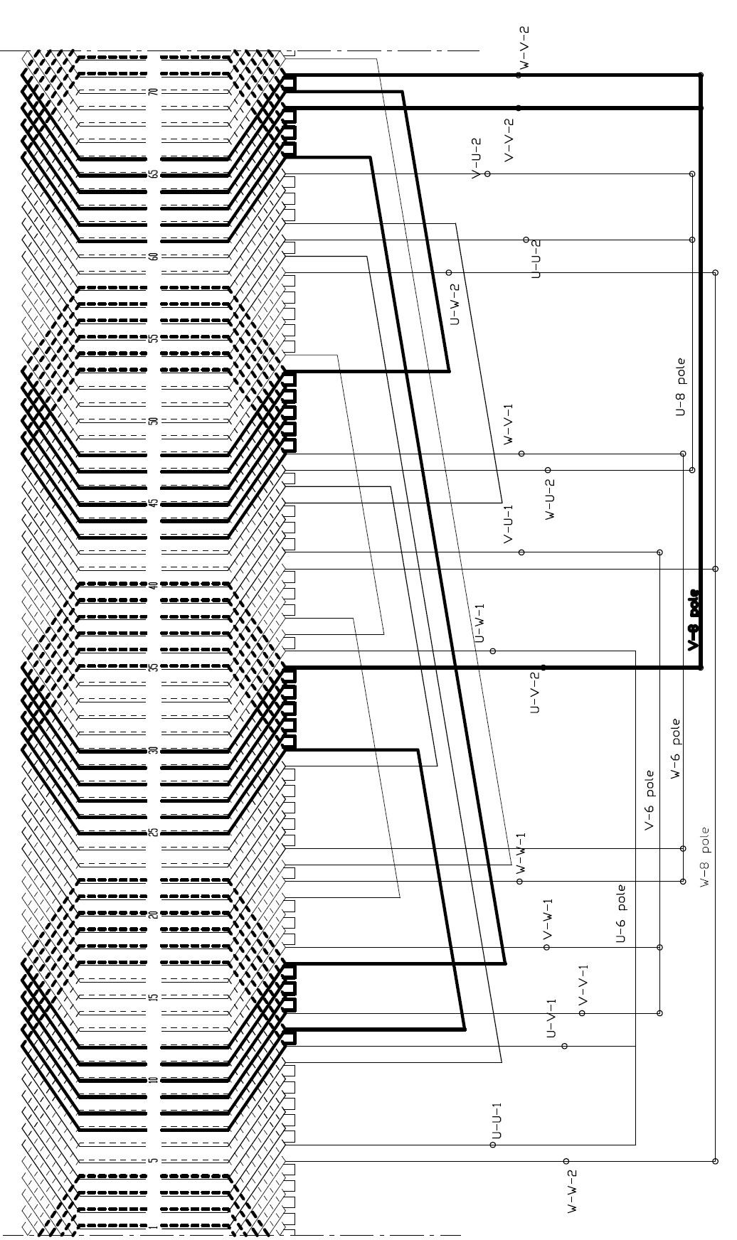 Figure 5b. Winding Scheme when supplied on the terminals marked by 8 pole
There are three terminals for both pole numbers: one group is used for power supply for 6-pole, whereas the other three terminals are used as the star points, therefore these latter remain idle. The opposite is true for 8-pole: the other group of three terminals, used earlier as star points, is used now for power supply, whereas the former group remains idle as star points. Those terminals, serving actually for star-points, do not need to be short-circuited.
The basic connection scheme in [15] and [16] see Figure 1. implies the concept of subdivision of the winding (=of the poles) and then the re-grouping as well. It is presented there as a particular solution, only for 4/6 poles. By understanding the concept, however, a winding for any pole combination can be created with no limitation. Endwinding connections are “longer” than those of usual single speed motors but note that each of them shall be dimensioned on the 1/3 of rated current only.
5.3. Design Aspects
5.3.1. Stator slot number
The possible stator slot numbers are considered for this method now. Because the slots are subdivided into nine groups, the slot numbers must be integer multiple of 9, no matter which are the pole combinations.
The best is to apply the rule for slot numbers in case of two independent windings [2]. Three-phase motor slot numbers are always integer multiple of 3. Slot numbers possible generally for pole changing motors with two independent windings are integer multiple of a further coefficient of 3 if any of the pole numbers is integer multiple of 6, so the slot numbers suitable for pole changing winding will be inherently integer multiple of 9 in such cases. For the rest of combinations like 8 – 10, 10 – 14, 14 – 16, etc., that above resulting slot number must be multiplied by 3.
5.3.2. Rotor slot number
The subject method does not imply any new requirement regarding rotor slot number, therefore traditional considerations may be applied. Yet, because of the even harmonics, in order to reduce the magnitude of their counteraction with other fields, rotor slot numbers higher than that of the stator may be recommended.
5.3.3. Winding pitch
The main (or perhaps the only) tool for the designer having in hand: the winding pitch. This fact has gained little consideration so far, it is for this 120° phase belt, however, of basic importance. Again, see Figure 5a for the lower pole number and then Figure 5b for the higher pole number.
In case if the pitch would be 1 – 13, this would mean full pitch for 6 pole, the arrangement is symmetrical, that is no even harmonic, the consecutive poles (N – S …) are equal. It is clear at the first glimpse that the picture for the higher pole number cannot be symmetrical at the same time. In this case, pitch is 240° for the 8-pole, therefore (considerable) even harmonics will evolve.
If the slot pitch is, however, not 1 – 13 but 1 – 10, the situation is just the opposite: the winding of 8 pole is symmetrical (= no even harmonic) and 6-pole is (extremely) not symmetrical. If the pitch is in between, like 1 – 11 as on Figure 5. indeed, both are non-symmetrical but just on a moderate extent.
It is not usual to choose a pitch over 180° for the usual 60° phase belt winding; but this value is exceeded at such pole-changing winding for the higher pole number. The right choice of pitch is the key in designing such pole-changing motor where the actual drive and operation must always be taken into consideration. For example, if the higher pole number, that is lower rated speed, is applied only for starting and the standard operation always occurs on the lower pole number, then selecting a pitch which is symmetrical on the lower pole number (= higher operating speed) is recommended.
The following considerations will help in the decision:
- 2nd harmonic will evolve: pitch degree 270°
- Disappearing 2nd harmonic: pitch degree 180°
- 4th harmonic evolves: pitch degree 135° or 225°
- Disappearing 4th harmonic: pitch degree 180° or 270°
Based on this, the target is to choose a pitch that gives a degree between 135° and 225° on both pole numbers. This is possible for pole numbers being “close” to each other, e.g. 6 – 8, 8 – 10, 10 – 12, etc.. On those pole numbers which are “far” from each other as 4 – 6, 6 – 10, etc., only those pitches are possible where the pitch degree for the lower pole number is between 135° and 225° and the pitch degree for the higher pole number is over 225°. Vicinity of 225°, however, must be avoided in any case.
In order to give proposals in this respect the designer shall make some calculations first; it can be analyzed only after whether the right or even ideal pitch might be determined if such exists at all.
5.3.4. Harmonic Phenomena
In this chapter the winding factors will be determined first and then conclusions will be drawn regarding harmonic leakage, attenuation and harmonic torques. For reasons of generalization, an infinite number of slots will be applied. Then, as soon as the actual slot number is known, the known formulas may be used.
5.3.4.1. Distribution factor
5.3.4.2. Chording factor:
where τ is full pitch (2)
Based on the above the differential leakage and the attenuation factor can be calculated acc. to the theory but with even harmonics also involved.
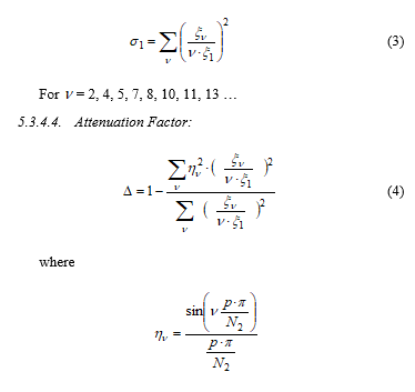
5.3.4.3. Differential Leakage Coefficient:
For = 2, 4, 5, 7, 8, 10, 11, 13 …
5.3.4.4. Attenuation Factor:
 with the rotor slot number that cannot be infinite here.
5.3.5. Harmonic Torque:
It is not within the scope of this paper to take a position between the different approaches on how to calculate harmonic torques. For the sake of good transparency, the method given in [17] p. 112. (240a) will be followed here:
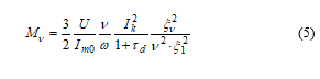 Where
Where
– phase supply voltage
– magnetizing current (fundamental)
– short circuit current (fundamental)
– differential leakage coefficient
For obtaining a more simple formula that gives quick values for comparison, some further formulas will be introduced and certain approximation will be made as follows:
fundamental
– with stray reactance
– with magnetizing reactance
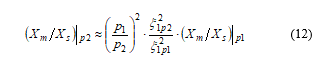
By inserting the above three approximate relations into (5) and by rewriting the following formula will be obtained:
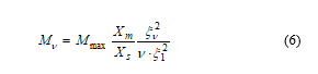 If both Xm and Xs will be put in p.u. a quick estimation will be obtained for the maximum torque of the harmonic in relation to the maximum torque of the fundamental wave.
This formula must be applied for 2p1 and 2p2 pole number separately because also p.u. values of Xm and Xs are different on each pole number.
From parasitic torque point of view the 4th harmonic is the critical one, because its rotation is in the motor range, in other words the sense of rotation is the same as that of the fundamental field. The 2nd harmonic is rotating opposite sense therefore it has no influence on the motor range unless its break-down torque is extremely high and its effect (although acting in brake-range) “reaches” the motor range. Anyway, harmonics’ torque may be reduced linearly by reducing magnetizing reactance (= increasing no-load current) see [17] p. 112, equ (240a): which may be a reasonable compromise. 4th harmonic torque has less effect at a drive with parabolic counter-torque like pump, fan etc. Corresponding effect on motor derating k3 is discussed under item 5.3.9. Derating. of this chapter.
From differential leakage point of view, however, the 2nd harmonic is the critical one, because its influence on the differential leakage may be dramatic, although having highest attenuation. Therefore, for example, pitch degree of 270° is not recommended, although 4th harmonic would disappear but 2nd harmonic is just on maximum.
In case of critical situation regarding too high 4th harmonic, the following method can be applied: the “last” slot or slots in each phase belt will be left without winding. By doing so the phase belt will be less than 120°, or with other words, it gets one-step closer to phase belt 90°. If 90° phase belt were reached, there would be no 4th harmonic – as known from the theory.
Obviously, each “empty” slot requires further derating of the motor, therefore just a moderate use of this method is recommended, also because further harmonics may be generated at the other pole number; see k4 under item 5.3.9. Derating. of this chapter. Calculations show that practically no change of differential leakage is expected by doing so.
5.3.6. Maximum Fundamental Torque on p1 and p2 Pole Numbers, Air-gap Induction
The fundamental air gap flux will be determined first and then the maximum torque will be estimated on both pole numbers. The expression of voltage and flux will be written as known:
![]() with – supply frequency
with – supply frequency
– flux per pole
– number of turns per phase.
As the N number of turns per phase is definitely identical on both pole numbers, it follows that is necessarily identical also. Because the maximum torque is proportional to
![]() the following will be obtained:
the following will be obtained:
![]() This means the absolute value of maximum torque on the higher pole number is definitely higher than that on the lower pole number. The motor operation may be called as “constant power operation”.
This means the absolute value of maximum torque on the higher pole number is definitely higher than that on the lower pole number. The motor operation may be called as “constant power operation”.
Furthermore, with
with D – air gap diameter
L – equivalent length of iron core
B – air gap induction mean value
Inserting it into (7) the following formula is obtained:
![]() As important information for the designer, it is established that the air-gap induction on the higher pole number is (much) higher than that on the lower pole number.
As important information for the designer, it is established that the air-gap induction on the higher pole number is (much) higher than that on the lower pole number.
5.3.7. Ideal pitch
Because the pitch is practically the only tool in the hand of the designer the question arises whether the optimum or “ideal” pitch may be found or not. Figure 6. will help in the consideration.
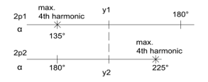 Figure 6. Sketch for explaining “ideal” pitch
The sketch indicates the electrical angles of both pole numbers, around 180° as “full pitch”, as well as those dangerous pitches which should be avoided. The coincidence of y1 and y2 demonstrates that the mechanical pitch is necessarily identical. Therefore
While moving y1 towards 180°, the harmonic content (incl. 4th harmonic) on the lower pole number will always be more and more advantageous, but, at the same time it will always be more and more disadvantageous on the higher pole number until it reaches unacceptable extent, and vice-versa see also in 5.3.3. above.
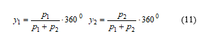
The right pitch shall be somewhere in between. A possibility to choose y1 and y2 in a way that
At such choice the winding factors of all harmonics as well as the fundamental will be identical on both pole numbers.
The resulting pitches are
 Harmonic torques p.u. value as given in (6), however, will still not be identical because they are further dependent on the ratio of Xm and Xs, and those are different for each pole number. Further consideration is necessary in this respect.
Passing over detailed deduction it is obtained that
is proportional to
while however, remains approximately constant (more precisely it reduces slightly).
It is obtained at the end that the ratio Xm / Xs valid for the lower pole number will change when connected to the higher pole number according to the following way:
 This expression shall be inserted into (6) for direct calculation of harmonic torques on the higher pole number. It is underlined that the formulas give the harmonic torque referred always to its own maximum fundamental torque (in p.u.).
Targeting equal 4th harmonic torque (p.u.) on both pole numbers as a good compromise, the above formula tells that y1 and y2 according to (11) will not provide the expected results as the harmonic torques will be much less for the higher pole number. Therefore, y1 may be moved a bit towards 180° by reducing chording on the lower pole number. Because of the non-linearity ( sin() in both winding factors, ξ2 in the torque expression ) this “ideal” pitch cannot be given in a definite formula.
y2 – obviously – must not be moved too close to 225°.
For a full picture, the calculations by the formulas in 5.3.4.3 and 5.3.4.4 give that
- this “targeted” pitch (although for infinite slot numbers) will result in such “high” magnitude of differential leakage coefficients as given in the literature for q = 3 or so. This is due to the presence of (low-order) even harmonics.
- at the same time it results in lower attenuation factors than given in the literature due to the strong attenuation effect of the rotor just on the low-order even harmonics.
Expected approximate harmonic torques for 6/8 pole at that chording for best compromise:
| 6 pole | 8 pole | ||
| M4 / Mmax | 0.16 | M4 / Mmax | 0.16 |
| M7 / Mmax | 0.007 | M7 / Mmax | 0.006 |
| M10 / Mmax | 0.023 | M10 / Mmax | 0.001 |
This example represents the limit of application in respect of pole ratio (min. 0.75) without balancing measures.
5.3.8. Parallel Connection of the Winding
For high power motors, further parallel connection of the winding may become necessary. It is, unfortunately, not possible for the smallest pole numbers, e.g. for 6-8 pole or such. It is possible, however, for higher pole numbers: for 12-16 pole further 2// connections, for 18-24 pole further 3// connections become possible, for example.
5.3.9. Necessary Derating of the Basic One-Speed Motor
Based on the above considerations, the necessary derating of such double-speed motor can be defined compared to the basic single-speed motor. To put it differently: considering a certain size of a single-speed motor with P [MW] power and 2p1 pole number, what can be the power P1 of such double-speed motor with the same lower pole number 2p1. P2 belonging to 2p2 (the higher one) is not important, because the load at the higher pole number is always considerably lower.
There are 4 factors for necessary derating:
![]() Each coefficient is < 1, according to the followings:
Each coefficient is < 1, according to the followings:
k1 derating due to the ratio of the winding factor for 60° and 120° belt and for the pitch. The belt factor ratio is always the same: 0.827 / 0.955 = 0.866 which is the value of inherent derating necessity derived directly from the theory of this method. Then, this should be multiplied by the ratio of the actual (lower pole number) pitch shortening factor compared to the usual 5/6 shortening factor. This later ratio is usually again less than 1.
k2 derating due to excess loss caused by the balancing currents due to imbalance of stator phase angles. This only applies in case the lower pole number is not integer multiple of 6, otherwise k2 = 1
k3 derating necessity due to eventual excess loss caused by eventual necessity of increasing no-load current, which causes the rated current to increase because of the decreased cos φ. For further details see Harmonic Torque 5.3.5.
k4 derating necessity in case where phase belt should be less than 120°, again see Harmonic Torque 5.3.5.
Overall derating necessity is expected to be 75 – 80% (example: a 6 MW single speed motor size may be loaded by 4.5 – 4.8 MW if wound for 3// Y / 3 //Y for any pole number).
5.4. Conclusion, proposal for application
Any pole number combination can be implemented by the prescribed method.
Based on the voltage imbalance and the calculation of the harmonic torques it can be established, however, that the method may be applied
- for 6 poles and above and
- for pole ratios of 0.75 and higher (very close ratios)
without any balancing measures in the winding.
The method is recommended especially for driving such machines as pumps, fans etc.
It is underlined that such pole combinations like 4-6, 6-10 etc. can be implemented also. The high unfavorable effects of the even harmonics and phase imbalance appearing here may be eliminated by balancing measures.
6. Application of the method for wide ratio
6.1. General Considerations
Now it will be investigated as a new field of research whether the method can or cannot be applied for pole numbers being very far from each other, generally called wide ratio. The easiest investigation involves a 1 : N ratio where N is integer.
If N is even, such as 2, 4, 8, etc. and symmetrical pitch (=full pitch) is chosen on the lower pole number, as logical first approach for avoiding even harmonics, there will be no excitation on the higher pole number (it is easy to understand that U and –U are in the same slot and therefore magnetomotive force of each slot is zero). As a consequence, such motor simply does not work. If, however, y1 will be moved to either direction, but preferably towards lengthening, the machine will work on both pole numbers, but even harmonics appear also on both pole numbers; the calculation method can be obtained again from the previous chapter.
If N cannot be divided by 3 such as 4, 5, 7, 8 etc. the 3// connection cannot be implemented at all, because the 3 groups cannot be identical, as one phase is always and considerably different from both the other phases.
If N = 3 (3, 9 etc.), however, like a 6 – 18 pole changing winding, the result is absolute ideal, no even harmonic will appear on either pole number, therefore the motor’s behavior on both pole numbers is identical to the corresponding single-speed motor.
This statement may be supported very easily.
If “full pitch” will be chosen on the lower pole number, as the logical first approach for avoiding even harmonics as before then the same mechanical pitch will result in
electrical pitch for the higher pole number.
If N is even the electric angle for the higher pole number is always
It means that there will be no fundamental wave on 2p2 at all.
If N is odd, however, the electric angle for the higher pole number is always
, full pitch
This is the reason why the machine will work as a standard one on both pole numbers, but always with full pitch. No further
 Figure 7. Slot distribution pattern for 1:3 as well as for 1:6 pole ratio
scientific considerations are required and the designer may apply basically his standard software (but for 120° phase belt).
Based on this principle the slot distribution pattern for 1:3 pole ratio and for 1:6 pole ratio can be created easily (Figure 7). The lower layer is indicated only. Continuing in the same way the slot distribution and connection pattern also for 1:9, 1: 12 …etc. pole ratio can be created. See connection pattern for 1:3 pole ratio on Figure 8..
However, further investigation shows that in such cases (N=3, N=6 etc.), phase asymmetry will always appear again, on the lower pole number only, the nature of which is the same as in 5.1, but the magnitude is much higher. It is even so high that a solution must be found to eliminate it.
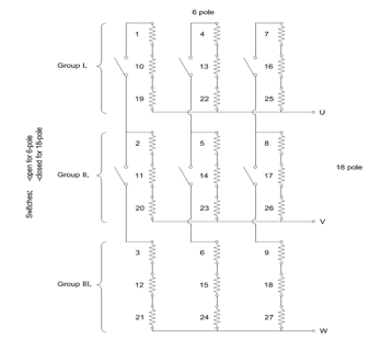 Figure 8. Pole changing connection pattern for 1:3 pole ratio
6.2. Specific Considerations for the Lower Pole Number
The lower pole number on Figure 7. will be discussed again. Comparing it with Figure 8.. it comes clear that Group I. contains always the “beginning part” of the pole, Group II. the “middle part”, Group III. the “last part”.
Figure 9. shows as final result the phase angles of the induced voltages for each Group to be connected in parallel, in true scale.
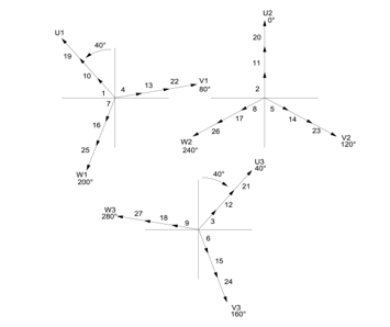 Figure 9. Voltage vector pattern for 1:3 pole ratio
Supplying the – parallel connected – Group I, Group II and Group III. with the same 3-phase system, then considerable balancing currents will be generated by that always 40° phase imbalance. Although there is wide ratio here, the approach of calculation method given in Appendix may be applied. Nevertheless, no need for any further calculation (neither that of extreme difference in the currents nor additional torque ripples in the motor caused by local air gap induction variation) to see that it exceeds any tolerance range.
Instead of looking for solutions in the machine (losing its simplicity) a solution in the supply is more recommended this time.
In order to avoid balancing currents, the following shall be done:
Group I. shall be supplied
by a 3-phase system -40° – 80° – 200°
Group II. shall be supplied
by a 3-phase system 0° – 120° – 240°
Group III. shall be supplied
by a 3-phase system 40° – 160° – 280°
Just a clear 9-phase supply system has been reached in this way.
Consequently, the only possibility for avoiding balancing currents in pole numbers 2p – 3x2p or 2p – 6x2p, etc. is to have nine terminals for the lower pole number.
Such solution was already proposed by [9], but through a completely different way of consideration and actual connection arrangement, and then continued in [10] and [11] but as a result of a particular consideration, only for 1:3 ratio.
For creating 9-phase system, frequency converters may be used. The converter is connected into 3-parallel (not unusual for high power) and the regulation of each parallel branch is shifted by 40° from each other, see Figure 10.
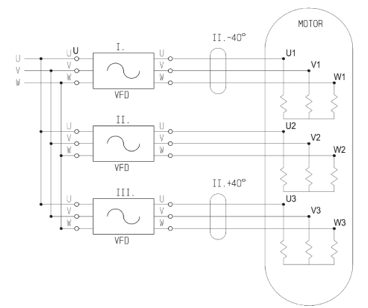 Figure 10. Proposal for supply of the stator winding on the lower pole number
As a consequence, no further derating other than the inherently k1 = 0.866 is necessary to apply in case of 1:3 (1:9 etc.) pole combination.
Such shifting of 40° is not necessary for the higher pole number, which may thus preserve its 3-phase winding – 3-phase supply – 3-terminal. When changing the supply to the higher pole number, the nine terminals of the lower pole number (always 3-3-3 of the same phase) must be short circuited by a separate switch.
What having found contributes to conceptualize the ideal driving system of very high power motors for main marine propulsion application where greatly different speeds are required, such as cruising speed and manoeuvring speed and the speed regulation of the driving – also if not single speed but pole changing motors are applied – is carried out by frequency converter.
The same energy supply concept shall be applied for the lower pole number in case of 6-36 pole, 6-54 pole etc. that means for 1:6, 1:9, etc. pole ratio as well.
Mechanical pitch corresponds always to that of the lower pole number. This mechanical pitch (endwinding construction) is very far from the usual ones at standard high pole motors. That is the only fact to be taken into consideration when electromagnetic calculation is being performed by standard calculation software.
6.3. Further extension of the approach: 1:4, 1:5, 1:7… pole ratio
A motor winding supplied by the usual 3-phase network has been investigated so far. Therefore, some limitations have appeared, such as 1:4, 1:5, 1:7 etc ratios have not been possible. If, however, this approach is exceeded, and the number of the phases is extended, as a very new approach, those missing pole ratios became possible immediately and very easily. 1:4 pole ratio is possible to achieve by 4-phase supply and 4//Y / 4//Y connection, 1:5 pole ratio by 5-phase supply system and 5//Y / 5//Y connection, 1:7 pole ratio by 7-phase supply system and 7//Y / 7//Y connection and so on.
As an example, the slot distribution pattern as well as connection pattern for 5 phase 5//Y / 5//Y connection is given on Figure 11. and Figure 12., resp. just for demonstration (for which the slot distribution pattern is only its beginning part, for the sake of good visibility and readability only). It is to be continued for N phase N//Y / N//Y connection in the same way.
Some conclusions found before still valid. Supply concept on the lower pole number must be applied similarly to Figure 10. in order to avoid those extreme balancing currents.
As a consequence, the number of the terminals will increase according to the number of the phases, also because NxN phase supply is necessary for the lower pole number.
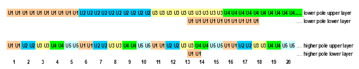 Figure 11. Slot distribution pattern for 1:5 pole ratio
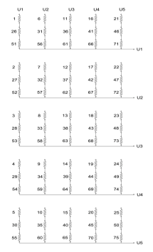 Figure 12. Connection pattern for 1:5 pole ratio (5 phase supply)
Further, what found before for the case if N is even or odd, is still valid. If N is even, like 1:4, even harmonics will appear. If N is odd like 1:5, 1:7 etc. the result again is absolute ideal, no even harmonic will appear on either pole number, therefore the motor’s behavior on both pole numbers is identical to the corresponding single-speed motor. Derating factor of k1=0.866 is still valid.
Due to the high number of parallel connection – high number of phases is also a certain kind of parallel connection – the method is inherently suitable for high power.
6.4. Rotor slot numbers
The literature gives little support for how to choose the rotor slot numbers.
For standard motors there are a number of proposals for which the forbidden and which the proposed slot numbers are. As a first step not more than those basic requirements known from the theory will be considered:
- q number of slots per pole per phase must not be an integer (for avoiding synchronous harmonic torque at zero speed)
- number of rotor slot number per 2p must be an integer (for avoiding imbalanced magnetic pull).
Considering these for both the higher as well as the lower pole number a clear picture can be obtained, preferable on a usual spreadsheet.
The result is the following:
- there is no common slot number on the sheets because
- each slot number proposed acc. to 2nd requirement for higher pole number are forbidden slot numbers acc. to 1st requirement for the lower pole number. The reason is that each gives an integer q for the latter.
- no any on the (long) list of proposed slot numbers of the lower pole number can be found on the (shorter) list of the higher pole number.
It is clear in this way that it is impossible to find a rotor slot number which would fulfill even those minimum requirements above at the same time.
What in this situation can be preferred is the lower pole number – because of the higher speed – unless the generally higher air gap induction on the higher pole number seems to make more problems.
6.5. Supply voltage strategy
It was obvious in the chapter 5. for close ratio that the supply voltage for both pole numbers is the same. It is not necessarily the case, however, here. Therefore, it may be discussed shortly what supply strategy may be possible when switching from the lower pole number to the higher pole number and what the consequences are.
The formulas already found in chapter 5.3.6. will be applied. The case for N = odd will be discussed only just for more compact formulas because here the pitch is identical (full) pitch on both pole numbers therefore: and the consideration can focus on the important phenomena.
The logical target – when determining the power – will always be to obtain identical maximum torque expressed in p.u. on both pole numbers (Mmax /Mrated remains). Therefore, the ratio of the maximum torque absolute values will be expressed as being proportional with the square of the voltage.
6.5.1. Same voltage
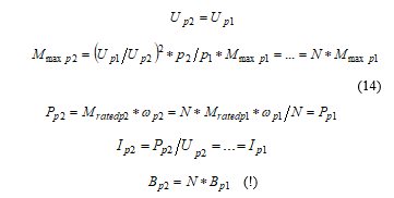 The operation corresponds to “constant power”.
The result is obviously identical to that obtained in 5.3.6 for close ratio.
6.5.2. Voltage reduced by
 The operation corresponds to “constant torque”.
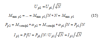
6.5.3. Voltage reduced by N
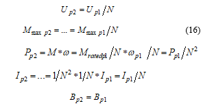 The operation could be named as “constant stress of motor”.
It shall be remarked that all the above formulas regarding the current are valid only if the (eventual) change of η and cos φ is out of consideration.
It shall be remarked also that – when connected to p2 – the induction in the iron core will be changed in an unusual way:
Btooth changes proportional to Bairgap ;
Byoke changes proportional to Bairgap / N .
The right strategy may be chosen acc. to the torque requirements of the drive.
7. Conclusion
In this paper, a complete analysis of 3//Y / 3//Y pole changing method has been provided through a unique approach, including application, characteristics and design aspects in a comprehensive way, especially for high power motors.
The main finding of the analysis is that the method is suitable for any pole combination, with no limitation for both close ratio as well as for wide ratio pole changing windings.
It has been proven for close ratio that the method is well applicable without balancing measures for practically the whole range required by the industry. The limits are given and are supported by calculations.
Moreover, as a fundamental novelty, a solution for a theoretically infinite range of 1:N pole change ratio winding connection has been given (N phase N//Y / N//Y connection), with no need for further scientific considerations, that means it is suitable for a direct industrial use. The designer may use his standard calculation software.
A new, complete drive system for main marine propulsion has been proposed, with the pole changing motor with 1:N ratio as the core element.
8. Appendix
8.1. Approximate calculation of balancing currents discussed in connection of Figure 4.
The phenomenon was simple mentioned already in [6] but with little explanation, no calculation.
Because the phenomenon arises in no-load as well, even, the phenomenon is in connection with the main flux and the induced voltage by the main flux, the simplified equivalent circuit known from the theory may be applied.
This simplified equivalent circuit shall be applied for each parallel branch see Figure 13.. The voltage of the branches is the same: U, the supply voltage. The currents, however, are obviously different: they will be expressed by the sum of the common, resulting (magnetizing) current and the equalizing current I + ΔI. Regarding reactance and the induced voltage, not only the value but its direction must be taken into consideration in the meaning that the phase of the induced voltage will be different in different winding parts acc. to their position: that is why the reactance representing those “last 2 poles” are multiplied by , 1, resp.
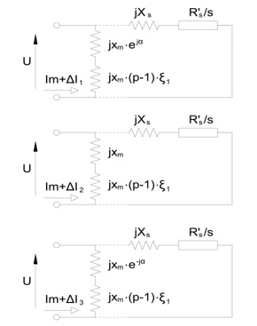 Figure 13. Simplified equivalent circuit
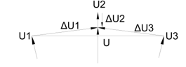 Figure 14a. Voltage vector diagram
Vector diagrams of the voltages and of the currents for no-load and load – based on Figure 4. – are shown on Figure 14a. and Figure 14b. The latter one is not in true scale.
The equations for the 3 parallel branches will be:
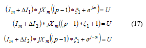
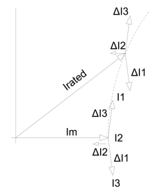 Figure 14b. Resulting equalizing currents
where
– resulting, equivalent magnetizing current of one parallel branch
– magnetizing reactance per pole per branch
– takes into account that the “first 6 poles” are full poles
– takes into account the phase of the induced voltage in the “last 2 poles”, where the winding coefficient of these winding parts is approximated to be 1; α = 40°
– supply voltage.
Because the sum of the equalizing currents is per definition zero, if all three equations are added, it yields
![]() Actually, although is given in this way, the main target is to knowcompared to as the imbalance in p.u.:
Actually, although is given in this way, the main target is to knowcompared to as the imbalance in p.u.:
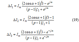 Magnitudes of the equalizing currents are (for 8 poles) approximately:
The phase angle is also interesting in case of further considerations because e.g. ΔI2 results in local decrease while ΔI1 and . ΔI3 do so in local (half so much) increase of airgap induction which causes torque ripples and local radial force fluctuation.
Above equations are valid for 8, 14, 20 etc. poles. In case of 10, 16, 22 etc. poles
shall be substituted by and
, 1, shall be substituted by , 2, resp.
Conflict of Interest
The author declares no conflict of interest.
- G. Kovács, “A 3Y / 3Y Winding for high Power Asynchronous Motors”, World Academy of Science, Engineering and Technology International Journal of Electrical and Computer Engineering Vol:12, No:1, 2018. p. 1367-1374
- Lengyel Zoltán, “Korszerű kéttekercselésű motorok”, in Hungarian. Ganz Közlemények, Proceedings of Ganz Electric Works 1964. p. 31 – 36.
- G. H. Rawcliff, B. V. Jayawant, “The development of a new 3: 1 pole-changing motor”. Proceedings of the IEE – Part A Power Engineering 1956. p. 306 – 316.
- T. H. Barton, O.I. Butler, H. Sterling, “The theory and Characteristics of the new 3:1 pole changing induction motor”, Proceedings of the IEE – Part A: Power Engineering 1956 p.285 – 294.
- K.C. Rajaraman, “Design criteria for pole-changing windings”, Proceedings of the Institution of Electrical Engineers ( Volume: 124, Issue: 9, September 1977 ) 775 – 783, https://doi/org/10.1049/piee.1977.0171
- A.R.W. Broadway ; K.S. Ismail , “Phase modulated 3-phase pole changing windings”, IEE Proceedings B – Electric Power Applications 1986 p. https://doi.org/10.1049/ip-b.1986.0011
- P. Chidambaram ; M. Subbiah ; M.R. Krishnamurthy, “Developments in Pole Changing Windings using Star/Star-Delta Switching”, IEEE Transactions on Energy Conversion ( Volume: EC-1, Issue: 4, Dec. 1986 ) p. 135 – 141 https://doi/org/10.1109/TEC.1986.4765787
- K.C. Rajaraman, W. Ranjith Perera, G. Subramaniam, “New wide-ratio pole-changing motors”, IEE Proceedings B – Electric Power Applications ( Volume: 134, Issue: 4, July 1987 ) p. 211 – 214 https://doi.org/ 10.1049/ip-b.1987.0036
- J.W. Kelly ; E.G. Strangas ; J.M. Miller, “Control of a continuously operated pole-changing induction machine”, IEEE International Conference on Electric Machines and Drives. 2003 IEMDC’03. https://doi.org/10.1109/IEMDC.2003.1211265
- Gautam, J. Ojo, “ Variable speed multiphase induction machine using pole phase modulation principle”, IECON 2012 – 38th Annual Conference on IEEE Industrial Electronics Society 2012. https://doi/org/10.1109/IECON.2012.6389310
- Umesh B S, Kiran Kumar N, Sivakumar K, “Performance improvement of a nine phase pole phase modulated induction motor drive”. IEEE International Conference on Industrial Technology, 2015 p.812-817. https://10.1109/ICIT.2015.7125198
- Baoming Ge ; Dongsen Sun ; Weiliang Wu ; Fang Zheng Peng , “Winding Design, Modeling, and Control for Pole-Phase Modulation Induction Motors” IEEE Transactions on Magnetics ( Volume: 49, Issue: 2, Feb. 2013 ) p. 898 – 911 https://doi/org/10.1109/TMAG.2012.2208652
- Dawei Meng, Qian Wang, Research on Balanced Winding Used in 3Y/3Y pole changing Motor, – International Journal of Automation and Power Engineering (IJAPE) Volume 2 Issue 4, May 2013
- H. Liu, J. Wang, Z. Zhang, Performance analysis of variable speed multiphase induction motor with pole phase modulation, Archives of Electrical Engineering, Vol. 65(3) 2016. p. 425-436
- W. Nürnberg, “Die Asynchronmaschine”, in German, Springer Verlag 1952. p.299.
- Liska József, “Villamos gépek, IV. Aszinkron gépek”, In Hungarian, Tankönyvkiadó Budapest 1960. p. 126.
- Bedrich Heller, Václáv Hamata, “Harmonic Field Effects in Induction Machines”, ELSEVIER Scientific Publishing Company Amsterdam, Oxford, New York 1977