
Abstract
Introduction:
The real-time measurement of active power delivered to patients during the electrosurgical act is still an engineering challenge. Besides, there is no electrosurgical unit on the market capable of doing it according to the normative requirement.
Methods
This work presents the design of an electronic structure capable to probe the electrosurgical equipment output electrical signals, using low-costs very common resistors, and High Frequency distortions compensation circuits, and process them to provide an analogue signal proportional to the active power, allowing the knowledge and control of the energy delivered to the biological tissue. The reading circuits and the active power calculation method are presented. The power calculation is performed in two stages. The first one consists of a multiplier circuit that uses the readings voltage and current quantities to determine the instantaneous output power, and the second stage is formed by an integrating circuit which determines the average power value, resulting in a rippled continuous voltage, proportional to the active power delivered to the patient or biological tissue.
Results
Practical tests of the compensation technical are statistically evaluated by means of linear regressions. Results of 23 tests are summarized in a way to demonstrate de effectiveness of the proposed system.
Conclusion
Analysis of the results demonstrate the efficiency of the proposed system, whose average error is lower than 5%, and correlating them with the standard IEC 60601-2-2, that regulates the operation of electrosurgery units.
Keywords
Electrosurgery; Active power; Analogue multiplier; Analogue integrator; HF current probing; HF voltage probing
Introduction
The use of high frequency voltages, higher than 200 Vpeak, and high current density, producing sparks, is the principle of the electrosurgery signals. These signals can produce incisions, destroying and/or removing organic tissues with the promotion of hemostasis. Usually the output power is up to 300 W with current intensities up to 3 A and operations frequencies from 300 kHz up to 5 MHz (International…, 2013International Electrotechnical Commission – IEC. IEC 60601-2-2: medical electrical equipment. Part 2-2: particular requirements for the basic safety and essential performance of high frequency surgical equipment and high frequency surgical accessories [internet]. Geneva: IEC; 2013. [cited 2017 May 17]. Available from: http://www.iec.ch/index.htm 2013
http://www.iec.ch/index.htm...
). Actually, commercial equipment have switched output and operates below 750 kHz (Schneider, 2004Schneider B Jr. Estudo teórico-prático de parâmetros técnicos e fisiológicos utilizados em eletrocirurgia, visando a otimização do desenvolvimento e performance de um bisturi eletronico [thesis]. Curitiba: Centro Federal de Educação Tecnológica do Paraná; 2004.).
Even after a century of the beginning of this technology, many scientific and technological problems remain to be solved. A poorly regulated or incorrect used of electrosurgery unit (ESU) can cause patient problems, such as tissue carbonization, DC burns in unwanted places and even the undesired electrostimulation (Schneider and Abatti, 2008Schneider B Jr, Abatti PJ. Electrical characteristics of the sparks produced by electrosurgical devices. IEEE Trans Biomed Eng. 2008; 55(2):589-93. PMid:18269994. http://dx.doi.org/10.1109/TBME.2007.903525.
http://dx.doi.org/10.1109/TBME.2007.9035...
).
Aiming to understand the electrosurgery phenomena, and thus to improve the regulation and the correct use of these equipment, researchers have tried to develop systems that allow an efficient control of the output active power of the ESU. Some studies have been conducted in the direction of determination and regulation of the delivered power, although none of them has reached yet the point of sufficient development to be integrated into medical equipment. It is important to mention that in order for an equipment to be able to display wattage in its panel, it must deliver active power with a maximum error of 20% in relation to the panel set point value (International…, 2013International Electrotechnical Commission – IEC. IEC 60601-2-2: medical electrical equipment. Part 2-2: particular requirements for the basic safety and essential performance of high frequency surgical equipment and high frequency surgical accessories [internet]. Geneva: IEC; 2013. [cited 2017 May 17]. Available from: http://www.iec.ch/index.htm 2013
http://www.iec.ch/index.htm...
). This is a very difficult task because the organic tissue changes dynamically its impedance under the active moving electrode, mainly due the difference between muscle, fat, nerve, bone and other organic tissues.
In the 1980s, efforts were focused on the power determination from proportional parameters of the output magnitudes (Schmitt et al., 1983Schmitt OH, Tucker RD, Sievert CEJ Jr, Silvis SE. A miniature current probe for measuring electrosurgical currents. Med Instrum. 1983; 17(4):276-7. PMid:6633320.; Tucker et al., 1989Tucker RD, Stasz PS, Kramolowsky EV. A simple and inexpensive method for measuring electrosurgical variables. Biomed Instrum Technol. 1989; 23(1):54-7. PMid:2924053.). From the end of the 1990s, efforts were made to determine the power through computational tools (Fritz and Schall, 2014Fritz M, Schall H. Electrosurgical generator for the treatment of a biological tissue, method for regulating an output voltage of an electrosurgical generator, and corresponding use of the electrosurgical generator. United States patent US 8920412B2. 2014 Dec 30.; Monteiro et al., 2016Monteiro ALR, Grande KC, Faria RA, Schneider B Jr. A simple approach to calculate active power of electrosurgical units. Res Biomed Eng. 2016; 32(1):14-27. http://dx.doi.org/10.1590/2446-4740.0776.
http://dx.doi.org/10.1590/2446-4740.0776...
; Visser et al., 1991Visser H, Fastenmeier K, Mausberg R, Lohr G. Measurement of physical parameters in HF surgical techniques in dentistry. ZWR. 1991; 100:219-23.; Zhou et al., 2014Zhou Y, Li D, Xu W, Song C. A new parameter measurement system for electrosurgery output. Sheng Wu Yi Xue Gong Cheng Xue Za Zhi. 2014; 31(2):421-5. PMid:25039153.) and the new topologies development, where new control techniques could be employed (Friedrichs et al., 2012Friedrichs DA, Erickson RW, Gilbert J. A new dual current-mode controller improves power regulation in electrosurgical generators. IEEE Trans Biomed Circuits Syst. 2012; 6(1):39-44. PMid:23852743. http://dx.doi.org/10.1109/TBCAS.2011.2159859.
http://dx.doi.org/10.1109/TBCAS.2011.215...
; Jensen and Maksimovic, 2017Jensen S, Maksimovic D. Fast tracking electrosurgical generator using two-rail multiphase buck converter with gan switches. IEEE Trans Power Electron. 2017; 32(1):634-41. http://dx.doi.org/10.1109/TPEL.2016.2524642.
http://dx.doi.org/10.1109/TPEL.2016.2524...
; Schneider and Abatti, 2005Schneider B Jr, Abatti PJ. Desenvolvimento de um equipamento eletrocirúrgico com saída não chaveada. Rev Bras Eng Bioméd. 2005; 21:15-24.; Wurzer et al., 1997Wurzer H, Maeckel R, Lademann J, Audring H, Liess HD. A spark counter as a control unit of a radio frequency surgery device. IEEE Trans Biomed Eng. 1997; 44(9):831-8. PMid:9282475. http://dx.doi.org/10.1109/10.623052.
http://dx.doi.org/10.1109/10.623052...
). Unfortunately, these techniques are either inefficient or have a high implementation cost, which makes their commercial application not practical.
This work presents a low-cost technique that allows to determine the ESU active power delivered to a patient with an acceptable error. A technic that turn possible the real-time active power measure (and after the control) can be very useful to avoid damage in the organic tissue. Due to the fact that it does not use computational tools, the output quantity, in this case a continuous voltage, is determined in almost real time and presents an average value proportional to the active power delivered in the procedure. If we consider a 10 mm/s speed incision, a dynamic response in less than 1 ms represents less than 0.01 mm of displacement, which is a very small area that could be damaged before the regulation of the output power. For this reason, a response time of 1 ms for the active power calculation is one goal of this work.
Methods
An useful shortcut to get the active power, also called average power or DC power, is to take the integral of the product between instantaneous voltage and current over one or more complete periods (Institute…, 2010Institute of Electrical and Electronics Engineers – IEEE. 1459-2010: IEEE standard definition for the measurement of electric power quantities under sinusoidal, nonsinusoidal, balanced, or unbalanced conditions. New York: IEEE; 2010. p. 1-50. http://dx.doi.org/10.1109/IEEESTD.2010.5439063.
http://dx.doi.org/10.1109/IEEESTD.2010.5...
), as indicated in Equation 1.
In Equation 1, v(t) is the instantaneous voltage, i(t) is the instantaneous current, T is the period of the signals and n is the number of considered periods.
To implement this solution a system, presented in Figure 1, is proposed. The output quantities v(t) and i(t) of an ESU are read by means of two probing circuits: One for instantaneous output voltage, which is the v(t) term of Equation 1 and is probed as vv(t) in the Figure 1; and other for instantaneous output current, which is the i(t) term of Equation 1 and is probed as vi(t) in the Figure 1. These values are multiplied and the output signal, represented by p(t), is filtered by a lowpass filter, determining a continuous voltage, which approach, in an analog way, the active power P. If the cutoff frequency is much lower than the signals v(t) and i(t) frequency, a similar result to the average value integration for a great number of periods will be achieved.
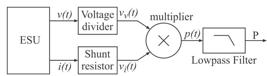
Block diagram of the reader system and calculation of the active power. v(t) is the output voltage and i(t) is the current of an ESU, vv(t) and vi(t) are the voltage and current readings respectively, p(t) is the instantaneous output power and P is the active power.
To proceed the tests, the measure configuration presented in Figure 2 was used, where AE indicates the Active Electrode and PE indicates the Passive Electrode. A Rode & Schwarz Hameg oscilloscope model HMO2024 was used in a sampling resolution of 1 GSa/s per channel (Rohde…, 2011Rohde & Schwarz Company. Digital Oscilloscope HMO Series 72x ... 202x [internet]. Melrose: HAMEG; 2011. 48 p. [cited 2017 May 20]. Available from: https://www.utwente.nl/tnw/slt/doc/apparatuur/oscilloscopen/hameg-man-en-hmo72x-202x.pdf
https://www.utwente.nl/tnw/slt/doc/appar...
) and were produced samples with 6000 acquisition points. A 50 MHz Tektronix P5200A isolated differential voltage probe, at channel A, and a 60 MHz Tektronix P6021A isolated current probe, at channel B, were also used to directly measure the output quantities of the electrosurgical equipment, as well as two non-isolated 100 MHz Tektronix X1/X10 probes that were used to read the magnitudes of the readings and the power calculation circuits. All tests were performed on a ESU prototype with a sine-wave output (Bernardi, 2007Bernardi R. Desenvolvimento de um equipamento para estudo de eletrocirurgia com controle de potência ativa [dissertation]. Curitiba: Universidade Tecnológica Federal do Paraná; 2007.; Schneider and Abatti, 2005Schneider B Jr, Abatti PJ. Desenvolvimento de um equipamento eletrocirúrgico com saída não chaveada. Rev Bras Eng Bioméd. 2005; 21:15-24.) operated at 400 kHz. In this ESU, voltages up to 700 V and currents up to 2 A were expected. As test body, replacing the biological tissue, a slice of Chayote (Sechium edule sp.) (Schneider and Abatti, 2008Schneider B Jr, Abatti PJ. Electrical characteristics of the sparks produced by electrosurgical devices. IEEE Trans Biomed Eng. 2008; 55(2):589-93. PMid:18269994. http://dx.doi.org/10.1109/TBME.2007.903525.
http://dx.doi.org/10.1109/TBME.2007.9035...
) with 10 mm thickness was used due to the fact there is no significant differences between it and swine flash. This kind of test body can produce output powers up to 40 W in cut mode and 100 W in coagulation mode. The oscilloscope was isolated from the AC electrical network by an isolating transformer at low frequencies and the inclusion of two high frequency decoupling shock inductors of 4.3 mH.

Patient circuit and oscilloscope probes locate. AE is the active electrode, AE-output is the connection of this electrode to the ESU, PE-plate is the passive electrode and PE-input is the connection of this electrode to the ESU. REF is the reference point of acquisitions, v(t) is the output voltage and i(t) is the output current, vv(t) and vi(t) are the voltage and current readings respectively.
In the experimental analysis, some power measurement and calculation structures results are presented and discussed, as well as the errors are compared to the standards limits.
Voltage and current probes circuit
To read the voltage and current at the output of the electrosurgical equipment with low cost, a resistive voltage divider and a shunt resistor were respectively used. Knowing that these circuits insert distortions in the read signals at high frequency, because of the construction characteristics of the resistors (Ludwig and Bretchko, 2000Ludwig R, Bretchko P. RF circuit design: theory and applications. Upper Saddle River: Prentice-Hall; 2000., p. 15), some models were tested in an impedance analyzer Agilent 4294A.
These tests were made with axial ¼ W carbon resistor, 1206 SMD carbon resistors and 5 W wire resistor. According to them it was possible to define that, in frequencies up to 100 MHz, for all tested resistors up to 470 Ω, the behavior is like a resistive and inductive (RL) series circuit, due to the increase of magnitude and phase angle along the increase of the frequency. For tested resistors above 470 Ω this behavior becomes capacitive, like a resistive and capacitive (RC) parallel association, due to the decrease of the magnitude and phase angle along the increase of the frequency.
The simple use of these resistors in high frequency reader circuits can produce some significant measurement errors. Considering that electrosurgery waveforms usually presents harmonic distortions due to the sparks, that the resistors of the voltage divider are higher than 1 kΩ and the shunt is a 1 Ω wire resistor, the voltage and current harmonics will be amplified and will have the phase angle advanced, in relation to their real values, resulting in significant measurement error.
In order to work around these problems, some compensation techniques were applied to these structures. For the voltage divider circuit, a compensation capacitor CC was used, like the one present in scopes voltage probes, as shown on the left in Figure 3. The capacitor CC cancels the reactive part of the output impedance of the voltage divider circuit. For the shunt resistor, a passive low pass filter was used (Dyer, 2001Dyer SA. Survey of instrumentation and measurement. New York: John Wiley & Sons; 2001.), as shown on the right in Figure 3, with the insertion of Rf and Cf circuit.

Voltage reader circuit on the left and current reader circuit on the right. REF is the reference point of probes, v(t) is the output voltage, PE-plate is the passive electrode, vv(t) and vi(t) are the voltage and current readers respectively.
Both circuits have a gain included. In the voltage reader circuit, the gain 2 has the function of matching the voltage in a ratio of 1000:1, so that 1000 V on the active electrode output v(t) corresponds to 1 V at the Vv(t) output. Due the value of the input impedance of the Operational Amplifier, a resistor R2 bigger than 1 kΩ will be influenced. Besides, the R1 resistor must be bigger than 2 MΩ due to the standard requirement (International…, 2013International Electrotechnical Commission – IEC. IEC 60601-2-2: medical electrical equipment. Part 2-2: particular requirements for the basic safety and essential performance of high frequency surgical equipment and high frequency surgical accessories [internet]. Geneva: IEC; 2013. [cited 2017 May 17]. Available from: http://www.iec.ch/index.htm 2013
http://www.iec.ch/index.htm...
). This gain was obtained with a non-inverter amplifier made with an Operational Amplifier (Op-Amp) THS3001 from Texas Instruments (TI) which is a current feedback. This circuit have a passband of 250 MHz. In the current reader circuit, a buffer was included to isolate the shunt resistor from the low pass filter. This buffer avoids interference of the filter impedance over the voltage on the shunt resistor. This buffer was made with an Op-Amp OPA691 from TI which passband is 280 MHz. This is a current feedback Op-Amp and the feedback resistor is necessary to guarantee this bandwidth.
The voltage reader circuit is inserted in parallel to the patient (test body) by connecting it between the active electrode output (AE-output) and the passive electrode input (PE-input) of the ESU. The current reader circuit is inserted in series with passive electrode plate (PE-plate) to the PE-input connection. These connections are presented in Figure 2 where is possible to see that the reference (REF) of these readings is the PE-input point.
The voltage divider presented on the left in Figure 3 is formed by a R1 equivalent resistor of 2 MΩ, designed from the series association of two 1 MΩ resistors, and a R2 resistor of 1 kΩ. These resistors are 1206 SMD model and were tested on the impedance analyzer previously mentioned, in a bandwidth frequency between 40 Hz and 100 MHz, from where it was possible to determine that the parasitic parallel capacitance of each resistor is 0.055 pF. As the electrosurgical equipment operates at frequencies up to 5 MHz (International…, 2013International Electrotechnical Commission – IEC. IEC 60601-2-2: medical electrical equipment. Part 2-2: particular requirements for the basic safety and essential performance of high frequency surgical equipment and high frequency surgical accessories [internet]. Geneva: IEC; 2013. [cited 2017 May 17]. Available from: http://www.iec.ch/index.htm 2013
http://www.iec.ch/index.htm...
), this work admits that if the reading circuits respond accurately up to 100 MHz there will be no great loss in the quality of the captured signals once the relevant harmonics in electrosurgery signals are not greater than 20 order. This number of significant harmonics was verified with a Fast Fourier Transformer (FFT) analysis of the output voltage waveform of a domestic manufacturing equipment used in medium-sized hospitals in the city of Curitiba, Brazil, when sparks are produced.
The compensation of the parasitic capacitors influence in the voltage divider can be done with the insertion of CC ≈ 47 pF capacitor, as presented on the left in Figure 3, according to Equation 2. In this equation, C1 = 0.028 pF is the equivalent parasitic parallel capacitor of R1 equivalent resistor and C2 = 0.055 pF is the parasitic parallel capacitor of R2. Besides, an adjustable capacitor of 47 pF in parallel to CC was added to allow some fine adjust of this capacitance.
As previously mentioned the R1 resistor is designed from the series association of two 1 MΩ resistors. This was done to halve the parasitic capacitance of the array, as indicated by C1 value, since the same-value capacitors series association will divide de equivalent one by two. Thus, it is possible to also decrease the CC capacitor value, once it is proportional to C1 value. This arrangement aims to increase the frequency bandwidth in which the voltage reading circuit can operate. The proposed compensation is made with ceramic disk capacitors and, analyzing the impedance response of these capacitors it is possible to verify that, when they are bigger than 470 pF, they become quite influenced by their parasitic inductances and do not respond as a real capacitance in frequencies close to 100 MHz.
The current reader element is a 5 W wire resistor Rsh = 1 Ω, which parasitic element, determined by de impedance analyzer, is a series inductor Lsh = 0.75 µH. Insertion of a bandwidth frequency limiter circuit can make the compensation of the inductive effect. Making the circuit cut off frequency, which phase angle is -45°, match with +45° phase angle frequency of the RL equivalent circuit of the shunt resistor, the compensation is achieved. This is done according to the Equation 3 where Rf = 910 Ω and Cf = 860 pF. Cf capacitor is obtained with the parallel association of two disk ceramic capacitor of 390 pF and 470 pF.
As the proposed circuits have operational amplifiers in their structures, it is necessary to energize them. In a way to guarantee patient safety, 5 V symmetrical voltages were obtained with an isolated DC power source, implemented with a low voltage isolating (in low frequencies) transformer and linear voltage regulators. For high frequency decoupling, three RF shock inductors Lshk = 10 mH were inserted in series with the transformer output terminals. A battery bank could be an alternative solution, but this would possibly restrict the system's autonomy and could be a cause of operation failures when its energy was reduced.
This option in the power source was made because the ESU standard does not inhibit the use of active components in the patient circuit (International…, 2013International Electrotechnical Commission – IEC. IEC 60601-2-2: medical electrical equipment. Part 2-2: particular requirements for the basic safety and essential performance of high frequency surgical equipment and high frequency surgical accessories [internet]. Geneva: IEC; 2013. [cited 2017 May 17]. Available from: http://www.iec.ch/index.htm 2013
http://www.iec.ch/index.htm...
), it only ask them to be isolated (floating) from the ground when the output of ESU is isolated, and must guarantee a leakage current up to 5 mA, in normal operation.
Active power calculation circuit
According to Equation 1, the active power can be determined by integrating the instantaneous power waveform in n complete periods (where n is an integer) of the input signals. To carry out this calculation, the operation can be divided into two steps, where the instantaneous power is first determined and then the integral calculation is given.
Using the readers circuits outputs it is possible to determine a proportional quantity to the instantaneous output power, according to Equation 4, where vv(t) is the voltage reader circuit output voltage and vi(t) is the current reader circuit output voltage.
This calculation is done in an analogue way, through an analog multiplier circuit developed from Analog Devices AD835 integrated circuit (IC), which bandwidth is 250 MHz, as shown in the top circuit of Figure 4.

Top: schematics of the analog multiplier circuit using the AD835 CI; Bottom: schematics of the analog integrator. REF is the reference point of readings, vv(t) and vi(t) are the voltage and current readings respectively, p(t) is the instantaneous output power and P is the active power.
The multiplier energization is made on pins 3 and 6 of the component, with the same source previously mentioned. This IC allows a gain inclusion in the output signal, and its value is adjusted to 4.3 by the R3 = 100 Ω and R4 = 330 Ω resistors insertion. To maximize the output signal excursion within the component accepted limits, a C7 = 33 pF capacitor was included in the circuit to restore the operating bandwidth frequency of AD835 that would be impaired by the inclusion of the gain.
The integral operation that determines a voltage level equivalent to the active power is done with a 4th order Butterworth active filter. This choice is done because this structure have a plane response in the passing band and it is a filter with only poles (Smith and Sedra, 2007Smith KC, Sedra AS. Microeletrônica. 5th ed. São Paulo: Pearson Prentice Hall; 2007., p. 683). Plane response in passing band will not affect the dynamic of the integrator when the DC voltage change its value due to the active power variation. The transfer function H(s) of the proposed integrator is presented in Equation 5, where ωc is the filter cutoff frequency, in rad.s-1, which will be presented next.
Additionally, a K gain was added to the filter function. This gain, which is set to 3.33, was included to fit a near to 70:1 scaling factor between the active power and the output voltage P of the calculation circuit. This factor is due to 1000:1 of voltage divider and a 1:1 shunt resistor scales. After multiplying, the instantaneous power must have a 1000:1 scale factor. As the multiplier have a gain of 4.3, the voltage p(t) scale is 232.5:1. Including a 3.33 gain in integrator circuit, the 70:1 scale factor is achieved. In this way, 300 W of active power will be represented as a DC signal in almost 4.3 V, which is a good value for a future microcontroller control loop implementation.
The filter cutoff frequency has been allocated at 2 kHz to preserve the sub-harmonic content inserted when operating in coagulation mode. In this mode a full-cycle modulation occurs in the output signals (Pearce, 1986Pearce JA. Electrosurgery. New York: John Wiley & Sons; 1986.). Typically, this modulation is greater than 5%, meaning that in the worst case a signal cycle with “Td” duration is applied in the biological tissue and another 19 cycles of the same duration are maintained without signal.
As the standard IEC 60601-2-2 imposes the minimum frequency of 300 kHz for ESU operation, the instantaneous power will have a minimum sub-harmonic of 15 kHz when the modulation was set to 5%. If the cutoff frequency of the integrator is allocated near 1.5 kHz, it preserves almost one decade of frequency as margin for filter performance. The cutoff frequency was set at 2 kHz, due to the 400 kHz operation frequency of the used ESU. The integrator was projected with Filter Pro software from TI and implemented with a TL082 Op-Amp from TI, as presented in the bottom of Figure 4.
Results
Reader circuits
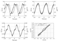
The voltage reader circuit was first tested without the generation of electrosurgical sparks between the test body and the active electrode. These results are presented in the top line of graphics of Figure 5. In the left are presented the waveform of the active electrode v(t) (cross) and the read voltage vv(t) (diamond) without the proposed compensation circuit. It is possible to verify a phase advance in the vv(t) signal in relation to the v(t) signal and some harmonic distortions near the peak region of vv(t) that does not exist in v(t).

In the top line of graphics, on the left, are the active electrode voltage v(t) (cross) and read voltage vv(t) (diamond) without sparks generation and no compensation circuit inclusion. On the left are the voltages v(t) (cross) and vv(t) (diamond) with the compensation circuit inclusion. In the bottom line of graphics, on the left is the voltage v(t) (cross) and vv(t) (diamond) with sparks generation and with the compensation circuit inclusion. In the right is the linear regression statistical analysis of v(t) and vv(t) waveforms presented in the left. The vvest equation of the statistical analysis, the R2 determination factor and the vvest line are presented in this graphic.
After the compensation circuit inclusion, it can be verified, in the right image of the top graphics line of Figure 5, that the phase angle advance is eliminated as well as the harmonic distortions previously present in vv(t) signal.
Tests were also made in the presence of sparks between test body and active electrode. In this case the v(t) signal (cross) presents a few distortions due to the creation and the extinction of the sparks, as can be seen in the peaks region of the waveforms in the left image of the bottom graphics line of Figure 5.
In the same way, the vv(t) signal (diamond) presents some distortions in the peaks region, but due to the small difference between the waveforms in the left image of the bottom graphics in Figure 5, it is important to know how this affects the results. To quantify this distortion, a comparative analysis was performed between the signals, by a linear regression where the y-axis is the read voltage vv(t) and the x-axis is the voltage of the active electrode v(t). From the linear regression, it is possible to find the coefficient of determination R2 that indicates how well the obtained line represents the model under analysis, that is, it can be considered as a quality factor of the reading signal in relation to the signal measured directly in patience circuit. This analysis is presented in the right image of the bottom line of graphics in Figure 5, where is included the “vvest” equation, “vvest” line (bold) and the R2 coefficient.
As can be seen, all points of the readings are close to the “vvest” line even with the distortion at the top of the waveforms shown in the right image of the bottom line of graphics in Figure 5. The equation of the line vvest is presented in the format described in Equation 6, where A is the gain of the read circuit B is the reading offset compared to the active electrode voltage, y is vvest equation an x is v output voltage.
Note that the A gain is not exactly 1/1000. This is due the resistors tolerance, which is 5% for each one. The B offset is about 3 VDC, so it can be despised because this voltage is not enough to cause patient harm. The R2 coefficient indicates that the reading has a very good representation of the active electrode voltage, with near to unit quality factor, indicating that it is suitable for this work proposal.
Similar tests were done with the current read circuit. In the top line of graphics in Figure 6, the results of tests without sparks are presented, where is possible to see, on the left, the output current on Biological Tissue i(t) (cross) and the vi(t) (diamond) voltage comparison, obtained with the shunt resistor without the compensation circuit.
In the top line of graphics, on the left, are the output current i(t) (cross) and read current voltage vi(t) (diamond) without sparks generation and no compensation circuit inclusion. On the left are the current i(t) (cross) and vi(t) (diamond) with the compensation circuit inclusion. In the bottom line of graphics, on the left is the current i(t) (cross) and vi(t) (diamond) with sparks generation and with the compensation circuit inclusion. In the right is the linear regression statistical analysis of i(t) and vi(t) waveforms presented in the left. The viest equation of the statistical analysis, the R2 determination factor and the viest line are presented in this graphic.
Like the voltage read circuit, without the compensation, the reading vi(t) (diamond) has a phase advance in comparison with the biological tissue current i(t) (cross), as well as distortions near to the peak. After the inclusion of the compensation circuit, as showed on the right image of the top line of graphics in Figure 6, the reading vi(t) (diamond) has a very similar format to that shown by the i(t) (cross), including the scales that were amplified in readings without compensation.
With sparks generation, the current waveform presents some distortions, as showed in left image on the bottom line of graphics in Figure 6. The vi(t) voltage (diamond) has a few distinctions from the current i(t) (cross), in special in zero crossing. These differences between waveforms are better visualized in the linear regression image, where there is a separation between points near to zero crossing. The right image on the bottom line of graphics in Figure 6 shows it and include “viest” equation, “viest” line (bold) and R2 coefficient.
In this reading, the quality is somewhat poorer than the voltage reading because the current is more susceptible to harmonic distortions as it is a function of the imposed voltage and the variations of impedances. Even though the R2 quality factor was 96.73%, it is considered an acceptable measure once it does not compromise the calculation of the subsequent circuits, causing the result to go beyond the standard limits. The A coefficient of “viest” equations almost 1 because the resistor has 1 Ω resistance and 5% of tolerance and B coefficient is the offset of the measured signal compared to the output current, which inserts near to 0.1% of error and can be neglected.
Active power calculation
At this point, the reading voltage and current are applied to vv(t) and vi(t) inputs of the analog multiplier presented in Figure 4 and, as output, a voltage signal p(t) representing the instantaneous output power is achieved. To check the signal quality, the reading is compared to an instantaneous output power (pm(t)), mathematically determined by multiplying v(t) voltage and i(t) current. This multiplication was done through Microsoft's Excell software and the readings used were obtained simultaneously with the readings of the multiplier circuit. After the multiplier, the p(t) signal is applied to the integration circuit and an output DC voltage (P) is obtained. Figure 7 presents, on the left, the waveforms of instantaneous output power pm(t), the reading instantaneous output power p(t) and the read output active power proportional signal P.

On the left, the instantaneous output power pm(t) (cross), analog multiplied signal p(t) (diamond) and the proportional active power P (circle). On the right, the linear regression of instantaneous output power pm(t) and p(t) signals presented on the left waveforms.
On the right of Figure 7 is the comparative analysis of pm(t) and p(t) signals. According this linear regression, the quality indicator R2 is higher than 93%, demonstrating that p(t) can be used as a parameter for active power calculation, once its variance is lower than 20%, which is the acceptable error by the IEC standard.
The P waveform, on the left of the Figure 7, presents a DC voltage of 110 mV, proportional to the output active power. The observed ripple in this signal has a peak-to-peak amplitude of 44 mV which represents an instantaneous error of ± 20%. Although this ripple seems to be quite high, it will be ignored because it is consequence of electromagnetic interference (EMI) and can be eliminated by a digital filter, which can be included in the circuit that will use this magnitude to proceed to the indication and control of the active power. In this sense, only the dc level of this signal will be considered in the following analysis.
Considering the dc level of P signal, which is 110 mV, according the 70:1 previously mentioned scale factor, this voltage represents 7.7 W. By proceeding to the calculation of the average value of pm(t), which results in 8.0 W of output active power, a measurement error of 3.75% is achieved, which is a good result due to the measurement error is very lower than the 20% accept by the IEC standard.
In Table 1, some tests are summarized. In these tests were read simultaneously v(t), i(t), p(t) and P signals. With these readings, the instantaneous output power pm(t) is mathematically achieved and the linear regression between it and p(t) were done, which results A and B terms of “Pmest” equation and R2 quality factor.
With the results of pm(t) it was also calculated the active power of the output (Pmath) of each test, by the mathematical determination of the average value of pm(t) for 4 complete periods, that will be considered the reference value for comparisons. This value is compared with P reading to determine the real scale factor (RSF), which makes the value obtained in P to match the Pmath in each test. Using the average value of all RSF, presented in the last line of Table 1, the compensated active power (Pcomp) of each test was find. This is the optimal result of the measurement circuit and the absolute error of this value to the Pmath is presented in Error column. In the spark column, the sparks occurrence of each test is indicated.
In addition, the readings v(t) and i(t) were applied to a knowing ESU active power calculation methodology, presented by Monteiro (Monteiro et al., 2016Monteiro ALR, Grande KC, Faria RA, Schneider B Jr. A simple approach to calculate active power of electrosurgical units. Res Biomed Eng. 2016; 32(1):14-27. http://dx.doi.org/10.1590/2446-4740.0776.
http://dx.doi.org/10.1590/2446-4740.0776...
), and the results are presented in column Papproach. The absolute error between this calculation and the Pcomp are presented in App Error column. In Monteiro methodology, the voltage and current harmonics are determined, offline in silico, by a Fast Fourrier Transformer (FFT). All voltage and current harmonics of same frequency are multiplied, considering the phase angle between them, and the results are summed in a single variable, determining the active power of the system.
As the first result is important to note that the theoretical gains of the reader circuits and power calculations circuits are not accurate. It happens because the passive components applied have a tolerance of 5% and it was not considered in the project, as well as the measurement uncertain due to the probing devices. According to the gain of reader circuits and multiplier, a scale factor of 1:232.5 was expected for P in comparison to Pmath, but the average of A coefficient in the last line of Table 1 shows a lower value of 187.26. For this reason, the scale gain of 70:1 between Pmath and P was not reached either.
To improve the accuracy of the system, a correction factor called RSF was determined and applied to the P value after tests. Without this correction, applying the scale factor of 70:1, the average error found was 11.6% with maximum error of 23.3%. With the application of the average RSF correction factor the average error come into 3.34% with a maximum error of 13.5% in the results of test 21. This maximum error is low enough to attempt the standard 20% requirements.
Interesting is to note that the sparks (and its consequent HF spectrum) do not have a relevant influence in the accuracy of the measurement system once it is fast enough to keep up with voltage and current variations in both cases.
About the offset of the p(t) signal, presented in column B of Table 1, this is a small value and is already included in the calculation of P by the integrator circuit, so it shows that this value does not compromise the reading and measurement errors.
The use of the 2 kHz cutoff frequency and a 4th order Butterworth filter to determine the average power allows any signal above 20 kHz to be correctly calculated, so it is a good solution to proceed the average calculation of ESU signals.
In relation to the comparative of Pcomp and Papproach values, similar errors to Pmath comparative were found. The differences are a consequence of the fact that Monteiro methodology does not use only complete periods of the read signals to perform the active power calculation, unlike the comparison proposed with the calculation of Pmath.
Discussion
The experimental results allow us to verify that the proposed structure can be a good solution to determine the active power of an almost sinusoidal ESU output. This is possible because all systems are projected to operate up to 100 MHz, gauging a great quality to the readings. It was also verified that sparks do not represents a great problem in this solution once que quality factor of the readings still higher than 90% even with sparks between active electrode and test body. In addition, the read circuits layout presents short connections between components and it was allocated as closer as possible to the output of the ESU.
The correlation factor of the reader circuits, before the inclusion of the compensation circuits, were R2 = 0.5052 for the voltage divider and R2 = 0.2148 for the shunt resistor. After the compensation circuit inclusion, these values approached to unit, demonstrating the quality of the solution.
For non-sinusoidal ESU, this solution must be tested but it is to be expected that, as the range of read and calculation circuits is higher than 100 MHz, it will produce very similar results. This bandwidth is a limitation of the system, but it should not be a problem, once the commercial ESU usually works up to 750 kHz for more than fifteen years. The old technology, based on vacuum tubes, frequently operated above 1 MHz, but this technology was discontinuous (Schneider, 2004Schneider B Jr. Estudo teórico-prático de parâmetros técnicos e fisiológicos utilizados em eletrocirurgia, visando a otimização do desenvolvimento e performance de um bisturi eletronico [thesis]. Curitiba: Centro Federal de Educação Tecnológica do Paraná; 2004.).
Another positive point of this system is that it can obtain the active power value in almost real time. In experimental tests with 100% instantaneous interruption of the contact between the active electrode and the test body, the integrator spends less than 400 µs to fit the zero power. This time can be considered a great result because is fast enough to determinate the active power and implement a future control loop to stabilize the output power without significant damages to the biological tissue.
For other operations frequency, the correct RSF factor must be determined, but this works aims to develop the technology that can determine the output active power in real time and according to the standard limits.
Regarding to the IEC 60601-2-2 standard (International…, 2013International Electrotechnical Commission – IEC. IEC 60601-2-2: medical electrical equipment. Part 2-2: particular requirements for the basic safety and essential performance of high frequency surgical equipment and high frequency surgical accessories [internet]. Geneva: IEC; 2013. [cited 2017 May 17]. Available from: http://www.iec.ch/index.htm 2013
http://www.iec.ch/index.htm...
), the measurement error is lower than its limit, which is at most 20%. This is a good indicator that this measurement system can be applied in a control system to regulate the delivered active power and then enabling the equipment to present the output power in Watts.
The system costs about U$ 35.00. This value is very lower than the cost of an isolated current probe for read voltage or current in a measurement commercial system, like an oscilloscope, so that the low-cost objective has been achieved. The low cost is already a reason for the use of wire resistors as shunt. RF resistors are expensive and usually present values higher than 50 Ω, which is not appropriated for this application. Besides, Low Value Resistors (LVR) were tested in the impedance analyzer and they present a capacitive behavior in frequencies near 100 MHz.
About the influence of measurement systems impedance in patient circuit, no significant values are expected once some operational amplifiers were used and then a big impedance was added.
Evaluating the response of the resistors tested in the impedance analyzer, it is possible to argue that both axial ¼ W carbon and SMD 1206 resistors are feasible for this application. In this case the SMDs were used because of their size that allow reduced size layouts.
Finally, it could be seen with the tests and analysis of the results that, with the variation of the RSF, a compensation system will be necessary to correct the measurement errors resulting from the tolerances of the components and measurement uncertainty, and that the ideal correction factor should be raised by means of tests and statistical analysis. But acting in this way the system can guarantee a measurement error that meets the requirements of the standard for electrosurgery equipment.
Acknowledgements
To Texas Instruments and Analog Devices for the samples of used CI’s, to UNIEDU/FUMDES and FITEJ for the financial support and to IFSC for the training license granted.
-
How to cite this article: Dums JF, Schneider B Jr, Badin AA. Low cost system to measure active power in electrosurgical units. Res Biomed Eng. 2017; 33(4):pp-pp. DOI: 10.1590/2446-4740.03217
References
- Bernardi R. Desenvolvimento de um equipamento para estudo de eletrocirurgia com controle de potência ativa [dissertation]. Curitiba: Universidade Tecnológica Federal do Paraná; 2007.
- Dyer SA. Survey of instrumentation and measurement. New York: John Wiley & Sons; 2001.
- Friedrichs DA, Erickson RW, Gilbert J. A new dual current-mode controller improves power regulation in electrosurgical generators. IEEE Trans Biomed Circuits Syst. 2012; 6(1):39-44. PMid:23852743. http://dx.doi.org/10.1109/TBCAS.2011.2159859
» http://dx.doi.org/10.1109/TBCAS.2011.2159859 - Fritz M, Schall H. Electrosurgical generator for the treatment of a biological tissue, method for regulating an output voltage of an electrosurgical generator, and corresponding use of the electrosurgical generator. United States patent US 8920412B2. 2014 Dec 30.
- Institute of Electrical and Electronics Engineers – IEEE. 1459-2010: IEEE standard definition for the measurement of electric power quantities under sinusoidal, nonsinusoidal, balanced, or unbalanced conditions. New York: IEEE; 2010. p. 1-50. http://dx.doi.org/10.1109/IEEESTD.2010.5439063
» http://dx.doi.org/10.1109/IEEESTD.2010.5439063 - International Electrotechnical Commission – IEC. IEC 60601-2-2: medical electrical equipment. Part 2-2: particular requirements for the basic safety and essential performance of high frequency surgical equipment and high frequency surgical accessories [internet]. Geneva: IEC; 2013. [cited 2017 May 17]. Available from: http://www.iec.ch/index.htm 2013
» http://www.iec.ch/index.htm - Jensen S, Maksimovic D. Fast tracking electrosurgical generator using two-rail multiphase buck converter with gan switches. IEEE Trans Power Electron. 2017; 32(1):634-41. http://dx.doi.org/10.1109/TPEL.2016.2524642
» http://dx.doi.org/10.1109/TPEL.2016.2524642 - Ludwig R, Bretchko P. RF circuit design: theory and applications. Upper Saddle River: Prentice-Hall; 2000.
- Monteiro ALR, Grande KC, Faria RA, Schneider B Jr. A simple approach to calculate active power of electrosurgical units. Res Biomed Eng. 2016; 32(1):14-27. http://dx.doi.org/10.1590/2446-4740.0776
» http://dx.doi.org/10.1590/2446-4740.0776 - Pearce JA. Electrosurgery. New York: John Wiley & Sons; 1986.
- Rohde & Schwarz Company. Digital Oscilloscope HMO Series 72x ... 202x [internet]. Melrose: HAMEG; 2011. 48 p. [cited 2017 May 20]. Available from: https://www.utwente.nl/tnw/slt/doc/apparatuur/oscilloscopen/hameg-man-en-hmo72x-202x.pdf
» https://www.utwente.nl/tnw/slt/doc/apparatuur/oscilloscopen/hameg-man-en-hmo72x-202x.pdf - Schmitt OH, Tucker RD, Sievert CEJ Jr, Silvis SE. A miniature current probe for measuring electrosurgical currents. Med Instrum. 1983; 17(4):276-7. PMid:6633320.
- Schneider B Jr. Estudo teórico-prático de parâmetros técnicos e fisiológicos utilizados em eletrocirurgia, visando a otimização do desenvolvimento e performance de um bisturi eletronico [thesis]. Curitiba: Centro Federal de Educação Tecnológica do Paraná; 2004.
- Schneider B Jr, Abatti PJ. Desenvolvimento de um equipamento eletrocirúrgico com saída não chaveada. Rev Bras Eng Bioméd. 2005; 21:15-24.
- Schneider B Jr, Abatti PJ. Electrical characteristics of the sparks produced by electrosurgical devices. IEEE Trans Biomed Eng. 2008; 55(2):589-93. PMid:18269994. http://dx.doi.org/10.1109/TBME.2007.903525
» http://dx.doi.org/10.1109/TBME.2007.903525 - Smith KC, Sedra AS. Microeletrônica. 5th ed. São Paulo: Pearson Prentice Hall; 2007.
- Tucker RD, Stasz PS, Kramolowsky EV. A simple and inexpensive method for measuring electrosurgical variables. Biomed Instrum Technol. 1989; 23(1):54-7. PMid:2924053.
- Visser H, Fastenmeier K, Mausberg R, Lohr G. Measurement of physical parameters in HF surgical techniques in dentistry. ZWR. 1991; 100:219-23.
- Wurzer H, Maeckel R, Lademann J, Audring H, Liess HD. A spark counter as a control unit of a radio frequency surgery device. IEEE Trans Biomed Eng. 1997; 44(9):831-8. PMid:9282475. http://dx.doi.org/10.1109/10.623052
» http://dx.doi.org/10.1109/10.623052 - Zhou Y, Li D, Xu W, Song C. A new parameter measurement system for electrosurgery output. Sheng Wu Yi Xue Gong Cheng Xue Za Zhi. 2014; 31(2):421-5. PMid:25039153.
Publication Dates
-
Publication in this collection
09 Nov 2017 -
Date of issue
Oct-Dec 2017
History
-
Received
21 June 2017 -
Accepted
14 Oct 2017


