Abstract
In a polymer electrolyte fuel cell (PEFC) startup below freezing point, it is known that shutdown occurs due to the produced water freezing in the cell. The authors' research group has been conducting experimental studies on the freezing behaviors and mechanism. At −20°C, the generated water freezes at the moment when the water comes out into the catalyst layer (CL) pores, and at −10°C, the generated water moves inside the fuel cell in the supercooled state and freezes (1)-(2). It was also reported that the ice frozen at the micro porous layer (MPL) and CL interface absorbs generated water through the ionomer in the CL (3). This study conducted both model analyses to evaluate the water content in membrane and experimental investigations to confirm the cold start characteristics with temperature rise.
A single cell with an active area of 25 cm2 (5 cm × 5 cm) was used in this study. As shown in Figure 1, heaters and heat insulating plates were inserted between the current collectors and the end plates to simulate the adiabatic condition by controlling the cell temperature. Heat release from the sides of in-plane direction was suppressed by winding a heat insulating material (not shown in Figure 1). After a preconditioning process to enhance the performance of a MEA, the initial conditions of water in the cell were carefully controlled by the procedure described in Ref. 1. Then the cell and the chamber were cooled to a target temperature, and cell operation was started. Dry hydrogen and dry air were supplied to anode and cathode.
In the model analysis, we considered three phenomena related to water generation and water transport: water generation in cathode CL by the reaction, back diffusion from the CL to membrane, and electro-osmosis from membrane to the CL. Two types of loading current method, ramp loading and 2 step loading, were applied. Figure 2 shows changes in the resistance overvoltage calculated from the evaluated water content in membrane during cold startup at −30°C. In the ramp loading, the applied current density was increased linearly for initial 30 sec to 0.07A/cm2; in the 2 step loading the current densities were set constant, 0.04A/cm2, for initial 30 sec followed by 0.07A/cm2. Here, this model was developed based on the experimental results of isothermal cold startup at −30°C. In the experiments, shutdown due to dry-out occurred in the ramp loading while the startup succeeded in the 2 step loading. In Figure 2, the maximum resistance overvoltage in the 2 step loading is lower, showing advantage in early startup without dry-out. Next, we conducted the cold startup with adiabatic temperature rise at −30°C, as shown in Figure 3. The 2 step loading was applied, and the heaters were used to simulate adiabatic temperature rise due to the heat of reaction during cold startup in the cell at central part in a stack loaded on automobile. In early cold startup, shutdown does not occur, and the cell resistance can be decreased by produced water due to the reaction. Then, cell temperature reaches 0°C at 273 sec before ice formation in the cell perfectly hinder the supply of oxygen. The more appropriate startup method and water transport phenomena in the cell are further investigated in this study.
Reference
(1) Y. Tabe, et al. , J. Power Sources 208 (2012), 366.
(2) Y. Tabe, et al. , J. Electrochem. Soc. 163 (10) (2016), F1139.
(3) N. Wakatake, et al. , ECS Trans. 75 (14) (2016), 623.
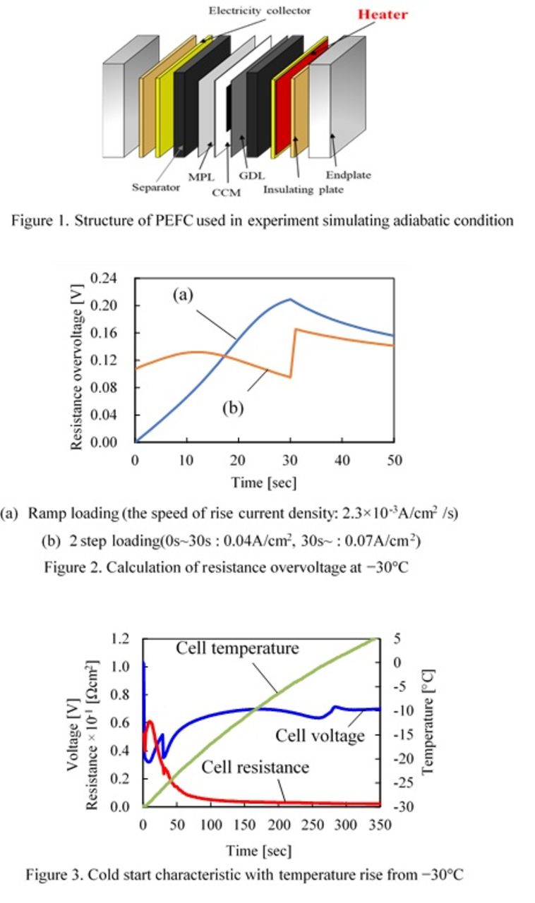
Figure 1