Abstract
Effect of weak carbide formers, Mo, Mn and Si, on intergranular corrosion (IGC) of low-Cr ferritic stainless steel is analyzed after IGC test using TEM and three dimensional atom probe. The co-addition of Mo, Mn and Si to low-Cr ferritic stainless steel effectively prevents IGC by forming along grain boundaries CMn4MoSi intermetallic compounds, which act not only as carbon trap sites but also as diffusion barrier against solute Cr diffusion toward grain boundaries. The low solubility of Cr in the CMn4MoSi intermetallic compound results in replenishing Cr in the Cr-depleted area.
Export citation and abstract BibTeX RIS

This is an open access article distributed under the terms of the Creative Commons Attribution Non-Commercial No Derivatives 4.0 License (CC BY-NC-ND, http://creativecommons.org/licenses/by-nc-nd/4.0/), which permits non-commercial reuse, distribution, and reproduction in any medium, provided the original work is not changed in any way and is properly cited. For permission for commercial reuse, please email: oa@electrochem.org.
The low-chromium (Cr) ferritic stainless steels (FSSs) are widely used as an economical structural material in moderate corrosive environments because they have high strength and good corrosion resistance. The low-Cr FSSs contain Cr content in a range of 11 to 13 wt% and they are used for automotive exhaust system, chemical processing equipment, furnace parts, heat exchangers, recuperates, oil burner parts and storage vessels.1,2 Welding is an inevitable manufacturing process to make the structural components with low-Cr FSS. Since fusion welding such as gas metal arc welding (GMAW) is a common practice for low-Cr FSS, during service, it often results in a serious industrial problem of sensitization or intergranular corrosion (IGC).2–4 Sensitization occurs quite easily in FSS, which has body centred cubic (BCC) structure, because of its low solubility of interstitial elements of carbon (C) and nitrogen (N).5 In FSS, sensitization may occur as fast as less than 0.01 s because of high diffusivity of C and N in BCC structure.6 Therefore, prevention of sensitization of low-Cr FSS requires careful alloy design with a clear understanding on the IGC mechanism.
IGC of stainless steel is known to occur due to electrochemical potential difference between the matrix and Cr depleted zone in the vicinity of grain boundary area. According to the conventional IGC mechanism,6–8 Cr depletion and consequent IGC are induced by formation of Cr-carbide and/or Cr-carbonitride along grain boundaries. Based on the conventional IGC mechanism, the general commercial recommendation to prevent IGC of stainless steel is reduction in the content of C and N, and addition of strong carbide former as a stabilizer such as titanium (Ti) and niobium (Nb). For austenitic stainless steels, it is recommended to reduce the C content to less than 0.03 wt%, wheareas for ferritic stainless steels, to reduce the total amount of C and N less than 0.01 wt%.6,8 The amount of stabilizer to prevent IGC varies depending on the alloy composition and welding process. To recommend the proper amount of stabilizer, the stabilization ratio (SR) is commonly used, where SR is defined as the ratio of the total amount of Ti and Nb to total amount of C and N. For low-Cr FSS, the technical standards of ASM and ASTM recommend various amount of stabilizer equivalent to SR values of 5 to 6.8,9 Niekerk et al. have suggested SR value more than 6 with specific heat input level,10 whereas Fritz and Franson have recommended it be more than 8.3 However, most IGC tests on 409 FSS designed with the SR value less than 12 have shown IGC attack when welded with fusion weld such as GMAW.2,3,10,11 Therefore, for IGC prevention of type 409 FSS, Hisamatsu and Ogawa have suggested that the SR value should be more than 20.12 For prevention of IGC in low-Cr FSS, the SR value has been increased even over 20, but the problem has not been solved. Our previous studies have shown that IGC occurs in all low-Cr FSSs containing Cr in a range of 11–13 wt% even with the SR value in a rage of 20–27.13,14 Increase in the Cr content improves the IGC resistance to a certain level, but does not prevent it completely. The results mentioned above strongly suggest that the conventional IGC mechanism may not operate in the stabilized low-Cr FSS and thus addition of strong carbide former as stabilizer may not be a solution for IGC prevention.
Most studies on IGC of stainless steel have shown a high Cr peak at the grain boundaries analyzed by energy dispersive spectroscopy (EDS) and simply assumed that as grain boundary precipitation of Cr-carbide.2,10,11 Unfortunately, no one has ever raised the question on Cr segregation other than by formation of Cr-carbide. To understand clearly the IGC mechanism occurring in stabilized low-Cr FSS, we have studied carefully the grain boundary segregation behavior with atomic level analysis by using a 3-dimensional atom probe (3DAP), and it has been revealed that in the stabilized 409L FSS, Cr depletion occurs due to segregation of the solute Cr, but not due to formation of Cr-carbide or Cr-carbonitride.15,16 Li et al. also have investigated the sensitization phenomena of 15 wt% Cr FSS stabilized with 0.48 wt% Nb, and no Cr compounds are formed in the stainless steel even though the grain boundary of FSS is sensitized.17 Our additional studies on different sets of both stabilized ferritic and austenitic stainless steels with various SR values have revealed clearly that the IGC mechanism occurring in stabilized stainless steels is different from the conventional IGC mechanism.18,19 On the basis of such findings, a new IGC mechanism has been proposed. This new IGC mechanism is that IGC occurring in the stabilized stainless steel is induced by Cr depletion due to segregation of solute Cr atoms near grain boundary carbides such as TiC, (Ti,Nb)C, or NbC, but not due to formation of Cr-carbide.19 This newly proposed IGC mechanism is totally different from the conventional IGC mechanism. As a result, different IGC prevention methods other than adding the strong carbide former as stabilizer should be introduced.
If the newly proposed IGC mechanism is valid for low-Cr FSS, since Cr-depletion is due to segregation of solute Cr atoms, any mechanism to prevent diffusion of solute Cr atoms toward grain boundary should be the key concept for prevention of Cr-depletion. Therefore, the new alloy design concept for IGC prevention should include the following issues:
- (1)Formation of a compound which can become an effective barrier against diffusion of solute Cr atoms toward grain boundary,
- (2)Trapping C in the compound to avoid formation of Cr-carbide, and
- (3)Amount of elements adding to prevent IGC should be small enough not to harm welding and forming.
Figure 1 shows the stability diagram of various carbides.20 The carbide forming elements may be classified into two groups. One group is the elements having higher carbon affinity than Cr and the other group is the elements having lower carbon affinity than Cr. The former is called as the "strong carbide former (SCF)" and the latter will be called henceforth as the "weak carbide former (WCF)." SCFs such as Ti and Nb are conventionally used as stabilizing element for IGC prevention. However, these elements do not easily form any compound other than carbide in stainless steel. In contrast to the conventional alloy design concept, the weak carbide formers such as Mn, Mo and Si were chosen for this study since many studies have reported that Mo and Mn usually form intermetallic compounds along grain boundaries21,22 and Si usually segregates along grain boundaries during heat-treatment.23 Formation of an intermetallic compound, composed of Mo, Mn and Si, along grain boundary can be expected with consequent effect on diffusion of solute Cr atoms.
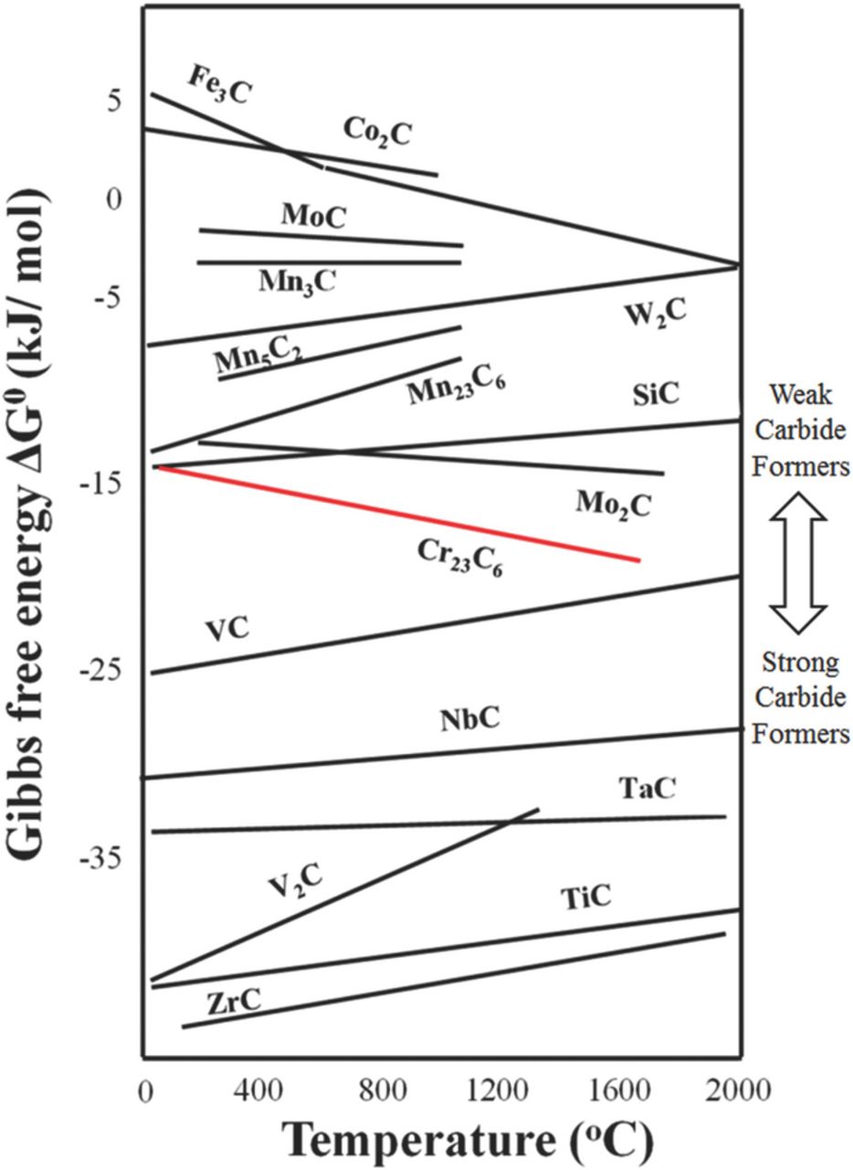
Figure 1. Ellingham diagram of carbides formation.20
In this study, two different groups of experimental alloys are prepared with addition of Mo, Mn and Si to low-Cr FSS. The first group is designed to study the effect of each alloying element on IGC behavior and to determine the optimum composition for IGC prevention, and the second group is to analyze the IGC prevention mechanism by addition of WCFs. The IGC behavior is evaluated by both the chemical immersion test and the double-loop electrochemical potentiokinetic reactivation (DL-EPR) test. Segregation and depletion of the alloying elements are examined by a number of microstructural analyses including SEM and TEM. 3DAP is employed for nano-scale analysis on grain boundary segregation.
Experimental
Test materials and specimen preparation
Table I lists the chemical composition of 11 experimental alloys in the first group. The specimen numbers starting with SCF means that the alloys are prepared with addition of the strong carbide former and those starting with WCF means that the alloys are prepared with addition of the weak carbide formers. The main purpose of this alloy group was to determine the range of amount of each alloying element which can prevent IGC, but does not impart any negative effect on the following welding and forming processes. SCF-1 and SCF-2 were prepared with addition of Ti as stabilizer with SR being 10.8 and 14.5, respectively. However, SCF-1 has higher C content than SCF-2. All the alloys prepared with addition of WCFs were designed to observe the effect of each element on IGC by fixing the amount of either one or two out of Mn, Mo and Si, and the levels of C and N content are controlled to have less than 100 ppm or 0.01 wt%.
Table I. Chemical composition of experimental alloys in the first group (unit: wt%).
| Specimen | C | N | Cr | Ti | Mn | Mo | Si |
|---|---|---|---|---|---|---|---|
| SCF-1 | 0.0100 | 0.0067 | 10.98 | 0.18 | 0.27 | <0.01 | 0.5 |
| SCF-2 | 0.0070 | 0.0068 | 11.26 | 0.20 | 0.20 | <0.01 | 0.5 |
| WCF-1 | 0.0089 | 0.0084 | 10.98 | 0.18 | 0.27 | <0.01 | 0.6 |
| WCF-2 | 0.0083 | 0.0082 | 10.98 | 0.18 | 0.27 | <0.01 | 0.7 |
| WCF-3 | 0.0061 | 0.0056 | 10.54 | <0.01 | 0.37 | 0.1 | 0.3 |
| WCF-4 | 0.0040 | 0.0057 | 11.22 | <0.01 | 0.22 | 0.1 | 0.8 |
| WCF-5 | 0.0060 | 0.0069 | 11.15 | 0.05 | 0.22 | 0.05 | 0.9 |
| WCF-6 | 0.0058 | 0.0063 | 10.45 | <0.01 | 0.37 | 0.2 | 0.4 |
| WCF-7 | 0.0061 | 0.0053 | 10.20 | <0.01 | 0.37 | 0.1 | 0.6 |
| WCF-8 | 0.0081 | 0.0047 | 10.98 | 0.18 | 0.27 | 0.1 | 0.7 |
| WCF-9 | 0.0067 | 0.0064 | 11.12 | 0.19 | 0.38 | 0.1 | 0.8 |
Table II lists the chemical composition of 6 experimental alloys in the second group. SCF-11 and SCF-12 are prepared with addition of Ti and Nb as stabilizer with SR being 21 and 29, respectively. 4 experimental alloys with WCFs were prepared with different amount of Mo, Mn and Si to figure out adequate alloying composition to prevent IGC of low-Cr FSS and to investigate the IGC prevention mechanism by addition of WCF elements. From the preliminary study with the experimental alloys in the first group, the optimum composition of WCF-14 was to have 0.12 wt% Mo, 0.61 wt% Si and 0.37 wt% Mn. The alloy composition of WCF-14 meets the new alloy design concept mentioned earlier. On the other hand, other WCF alloys were prepared with insufficient amounts of one element out of Mo, Mn, and Si. WCF-11 had an insufficient amount of Mo, WCF-12 had an insufficient amount of Si, and WCF-13 had an insufficient amount of Mn.
Table II. Chemical composition of experimental alloys in the second group (unit: wt%).
| Specimen | C | N | Cr | Nb | Ti | Mo | Mn | Si |
|---|---|---|---|---|---|---|---|---|
| SCF-11 | 0.007 | 0.007 | 11.03 | 0.15 | 0.14 | <0.01 | 0.18 | 0.40 |
| SCF-12 | 0.006 | 0.005 | 11.75 | 0.15 | 0.17 | <0.01 | 0.21 | 0.51 |
| WCF-11 | 0.008 | 0.010 | 11.12 | <0.01 | <0.01 | <0.01 | 0.39 | 0.62 |
| WCF-12 | 0.006 | 0.006 | 10.54 | <0.01 | <0.01 | 0.11 | 0.37 | 0.28 |
| WCF-13 | 0.004 | 0.006 | 11.23 | <0.01 | <0.01 | 0.12 | 0.22 | 0.75 |
| WCF-14 | 0.006 | 0.005 | 10.23 | <0.01 | <0.01 | 0.12 | 0.37 | 0.61 |
The experimental alloys were produced by vacuum arc melting and hot rolled to 2.0 mm thick sheet in laboratory. The specimens were solution treated at 1300°C for 10 min, quenched by water, and then aged at 500°C for 2 h.
Intergranular corrosion test
Intergranular corrosion resistance was examined by the chemical corrosion test using modified Strauss test solution (0.5% H2SO4 + 6% CuSO4) introduced by Devine for low-Cr FSS (10–13 wt% Cr).24,25 The concentration of H2SO4 in this solution was much lower than 16% of ASTM A262 and A763 to prevent heavy general corrosion of low-Cr FSS. Rectangular test coupons (12 × 12 × 1.2 mm) grinded with abrasive paper up to P2000 were immersed in the boiling solution of 300 ml and contacted electrochemically with copper balls in the solution to induce a galvanic effect on the specimen. After 20 h of immersion, the microscopic observation on the specimen surface was conducted for IGC attack.
Double-loop electrochemical potentiokinetic reactivation (DL-EPR) test
The DL-EPR test is a well established method to evaluate IGC of the low-Cr FSS.2,4,13,26–28 The DL-EPR test was conducted in 0.5% H2SO4 solution with 0.0013 wt% KSCN at 30°C after grinding the surface of the specimens with abrasive paper P2000. The specimen was anodically polarized from the corrosion potential to 800 mVSCE with the scan rate of 1.67 mV/s. In this polarization, the active dissolution occurs, and then a passive layer forms on the entire surface. At 800 mVSCE, the polarization was reversed with the same scan rate, and the test was finished at the corrosion potential from which the polarization scan was initially started. The reverse scan induced the breakdown of the passive layer in the Cr depleted zone. The anodic loop was larger than the reverse loop because the entire surface of the specimen was activated just before reaching the primary passive potential. However, during the reverse scan, the small reverse loop was measured because most surface area was covered with the passive layer, except for the activated area of the Cr depleted zone around grain boundaries. The maximum activation current peak (Ia) and the maximum reactivation current peak (Ir) were determined from the polarization curves. The degree of sensitization (DOS) of the specimens was determined as the ratio of Ir/Ia. After the DL-EPR test, the microstructure of the specimens was examined to evaluate the susceptibility of IGC and grain boundary morphology was classified as either step (no sensitization), dual (a little sensitization), or ditch (significant sensitization).26,29
Metallographic observation
Metallographic observation was performed with various techniques. Morphology of grain boundaries was observed with SEM (JEOL JSM-7401F). Analysis on the intermetallic compounds was carried out by using TEM (JEOL JEM-2200FS with Image Cs-corrector) with electron energy loss spectroscope (EELS). A TEM sample was prepared with a carbon extraction replica method. The nanoscale analysis on grain boundary was performed with Cameca LA-WATAPTM laser-assisted three-dimensional atom probe (3DAP), which was particularly useful for analyzing the elemental distribution with near-atomic resolution.30 Samples for 3DAP analysis were prepared with a focused ion beam (FIB) milling process.
Results and Discussion
Intergranular corrosion test
Figure 2 presents the surface appearances of 11 experimental alloys in the first group after the modified Strauss IGC test. SCF-1 and SCF-2 are severely damaged even though they are stabilized with Ti. The degree of damage is more severe in SCF-1 than in SCF-2 since SCF-1 has more C content than SCF-2. The surface appearances of WCF-1, WCF-2 and WCF-3 indicate that addition of Mn, Si and Mo definitely improves IGC resistance. The surface appearances of WCF-4 and WCF-5 also suggest that the critical Mn content is important to secure the IGC prevention even though enough amount of Mo and Si is added. Through a careful examination on the IGC test results of the experimental alloys, a number of alloys such as WCF-6, WCF-7, WCF-8 and WCF-9 were prepared, and all of them show no sign of IGC attack. The IGC test on the first group of the experimental alloys suggests the minimum amount of WCFs for optimum alloy composition. For IGC prevention of low-Cr FSS, the critical amount of Mn, Mo and Si seems to be 0.35 wt%, 0.1 wt% and 0.6 wt%, respectively. On the basis of the IGC test result of the first experimental alloy group, the second alloy group was designed as listed in Table II to examine the IGC prevention mechanism by addition of WCFs.
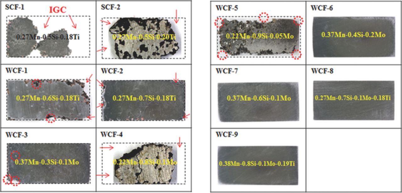
Figure 2. The surface appearance of experimental alloys in the first group after the modified Strauss IGC test.
Figure 3 presents the grain boundary morphologies of the specimens after the modified Strauss IGC test. The evidence of IGC such as grain dropout (marked as A in Figure 3) and dissolution of grain boundary are observed in both SCF-11 and SCF-12. Both alloys stabilized with strong carbide formers are sensitized even though the SR value of SCF-11 (SR = 21) and SCF-12 (SR = 29) are higher than the recommended SR value (SR = 20).12 However, WCF-14, which contains 0.12 wt% Mo, 0.37 wt% Mn and 0.61 wt% Si, is not sensitized at all, and it suggests that the co-addition of Mo, Mn and Si to low-Cr FSS is effective to suppress the sensitization and IGC. On the other hand, grain dropout was observed in WCF-11, which indicates that addition of only Mn and Si without Mo cannot prevent IGC. Though Mo was added more than 0.1 wt%, a lack of Si as in WCF-12 or a lack of Mn as in WCF-13 also induces IGC of low-Cr FSS. This result reveals that IGC of low-Cr FSS can be effectively prevented if the proper amounts of Mo, Mn, and Si are added.
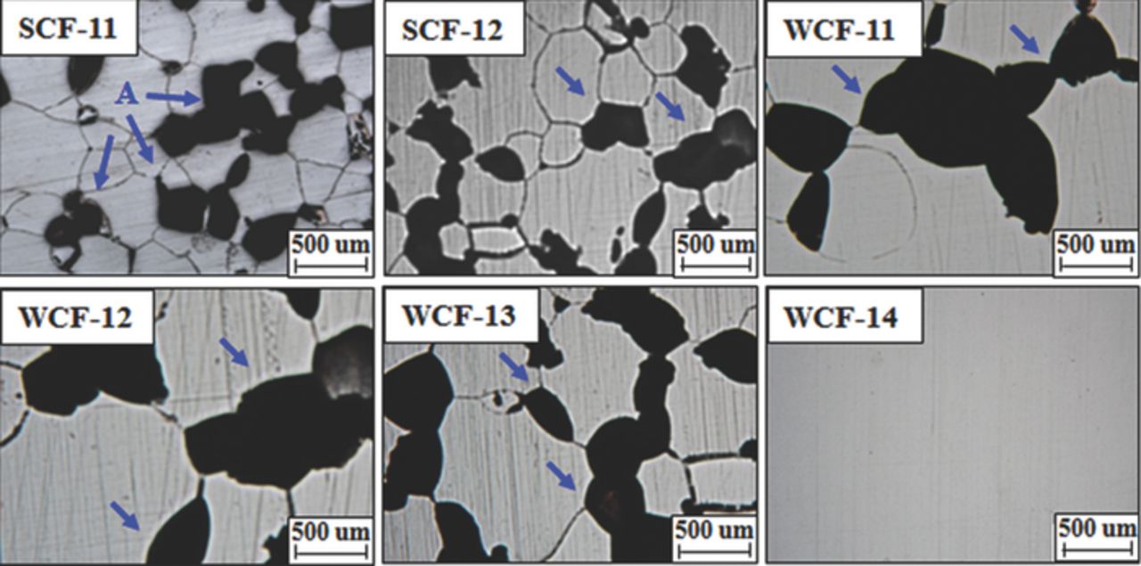
Figure 3. The grain boundary morphology of experimental alloys after the modified Strauss IGC test.
DL-EPR test
DL-EPR was conducted as an additional, quantitative measure of the sensitization level. Figure 4 compares the DL-EPR test result of the conventionally stabilized specimens, SCF-11 and SCF-12, with that of WCF-14 alloyed with weak carbide former. From the DL-EPR test results, the values of the peak reactivation current (Ir) and peak anodic current (Ia) were measured and DOS (Ir:Ia) were calculated as listed in Table III.4,13,31 In the case of low-Cr FSS, previous studies suggest that IGC of low-Cr FSS can be prevented when DOS value is lower than 0.03.13,19 It was revealed that DOS values of SCF-11 and SCF-12 were higher than this criterion, whereas DOS value of WCF-14 was lower than this criterion. As shown in Figure 5, the grain boundary morphology of SCF-11 and SCF-12 shows a ditch structure along the grain boundary after DL-EPR test, suggesting that the grain boundaries of both SCF-11 and SCF-12 were sensitized. On the other hand, the DOS value of WCF-14 was lower than 0.03, and step structure was clearly observed from the grain boundary after DL-EPR test. The results of DL-EPR are in good agreement with the previous result of the modified Strauss test and also suggests that the co-addition of Mo, Mn, and Si in WCF-14 was effective to prevent grain boundary sensitization.
Table III. Degree of sensitization of steels measured by DL-EPR test.
| Specimen | Ia (A cm−2) | Ir (A cm−2) | DOS * |
|---|---|---|---|
| SCF-11 | 0.012 | 0.00048 | 0.040 |
| SCF-12 | 0.011 | 0.00044 | 0.040 |
| WCF-14 | 0.011 | 0.00025 | 0.023 |
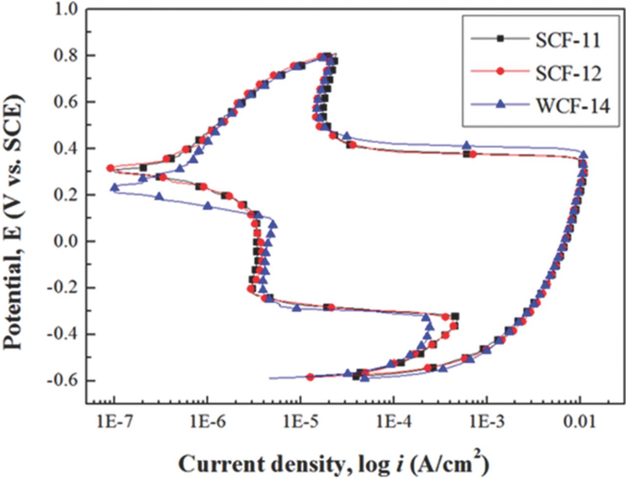
Figure 4. DL-EPR test result of low-Cr ferritic stainless steel.
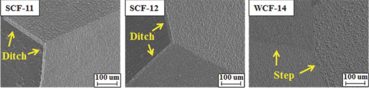
Figure 5. Grain boundary morphology of steels after DL-EPR test.
Characterization of intermetallic compounds
Figure 6 presents SEM characterization along grain boundary of WCF-14, and it indicates that most of grain boundary area is occupied by 200–300 nm size of intermetallic compounds. However, no Cr compound, including Cr-carbide or Cr-carbonitride, is observed near the grain boundary in WCF-14. The co-addition of Mo, Mn and Si prevents grain boundary sensitization and consequent IGC of WCF-14 by formation of blocky intermetallic compound along grain boundary. To investigate the chemical composition and crystal structure of the intermetallic compounds along grain boundaries, TEM characterization was performed on WCF-14 specimen. Figure 7 presents a bright field image with EELS mapping of the WCF-14 specimen prepared by the carbon replica method and its electron diffraction pattern analysis result. From EELS analysis, it is revealed that the intermetallic compound consisted of C, Mo, Mn, and Si as shown in Figure 7(a). Electron diffraction pattern analysis on this intermetallic compound identifies it as CMn4MoSi, as shown in Figure 7(b).32 Formation of this CMn4MoSi intermetallic compound requires the proper amount of Mo, Mn, and Si because WCF-11 (insufficient Mo content), WCF-12 (insufficient Si content), and WCF-13 (insufficient Mn content) do not form sufficient amount of CMn4MoSi intermetallic compound to prevent IGC. Only WCF-14 has a sufficient amount of Mo, Mn, and Si and it promotes the formation of CMn4MoSi intermetallic compound along grain boundaries to suppress effectively the sensitization of FSS.
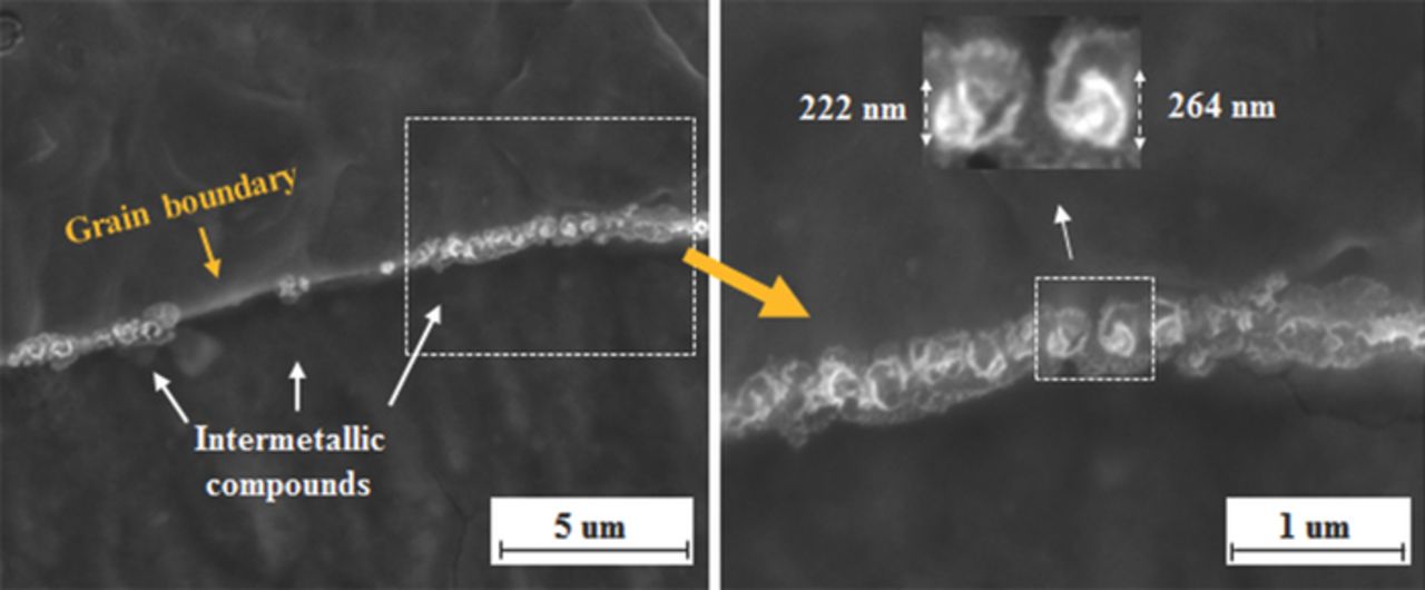
Figure 6. SEM characterization on intermetallic compounds formed along grain boundary of WCF-14.
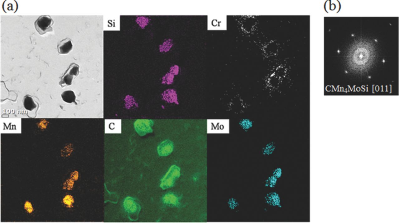
Figure 7. TEM characterization with EELS mapping and diffraction pattern analysis on intermetallic compounds formed in WCF-14.
The intermetallic compound CMn4MoSi formed along grain boundary of FSS can block the diffusion of C and Cr toward the grain boundary during heat-treatment. Moreover, it is very interesting to observe from Figure 7(a) that Cr is segregated around the intermetallic compounds. It seems that the solubility of Cr in CMn4MoSi is low enough to expel Cr from it. Then, Cr has little chance to react with C because C is already consumed to form CMn4MoSi intermetallic compound. This means that formation of CMn4MoSi intermetallic compound along grain boundaries helps to segregate the solute Cr around CMn4MoSi intermetallic compound, so that Cr can be replenished along the grain boundary instead of Cr being depleted.
3DAP analysis
To investigate atomic segregation behavior in the vicinity of grain boundaries, 3DAP characterization of WCF-13 and WCF-14 was performed and the results are compared with that of SCF-11. The concentration profile of alloying elements along the grain boundary of SCF-11 was investigated in our previous study and is shown in Figure 8.16 Figure 8(b) indicates that Cr atoms were extensively segregated up to 35.8 at.% on the grain boundary and consequent Cr depletion in the vicinity of the Cr segregation zone. The lowest Cr concentration of the depletion zone near the grain boundary of SCF-11 was only 5.3 at.%, which suggests that the grain boundaries of SCF-11 were sensitized. Figure 9 presents the concentration profile along the grain boundary of WCF-13, which contains sufficient amounts of Mo and Si, but an insufficient amount of Mn. The 3DAP elemental maps of WCF-13 shown in Figure 9(a) indicate that segregation of Cr, C, Mo, Mn, and Si occurs along grain boundaries. Figure 9(b) shows the concentration profile across the grain boundary of WCF-13, where Cr atoms were segregated up to 23.0 at.% and Cr depletion was down to 7.8 at.%. It is interesting that though Cr segregation occurred in both SCF-11 and WCF-13, the concentration of Cr (23.0 at.%) at the grain boundary of WCF-13 was much lower than that (35.8 at.%) of SCF-11.
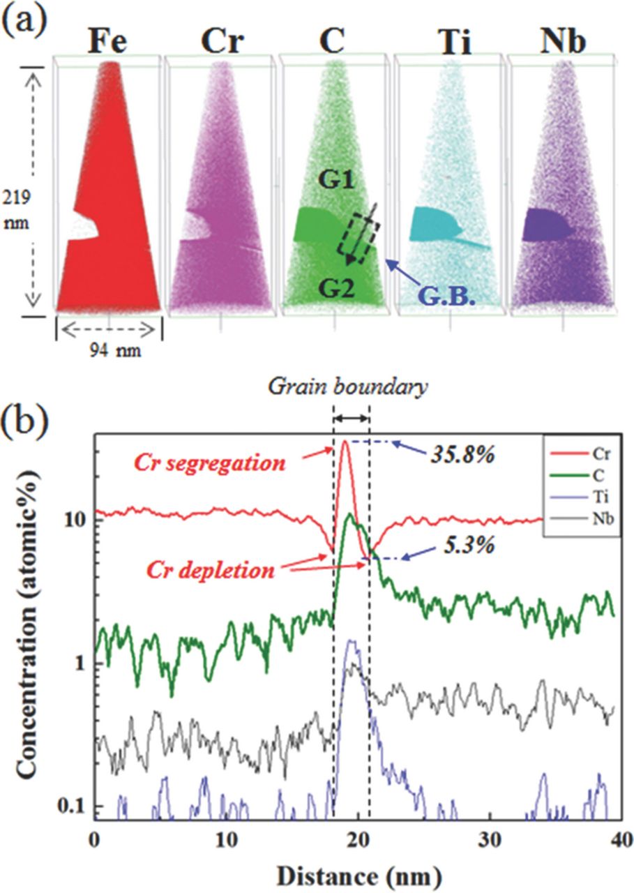
Figure 8. 3DAP characterization along grain boundary of SCF-11 from our previous study.16 (a) 3DAP element maps, (b) concentration profile across the grain boundary.
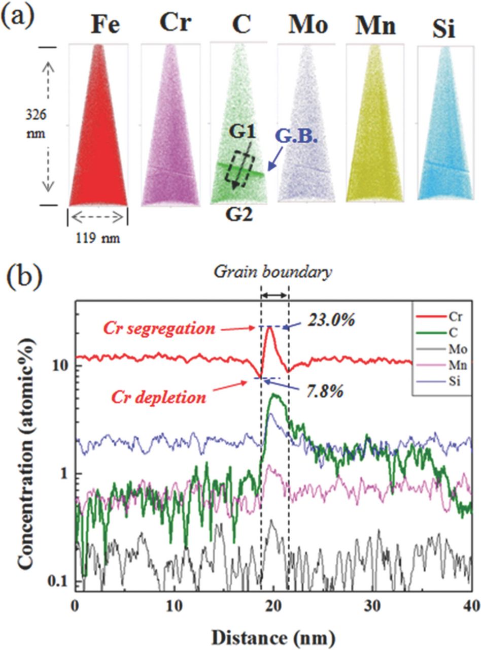
Figure 9. 3DAP characterization along grain boundary of WCF-13. (a) 3DAP element maps, (b) concentration profile across the grain boundary.
WCF-14, which contains a sufficient amount of all three elements of Mo, Si, and Mn, shows a totally different Cr profile near the grain boundary when compared with that of SCF-11. As shown in Figure 10, the highest amount of segregated Cr along the grain boundary of WCF-14 was only 18.2 at.%, which was much lower than those of SCF-11 and WCF-13, and there was virtually no Cr depletion near the grain boundaries because Cr content in the depleted area was only 9.9 at.%.
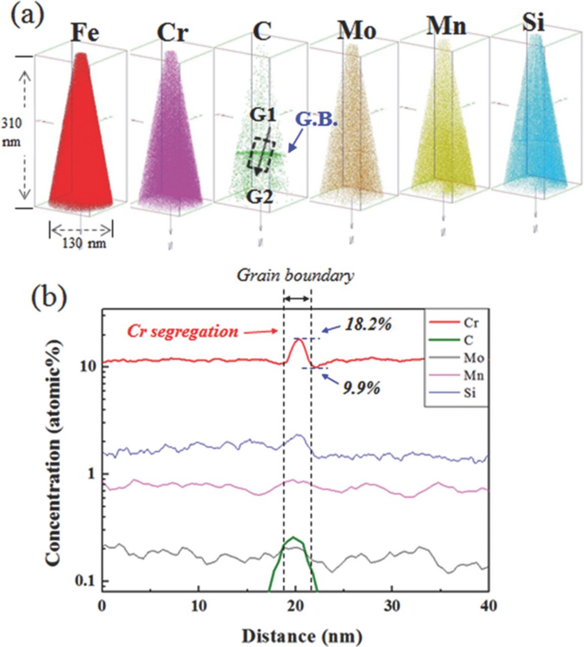
Figure 10. 3DAP characterization along grain boundary of WCF-14. (a) 3DAP element maps, (b) concentration profile across the grain boundary.
The difference in the Cr profile along grain boundary of SCF-11, WCF-13 and WCF-14 is closely related with the C profile. During the heat-treatment and cooling or aging, solute C diffuses first to grain boundaries due to its much higher diffusivity than those of other elements. According to the conventional IGC mechanism, segregation of Cr is induced and fixed by the formation of Cr carbide. However, in case of the stabilized low-Cr FSS, Kim et al. have reported that, although Cr carbide is not formed, segregated C induces saturation of the solute Cr atoms along grain boundary and it consequently promotes sensitization.19 During aging, all the elements in the matrix tend to diffuse toward grain boundaries. Carbon diffuses first to the grain boundaries because of its much higher diffusivity than the other elements. Because of chemical affinity with C, both Cr and Ti diffuse to grain boundaries. Because Ti has stronger carbon affinity than Cr, Ti forms TiC preferentially. Cr cannot form Cr-carbide because no free C is available and thus solute Cr atoms are segregated near grain boundary. As the aging time increases, while precipitation of TiC or NbC progresses, back diffusion of these segregated Cr is insufficient, and thus grain boundaries of FSS is sensitized.16 Therefore, to avoid segregation of Cr and consequent IGC of low-Cr FSS, segregation of C along grain boundaries should be suppressed.
From the 3DAP results, the relationship between IGC and atomic distribution of Cr and C along grain boundary can be obtained and the results are listed in Table IV. After the aging treatment, C atoms in SCF-11 are segregated along grain boundaries up to 11.2 at.%, and they induce segregation of Cr up to 35.8 at.%. In contrast, when WCF elements of Mo, Mn, and Si are added to low-Cr FSS, the concentration of C along grain boundaries significantly decreases. In the case of WCF-13 in which even though an insufficient amount of Mn was added, C atoms were segregated along grain boundaries to 5.5 at.% and it was lower than that of SCF-11. As the segregation of C along grain boundaries was reduced, that of Cr was also decreased to 23.0 at.%, and concentration of Cr in the Cr depleted zone was higher in WCF-13 (7.8 at.% Cr) than in SCF-11 (5.3 at.% Cr). In the case of WCF-14, when a sufficient amount of Mo, Mn, and Si was added to FSS, C atoms were segregated only to 0.26 at.%, which was much lower than that in both SCF-11 and WCF-13. Because 3DAP analysis was conducted in the nano-scale range, for proper analysis, extreme care and expertise was required for the sample preparation. Therefore, the quantitative analysis on C distribution along the grain boundaries should be precisely investigated with different sets of specimens in further research. However, both WCF-13 and WCF-14 with co-addition of Mo, Mn, and Si show a similar tendency to suppress C segregation along the grain boundaries, and this phenomenon is promoted as the concentration of Mo, Mn, and Si increases (SCF-11 < WCF-13 < WCF-14). Therefore, comparison of 3DAP analysis data of alloys with strong carbide former (SCF-11) and with weak carbide former (WCF-13 and WCF-14) suggests that the co-addition of weak carbide formers (Mo, Mn, and Si) is effective to suppress segregation of C along the grain boundaries in low-Cr ferritic stainless steel and seems to be related to the formation of CMn4MoSi intermetallic compound. Because the C concentration profile by 3DAP was measured within a limited area (∼40 nm) near the grain boundaries, the scan area of 3DAP for WCF-14 shown in Figure 10 is significantly smaller than the size of the intermetallic compound (∼250 nm as shown in Fig. 6) formed along the grain boundary. Therefore, the C profile near the grain boundaries of WCF-14 does not represent C concentration in the matrix, but it was influenced by formation of the intermetallic compound. Because CMn4MoSi intermetallic compounds along the grain boundaries consume C atoms, they can effectively reduce the concentration of C along grain boundaries when compared to C concentration along grain boundaries of SCF-11 where no CMn4MoSi intermetallic compound can be formed. Therefore, because of low C concentration along grain boundaries in WCF-14, both the formation of Cr carbide and the segregation of Cr atoms were suppressed and no significant depletion of Cr was observed near the grain boundaries. Although the solubility of carbon in CMn4MoSi intermetallic compound has not yet been investigated, it has been reported that intermetallic compounds formed in stainless steel such as Laves phase has a certain amount of carbon solubility.33,34 Moreover, as shown in Figure 7, the EELS intensity of carbon in CMn4MoSi intermetallic compounds was significantly higher than that of the back ground carbon intensity of the replica. It is clear that the high C solubility and blocky size of the intermetallic compound formed in WCF-14 have three effects to prevent IGC, as schematically presented in Figure 11. One is to act as an effective C trap site, the second is to act as the effective diffusion barrier against the solute Cr diffusion toward grain boundary, and the third is to replenish Cr back into the Cr depleted zone due to its low solubility of Cr in CMn4MoSi intermetallic compound.
Table IV. Relationship between IGC and atomic distribution of alloying elements along grain boundary (unit: at.%).
| Specimen | Segregation of Cr | Depletion of Cr | △Cr | Segregation of C | IGC |
|---|---|---|---|---|---|
| SCF-11 | 35.8 | 5.3 | 30.3 | 11.2 | O |
| WCF-13 | 23.0 | 7.8 | 15.2 | 5.5 | O |
| WCF-14 | 18.2 | 9.9 | 8.3 | 0.26 | X |
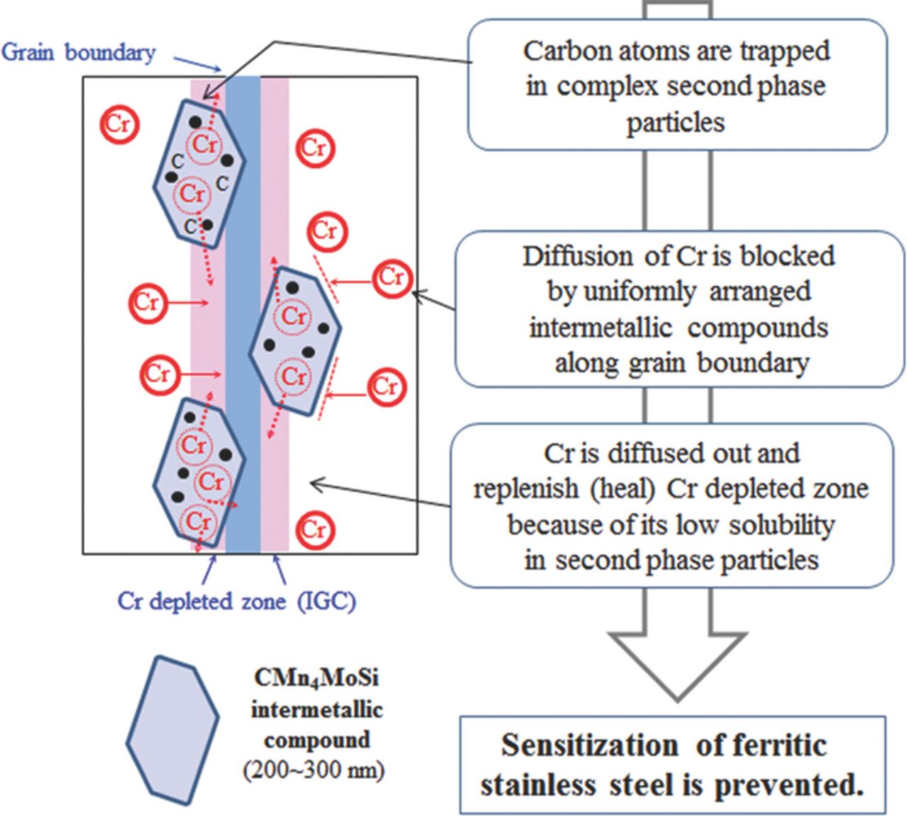
Figure 11. Schematics of IGC prevention mechanism operating in low-Cr ferritic stainless steel by co-addition of weak carbide formers.
This study proves that co-addition of weak carbide formers to low-Cr ferritic stainless steel can prevent IGC by formation of intermetallic compound along the grain boundary. In general, precipitation of an intermetallic compound may decrease toughness and mechanical strength depending on the size and distribution of the precipitate. The low-Cr ferritic stainless steel is not usually recommended for an engineering component requiring high toughness. Therefore, in this study, we did not specifically focus on the effect of precipitation of the intermetallic compound on the toughness and mechanical strength. For proper engineering applications, however, it is recommended to validate the mechanical property of the ferritic stainless steel when alloyed with co-addition of weak carbide formers.
Conclusions
A new alloy design concept with addition of the weak carbide formers works well to prevent IGC of low-Cr FSS. IGC occurring in low-Cr FSS can be prevented by the co-addition of proper amounts of Mo, Mn, and Si to form CMn4MoSi intermetallic compound along the grain boundaries. The TEM analysis proves that CMn4MoSi intermetallic compounds effectively suppresses segregation of Cr atoms along grain boundaries because the blocky intermtallic compounds occupy grain boudary areas. The segregation of C atoms along grain boundaries is suppressed by the formation of intermetallic compounds which trap C. Because of low Cr solubility in a CMn4MoSi intermetallic compound, Cr is diffused out of CMn4MoSi intermetallic compound and replinishes the Cr depleted area. By co-addition of proper amounts of weak carbide formers of Mo, Mn, and Si, segregation of Cr can be suppressed and IGC can be prevented in the low-Cr FSS.
Acknowledgments
This work was supported by POSCO research fund.