Abstract
In this work we characterize all-solid-state lithium-sulfur batteries based on nano-confined LiBH4 in mesoporous silica as solid electrolytes. The nano-confined LiBH4 has fast ionic lithium conductivity at room temperature, 0.1 mScm−1, negligible electronic conductivity and its cationic transport number (t+ = 0.96), close to unity, demonstrates a purely cationic conductor. The electrolyte has an excellent stability against lithium metal. The behavior of the batteries is studied by cyclic voltammetry and repeated charge/discharge cycles in galvanostatic conditions. The batteries show very good performance, delivering high capacities versus sulfur mass, typically 1220 mAhg−1 after 40 cycles at moderate temperature (55°C), 0.03 C rates and working voltage of 2 V.
Export citation and abstract BibTeX RIS

This is an open access article distributed under the terms of the Creative Commons Attribution 4.0 License (CC BY, http://creativecommons.org/licenses/by/4.0/), which permits unrestricted reuse of the work in any medium, provided the original work is properly cited.
During the past decade, the quest for promising next generation energy storage systems has led significant attention to secondary batteries with high specific energy such as lithium/sulfur (Li/S) batteries (1675 mAhg−1 sulfur at 2.15 V),1–6 which have 3 to 5 times higher energy densities than commercial state-of-art Li-ion batteries, e.g. LiNixMnyCozO2 (NMC) and LiNi1-y-zCoyAlzO2(NCA), 170 mAhg−1 of active cathode material at 4.5 V and 4.1 V, respectively.7 The inexpensive, abundant and environmentally benign nature of sulfur makes this battery more appealing for large scale application purposes (e.g. transportation, portable and residential applications) than other metal-ion battery systems. However, there are still numerous scientific and technical challenges for practical application. During discharge in Li/S batteries, lithium ions move spontaneously through the electrolyte from the negative electrode, typically lithium metal, silicon or tin-based compounds, to the positive sulfur electrode and S is ultimately reduced to form Li2S, while electrons flow through the external circuit. During charge, Li2S is oxidized back to S and Li+ by applying an external voltage. The overall electrochemical reaction is:
![Equation ([1])](https://content.cld.iop.org/journals/1945-7111/163/9/A2029/revision1/d0001.gif)
However, the electrochemical reduction of sulfur in Li/S battery occurs through the formation of a series of intermediate lithium polysulfides, Li2Sx (2 ≤ x ≤ 8).8,9 These intermediates are soluble in most liquid organic solvents/electrolytes and shuttling between the sulfur cathode and Li anode results in fast self-discharge during storage and low coulombic efficiencies during charging. Therefore, a grand challenge for Li/S batteries is to suppress this mechanism, for example by encapsulation or coating of the sulfur electrode,10–14 use of impermeable membranes,15 and/or the use of suitable electrolytes that minimize the solubility and diffusivity of the polysulfides.16–18 Another possibility is to use fast ion-conducting solids, i.e. solid electrolytes with an ionic conductivity (σ ∼ 10−4 to 10−1 Scm−1) comparable to that of standard liquid electrolytes (e.g. σ ∼10−2 Scm−1 for 1.0 M LiFP6 in organic solvent).19–22 However, only a few classes of solid state ionics, including some perovskite and Garnet type oxides23–26 and compounds of the NASICON27,28 and LISICON families29 have sufficient chemical and electrochemical compatibility toward lithium as well as high Li+ conductivity and low electronic conductivity.25,27,30–32 Recently, complex metal hydrides have been identified as promising candidates for energy storage and conversion.33 Lithium borohydride, member of the family of complex metal hydrides and well-known hydrogen storage material,34–36 has been studied quite extensively as a promising solid electrolyte material for lithium batteries in the past years.32,37,38 LiBH4 can exist as two different polymorphs, a room temperature orthorhombic phase (Pnma) with low ionic conductivity and a high temperature (T > 110°C, under atmospheric pressure) hexagonal phase (P63mc)35,39 with high ionic conductivity (∼1 mScm−1 at 120°C). High temperature (120°C) bulk-type all-solid-state lithium-sulfur and lithium-magnesium hydride batteries have been demonstrated by Unemoto et al.40 and Zeng et al.,41 respectively, using LiBH4 as electrolyte; thanks to its high conductivity above 110°C. There have been investigations to stabilize the high conductivity phase of LiBH4 at room temperature. Maekawa et al. reported that addition of lithium halides (LiI, LiBr and LiCl) stabilizes the hexagonal phase of LiBH4 at room temperature.42,43 Unemoto et al.44 used LiBH4-LiCl as electrolyte in solid-state Li/S batteries and Sveinbjörnsson et al.45 explored the performance of LiBH4-LiI solid solutions in lithium batteries.
Nanoconfinement of LiBH4 in nanoporous carbon scaffolds has been reported by various groups to improve the BH4− rotational diffusivity and lithium mobility at room temperature.46–49 However, due to their high electronic conductivity, nano-scaffolds of carbon are not very relevant for solid state ionics, whereas e.g. silica scaffolds are quite promising. Blanchard, de Jongh et al.30 investigated confinement effects on lithium ionic conductivity and mobility using ordered mesoporous silica. Nano-confining LiBH4 in ordered mesoporous SiO2 scaffolds (MCM-41) changes the stability of the different structural phases and leads to high Li+ conductivity (0.2 mScm−1) at 55°C. This makes the nanoconfined LiBH4 an attractive solid electrolyte for all solid-state batteries at ambient conditions. Nanoconfined LiBH4 is stable against temperature cycling, reported at least up to 140°C, and has a large electrochemical stability window of 6 V.30
In this work we demonstrate the prospective application of nanoconfined LiBH4 as a solid electrolyte in all-solid-state Li-S batteries operating at 55°C. We first validate the possibility to use the composite as solid-electrolyte (SE) by measuring the electronic (te), ionic (tion) and cationic transport numbers (t+); the most important characteristics for application of electrolytes in lithium (or other metal) batteries. Before application of the solid electrolyte in Li/S cell, its high electrochemical compatibility with the metal negative electrodes is tested and cyclic voltammetry (CV) of the cell is performed. Finally, we demonstrate that the Li/S batteries can deliver high capacities versus sulfur mass, typically 1220 mAhg−1 at working voltage of 2 V and 0.03 C rates for a large number of cycles.
Experimental
Preparation of the electrode materials
To improve the electrochemical activity of insulating elemental sulfur, composite electrodes made of sulfur and conductive components were prepared. We combined ballmilling, as suggested by Unemoto et al.40 and melt-diffusion, as suggested by Ji et al.,50 to optimize the dispersion of the sulfur on the carbon matrix. Conductive carbon additives were prepared by adding Ketjen Black EC-600JD (surface area 1400 m2g−1, pore volume 4.80-5.10 m3g−1, Shanghai Tengmin Industry Co., Ltd.) and activated carbon Maxsorb MCS-30 (surface area 3000 m2g−1, 1.7 cm3g−1, Maxsorb, Japan) in a weight ratio 1:1. The carbon blends were mixed with elemental sulfur (Sigma Aldrich, 99.9%) through ball milling (45:55, S:C weight ratio) for 30 min at 400 rpm, BPR (ball to powder ratio) ≈ 125:1 with a Fritsch Pulverisette P7. The obtained C/S mixture were afterwards heated at 155°C for 6 hours in sealed vessels under Ar atmosphere at a very slow rate (heating/cooling at 0.2°C/min) in order to diffuse the molten sulfur into the porous carbon. After cooling to room temperature, electrodes were made from the C/S composites by preparing slurries with N-methylpyrrolidinone along with 10–15% polyvinylidene fluoride (PVDF) stirred overnight. The slurries were casted onto the surface of Al current collectors and dried, between 50–60°C for 24 hours. After drying, electrodes were cut into disks with diameter of 10 mm. The final sulfur content in the C/S composites was determined by thermal gravimetric analysis (cf. supplementary information – Figure S1). X-ray diffraction patterns of pristine carbons (Maxsorb and KJ), elemental sulfur and composite carbon–sulfur powders are shown as supplementary information (Figure S2). The diffraction patterns were collected using a Rigaku Advance X-ray Diffractometer (2θ = 20–80°) working with Cu-Kα radiation (λ = 0.15418 nm). Scanning electron microscopy (SEM) images of the powder, pristine casted electrode and electrode after first discharge-charge cycle are shown in Figure S3 of the supplementary information.
Lithium foil (Sigma Aldrich, 99.9%, thickness 40 μm) was used as negative electrode for all the electrochemical measurements.
Preparation of the electrolyte
The solid-electrolyte ("SE"), i.e. nano-confined LiBH4, was prepared via infiltration of molten LiBH4 into mesoporous silica (MCM-41) as described in Ref. 51. MCM-41 scaffolds were synthesized according to the procedure described by Cheng et al.52 SiO2 (Aerosil 380), CTAB (cetyl(hexadecane)-ammonium bromide), TMAOH (tetramethylammonium hydroxide) and H2O were mixed in a ratio of 1:0.25:0.20:40 g. The mixture was stirred at 40°C for 1 hour and kept at this temperature for 20 hours, after which it was transferred to a Teflon-lined steel autoclave and hydrothermally treated at 150°C for 48 hours. The product was filtered, washed and dried at 60°C for 12 hours and at 120°C for 9 hours and then calcined at 550°C for 8 hours. Prior to melt infiltration, the synthesized MCM-41 (pore volume, 1.08 cm3/g, surface area = 947 m2/g and pore diameter of 4.4 nm) was dried at 300°C for 5 hours under a 25 ml/min Ar flow, and subsequently transferred into an argon filled glove box without exposure to air. The dried MCM-41 and LiBH4 (Aldrich, 98%) were mixed in a weight ratio of 1: 1.15 which corresponds to a 160% filling of the SiO2 total pore volume. The mixture was placed inside a graphite sample holder and inserted into a stainless steel autoclave. An initial pressure of 50 bar of H2 was applied and the mixture was heated at 3°C min−1 to 295°C and kept at this temperature for 25 min. at a final pressure of about 90 bar H2. Afterwards, the sample was cooled and transferred to an Ar-filled glove box.
Assembly of the cells and electrochemical measurements
The all-solid-state Li/S batteries were fabricated using in-house developed test cells in which the battery components were placed in a PolyEtherEtherKetone (PEEK) cylinder and pressed in between two stainless steel pistons serving as electrical contacts. In all cases, the SE was inserted in the cell as a powder and pressed against lithium metal, stainless-steel or C/S composite electrodes under 49 kPa. Typically 50 to 70 mg of sample was used, resulting in thicknesses of 0.5 to 1 mm (cell diameter ≈ 10 mm). With these masses of SE, the risk of a short circuit after pressing the cell is reduced and the SE layer is thin enough to avoid excessive resistance. Symmetric cells were assembled in two different configurations, e.g. blocking and non-blocking to cation (Li+), in order to determine the ionic (tion) and cationic transport numbers (t+) of the solid electrolyte, respectively. Hence, the electrolyte was sandwiched between two stainless steel electrodes (10 mm diameter) or Li electrodes for the blocking and non-blocking configuration, respectively. Galvanostatic platting-stripping cycles were examined using symmetric, non-blocking (i.e. lithium on both side) electrodes configuration. Cyclic voltammetry (CV) scans were performed in the voltage range of 1–3.5 V at a rate of 0.1 mVs−1. Galvanostatic discharges-charges have been performed in full Li/S cells at current densities up to 25 μA/cm2. The cutoff voltages for the cycle tests were set to 1 and 3.5 V for discharge and charge, respectively. All electrochemical tests have been performed using a Bio-Logic VMP3 potentiostat at 55°C (328 K). At 55°C the conductivity of the electrolyte is two times higher than at room temperature, 0.2 mScm−1 vs. 0.1 mScm−1, therefore this temperature was chosen to limit the ohmic drop in the solid-electrolyte and ensure complete redox reaction of the sulfur during the battery cycling.
Results and Discussion
Transport/transference number measurements
The transference number corresponding to the ionic (tion) transport has been determined for the nano-confined LiBH4 using the DC voltage polarization technique.53 A voltage of 0.5 V was applied across the SE, using stainless steel blocking electrodes on both sides, and the resulting current was monitored as a function of time (Figure 1). The mean value of the measured current during one hour is 5.10−4 μA/cm−2 and results from the instrumental noise. The ionic transport number (tion) was evaluated using the equation, tion = (iion)/iT, where iT, the initial current consists of the sum of the ionic (iion) and electronic (ie) currents giving iion = iT-ie, and ie is the final electronic current. The calculated value in this case is found to be tion ≅1, indicating that the current through the electrolyte is ionic, as there is no remaining current after the initial charging of the system.
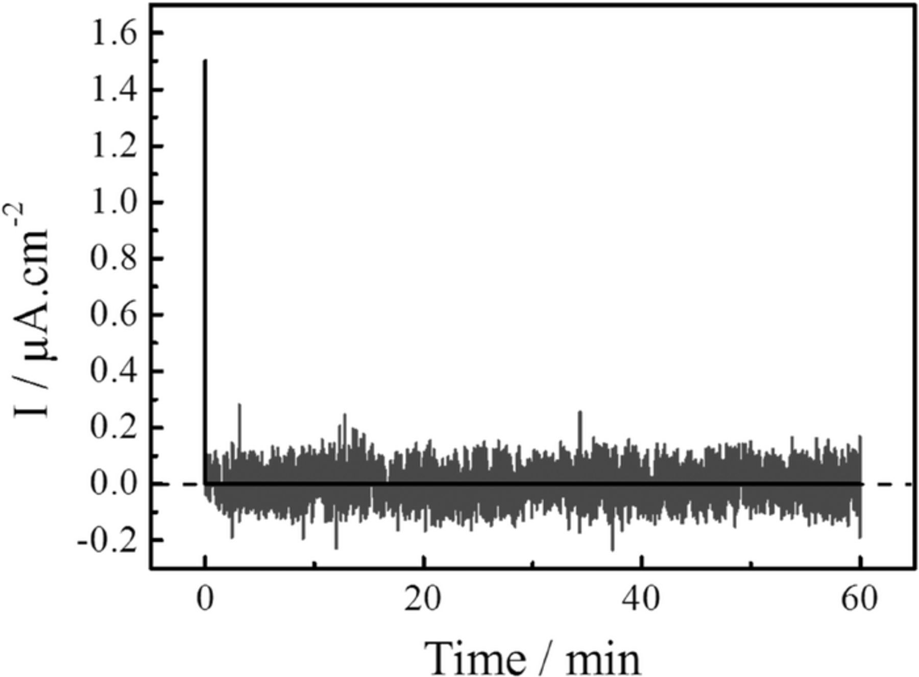
Figure 1. The current as a function of time for nano-confined LiBH4 in MCM-41 mesoporous silica solid electrolyte in between two blocking electrodes. The current decreases rapidly to zero, the plot shows the non-filtrated instrumental noise (gray line) and the mean value (black line).
The lithium transport number (t+) was estimated by following the procedure of Bruce, Evans and Vincent.54–56 The solid electrolyte is sandwiched between two cation reversible electrodes (in this case Li metal) and is polarized by the application of a small constant potential difference between the electrodes (ΔV = 10 mV). Under the electric field, positive and negative ions can migrate to the oppositely polarized electrode. For LiBH4, it should be the Li+ cations but also possibly the BH4− anions while for silica, the surface silanol groups (OH−)57 for example could also migrate. The anion concentration is depleted at the negatively polarized electrode and anions accumulate near the positively polarized electrode. Since the number of charge carriers (anions and cations) remains constant, electro-neutrality within the electrolyte must be maintained and a concentration gradient is established. As a consequence, the value of the initial current (I0) decreases with time until a steady-state current (Is), due to the sole migration of cations, is eventually observed (see Figure 2A). In ideal cases, a direct measure of Is and I0 is sufficient to calculate transport numbers (i.e. t+ = Is/I0), but in practical cells with active electrodes, the influence of the electrode processes have to be taken into account and, more specifically, the possible changes of resistivity at the electrolyte-electrode interface with polarization. Therefore, Electrochemical Impedance Spectroscopy (EIS) measurements were performed to evaluate the resistivity of the cell prior to (R0) and after (Rs) the polarization procedure, in order to correct for changes in the electrode-electrolyte interface (Figure 2B). For the nano-confined LiBH4 in MCM-41, the transport number of lithium cation (t+) has been evaluated to be 0.96 using Equation 2 and the measured values of Is, I0 and Rs, R0 (Figure 2).
![Equation ([2])](https://content.cld.iop.org/journals/1945-7111/163/9/A2029/revision1/d0002.gif)
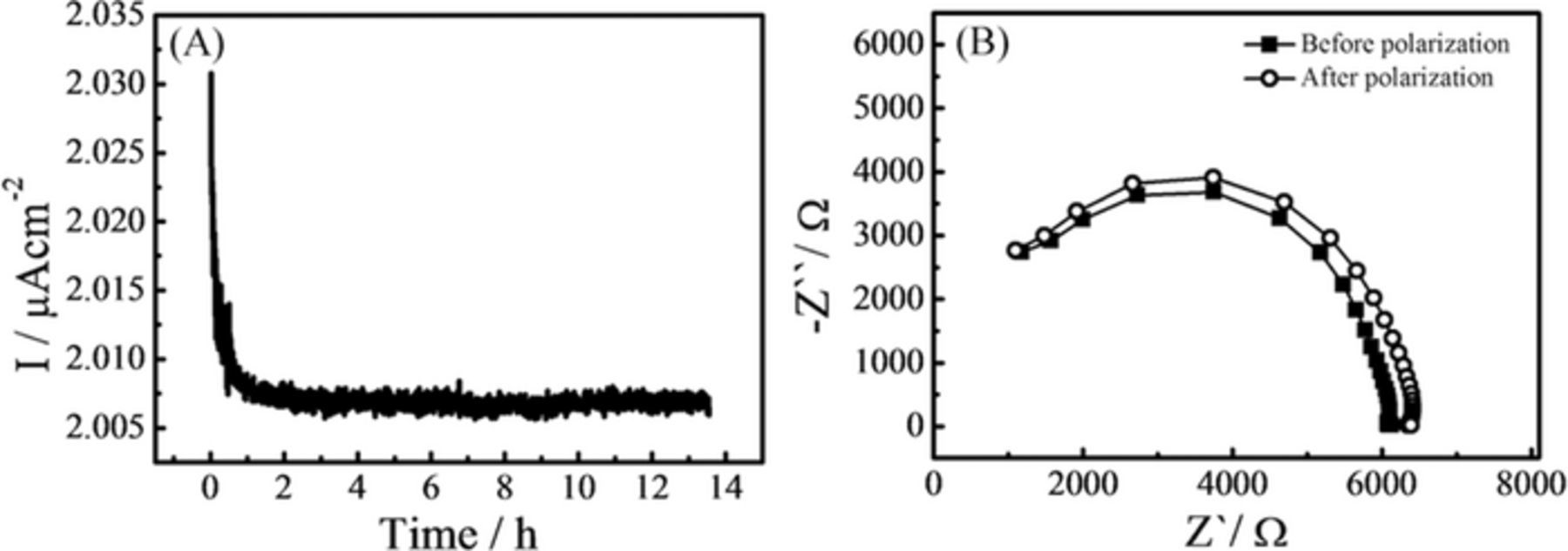
Figure 2. (A) Variation of current with time during polarization and (B) Electrochemical Impedance Spectroscopy of the cell before and after polarization of nano-confined LiBH4 in MCM-41 mesoporous silica.
Transport numbers of other nano-confined LiBH4 electrolytes (with different types of mesoporous scaffolds, different geometry and size of the pores and amount of LiBH4 confined in the pores) determined by the same methods are tabulated in the supporting information (table S1). The obtained values for t+, ranging from 0.9 to 0.96, prove that the charge transport in these systems is due to the migration of Li+.
Symmetrical cell cycling performance
The stability of the electrolyte in contact with lithium metal was investigated by galvanostatic plating-stripping cycles using symmetric Li electrode cells. The measurements were performed by applying a constant current density of 300 μA/cm2, resulting in voltage of about 0.2 V and inversing its polarity every 15 minutes. The regular voltage-time profile is shown in (Figure 3). A small increase in the voltage (10 mV) is recorded in the course of the measurement, corresponding to an increase of the cell resistivity by 4.5% starting from an initial value of 227 Ω. It is possibly due to partial loss of electrical contact at the electrode/electrolyte interface, because of the solid nature of the electrolyte. Nevertheless, the increase in the cell resistivity is small and this measurement shows the good stability of the electrolyte in contact with lithium metal over many cycles.
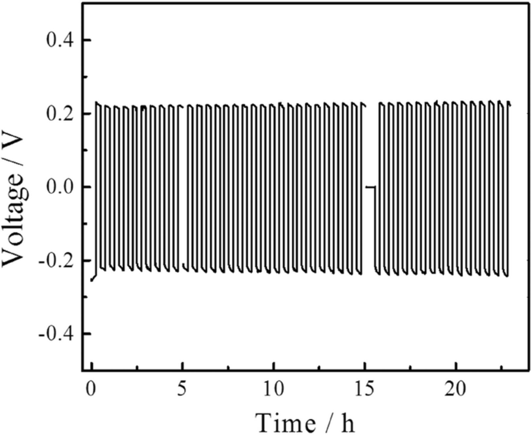
Figure 3. Voltage profile of LiBH4 nano-confined in MCM-41 mesoporous silica pressed in between two Li electrodes in a symmetrical cell. 45 cycles of plating-stripping were performed.
Cyclic voltammetry
Cyclic voltammograms have been recorded on the all-solid-sate Li/S batteries in the voltage range of 1–3.5 V at scan rates of 0.1 mVs−1. In general, the reduction of sulfur in Li/S batteries occurs in a two or three steps depending on the specific choice of electrolyte, e.g. the first step is the reduction of sulfur to lithium polysulfides (Li2Sn, 2 < n < 8) in the range of 2.4–2.1 V vs Li/Li+ and the second represents further reduction of polysulfides to solid lithium sulfides (Li2S2 and Li2S) at around 2.1–1.8 V.8,9 During the second cycle of the voltammetry, and onwards, a reduction peak around 1.4 V and an oxidation peak at 2.4 V were observed during cathodic and anodic scans, respectively (Figure 4). The reduction peak at 1.4 V can be attributed to the formation of polysulfides, whereas the anodic peak, at 2.4 V is ascribed to conversion of lithium sulfides to elemental sulfur and lithium. The reduction and oxidation peaks do not vary significantly during cycling, but the cathodic peak area is larger than that of the anodic peak. The differences in the areas might arise from a too high sweeping rate used for the measurement, i.e. that the rate of electron transfer is insufficient compared to the rate of mass transfer, transfer of Li+ to S and LixSy.58 This could be due to an insufficiently high electronic conductivity of the C/S composite electrode. During the first cycle a small shoulder on the cathodic peak appeared around 2.2 V. This suggests an electrochemical reaction of LiBH4 with the sulfur electrode. However, as it is only present during the first cycle, it seems that a stable cathode-electrolyte interface (CEI) is formed, and there is little effect on the battery charge-discharge cycling and capacity. During the first scan the cathodic charge was much larger than during subsequent scans, and likewise a parasitic current was observed during the first discharge of the full battery, making the first discharge capacity much larger than expected (see below).
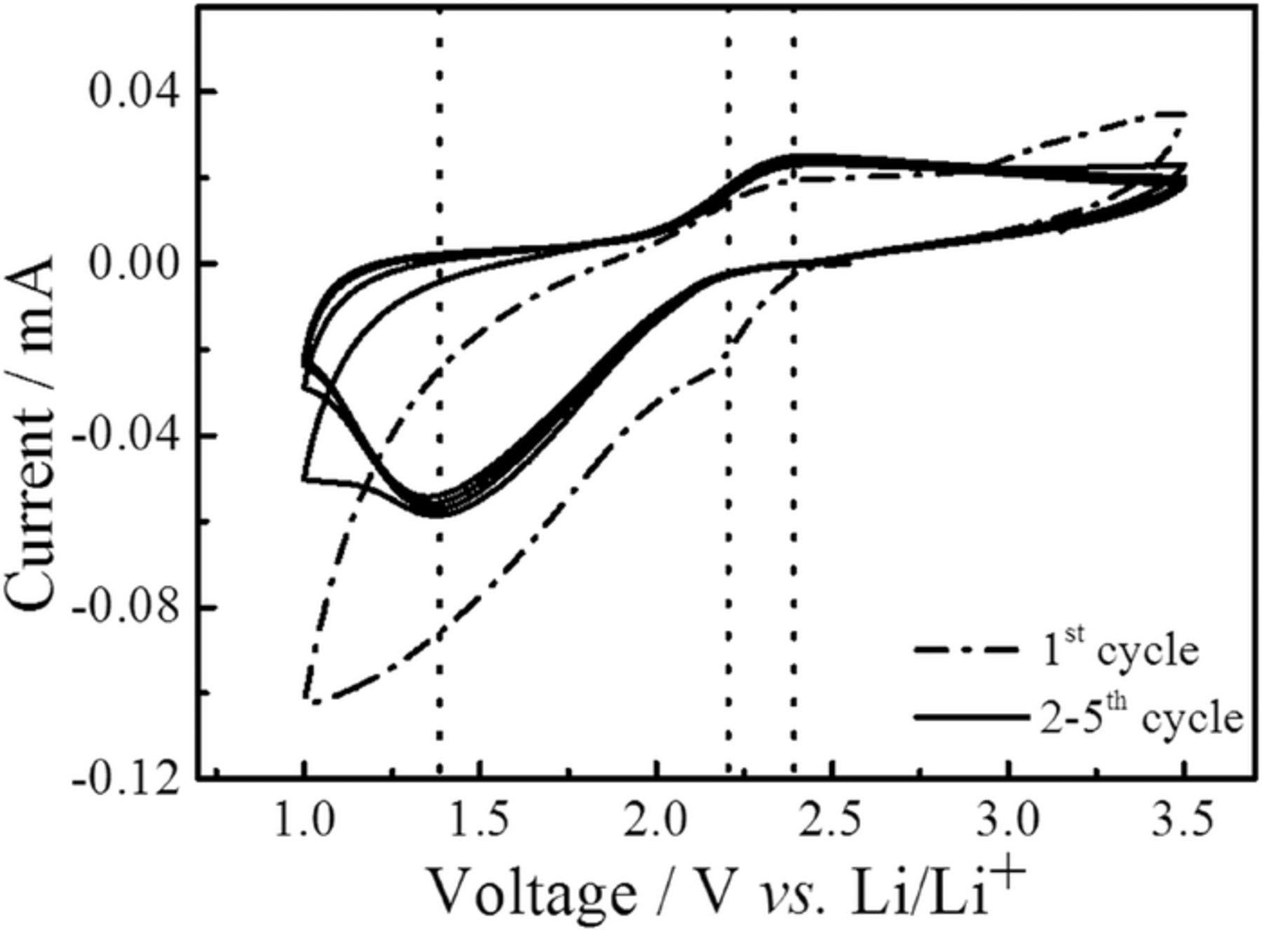
Figure 4. Cyclic Voltammogram of an all-solid-state Li/S battery at a scan rate of 0.1 mV/s and temperature of 55°C.
Charge-discharge cycling of all-solid-sate Li/S batteries
Figure 5A gives a typical example of the charge-discharge voltage versus capacity curves measured during the cycling of an all-solid-state Li/S battery at 55°C. Cycling was performed at current density of 6.2 μA/cm2, corresponding to C-rates of 0.03 C, and with cutoff voltages of 1 and 3.5 V. The high coulombic efficiencies of 99.6 ± 0.2% from cycle three onwards, shown in Figure 5B demonstrates the good cycling stability of the battery. During the second discharge, we recorded a capacity of around 1570 mAhg−1 of sulfur, which corresponds to 94% of the theoretical discharge capacity (1675 mAhg−1). The capacity gradually decreases to 78% of this value for cycle 40. The increase of the overall resistivity of the cell during cycling could be the reason for the apparent loss of the capacity (see the impedance spectra in Figure S4). The increase in the resistivity might arise from the formation of an insulating interface between the SE and the electrodes or a loss of contact between the two. During discharge, the lithium stripping and formation of lithium polysulfides does not seem to provoke any dramatic increase of the interfacial resistivity as the discharge curves show a reasonably flat and stable plateau around 2 V.
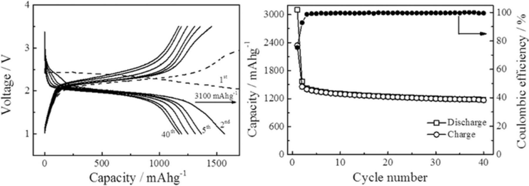
Figure 5. (A) Cycling performance, (B) Discharge/Charge capacity and Coulombic efficiency of a solid state Li/S batteries at a rate of 0.03C and at 55°C.
During the first discharge, the cell exhibits a much larger capacity than the theoretical capacity calculated form the expected electrochemical reaction depicted in Eq. 1. The discharge curve shows the presence of two distinct plateaus (Figure S5): one at high voltage, around 2.4 V and one at lower voltage, 2 V. While the second one can be attributed to the reduction of S to Li2S (Eq. 1), the first one seems to be due to parasitic processes as also observed during the cyclic voltammetry (Figure 4) and most likely due to electrochemical reaction of LiBH4 with the positive electrode material forming a cathode-electrolyte interface (CEI). This unexpected high capacity has already been observed for other type of all-solid-state batteries based on lithium borohydride solid-electrolytes,3,45,59 and was attributed to possible reaction of lithium with the carbon matrix.59 The product(s) of this parasitic reaction(s) seems to be partially reversibly cycled. Indeed, the first charge curve shows a second plateau above 3 V (Figure S5), suggesting the existence of at least two different electrochemical reactions. However, full oxidation of the product(s) form during the parasitic reaction(s) is not achieved before the cutoff voltage is reached and the plateau fades in the following cycles. The exact nature of this parasitic reaction is a topic of ongoing research.
The full cell resistivity increases from an initial 1.2 kΩ to 1.8 kΩ after the first cycle and about 5 kΩ after the 40th cycle. Clearly, the increase of resistivity is larger during the first discharge cycle (∼50% increase) than during the following cycles (∼2.5%). Further experiments are required to provide a detailed understanding of the origin of the additional capacity during the first battery discharge, but the CEI formation, during the first discharge, does not seems to be detrimental for the further cycling of the battery.
The rate capability of a full Li/S cell was investigated by cycling at charge-discharge rates varying from 0.03 C to 0.12 C with cutoff voltages of 1 and 3.5 V. The discharge capacities obtained at different rates are presented in Figure 6. Although the capacities are lower at higher C-rates, full capacity is regained when lowering the rates again and for example during the 34th cycle, the measured capacity is similar to the one obtained during the cycling of the battery presented in Figure 5. However these results stress that the sulfur electrode polarization is an important issue to address. At high C-rate the potential drop in the C/S electrode is large and impedes full sulfur utilization. The recovering of the full capacity after lowering the discharge rate highlights the good stability of the all-solid-state Li/S battery using a nano-confined LiBH4 electrolyte.
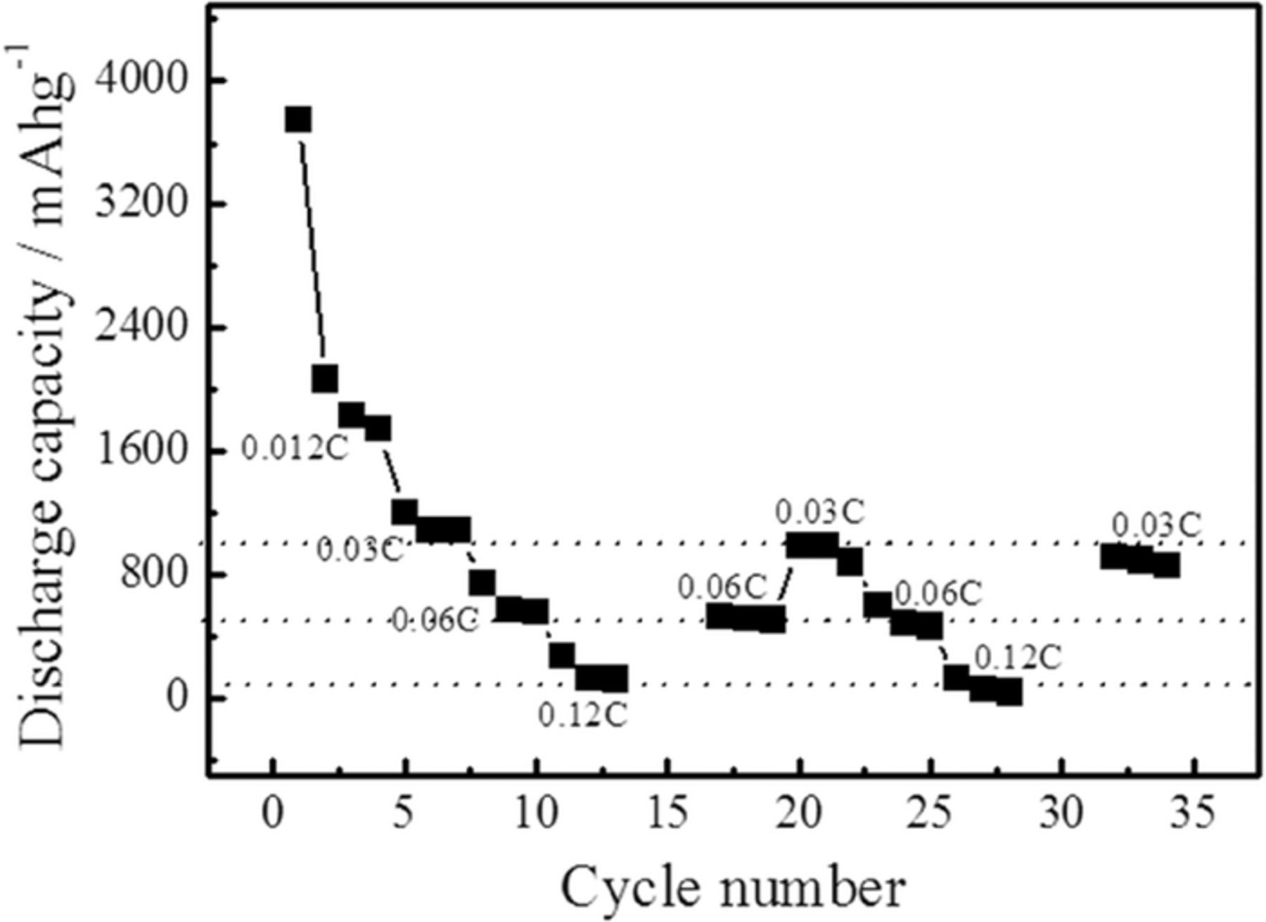
Figure 6. Rate capability of all-solid-state Li/S battery at different C-rates.
Figure 7 shows X-ray diffraction patterns of the positive electrode materials collected from disassembled cells, one after the first discharge and one after the first charge. Because the cells are made of a powdered SE pressed against the casted composite S/C electrode it is difficult to fully separate the two components afterwards and for that reason, the LiBH4 reflections are also found in the diffraction patterns and it is impossible to observe the CEI product(s). For the discharged cathode, we identify peaks from Li2S (Figure 7 right), whereas no traces of polysulfides or crystalline S were observed. In the case of the C/S material, extracted from the recharged battery, sulfur reflections are clearly visible. This is in agreement with the appearance of features with typical size of few hundreds of nanometers as observed in the SEM (Figure S3).
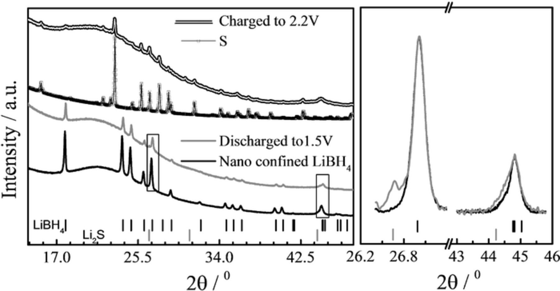
Figure 7. XRD patterns of composite cathode after 1st discharge (red) and charge (orange). For comparison, the patterns for nano-confined LiBH4 (green) and sulfur (red) are also shown. The red ticks show the position of Li2S Bragg peaks and the green of LiBH4. The graph on the right is a magnification of the two rectangular zones of the left graph. The diffraction patterns have been shifted vertically for easier comparison. It shows the evidence of Li2S reflections after discharge. The large variation in the background, around 20–25 degrees are due to the MCM-41 and/or the Ketjen Black and activated Maxsorb carbon.
The diffraction patterns clearly confirm that during the charge-discharge cycling, the reduction of S to Li2S, according to Eq. 1, is the electrochemical reaction. From the discharge plateau (Figure 5), and at least from cycle 10 and onwards, it seems that only one reaction occurs. However, it is reasonable to state that polysulfides are formed as intermediate products.
Table I compares our present results to published results on all-solid-state lithium/sulfur batteries. Only few of the tested cells retained capacities above 1000 mAh.g−1. The best results reported in literature were obtained at lower rates and/or fewer cycles and at low temperature (25°C). A high capacity (1200 mAh.g−1 S after 10 cycles) was obtained at 0.2C by Nagata et al.60 and Zhang et al.61 reported a capacity of 634 mAh.g−1 S after 100 cycles at 0.1C. We achieved with the nano-confined LiBH4 based Li/S batteries high capacities for a consequent numbers of cycles, albeit at intermediate C-rates and temperatures, thin electrodes and low sulfur loadings.
Table I. Latest published data for all-solid-state Li/S batteries.
| MCM-41 LiBH4 | 1220 | 0.12 | 55 | 0.03 | 40 | |
| Li2S-P2S5 | 400 | 0.88 | 80 | 0.05 | 17 | 63 |
| LiBH4-LiCl | 600 | 1.33 | 100 | 0.03 | 5 | 44 |
| PEO-nanoclay-LiTFSI | 634 | 1.2 | 60 | 0.1 | 100 | 61 |
| LiBH4 | 700 | - | 120 | 0.05 | 45 | 64 |
| Li10GeP2S12 | 800 | 4.80 | 25 | 0.03 | 10 | 65 |
| 600 | 25 | 0.075 | 10 | |||
| Li2S-P2S5 | 860 | 2.22 | 25 | 0.03 | 20 | 66 |
| Li6Ps5Br | 1080 | 2.26 | - | 0.1 | 50 | 67 |
| a-Li3PS4 | 1200 | 4.3 | 25 | 0.014 | 50 | 68 |
| Li10GeP2S12 | 1200 | 4.8 | 25 | 0.2 | 10 | 60 |
| Li3.25Ge0.25P0.75S4 | 1300 | 1 | 25 | 0.06 | 20 | 59 |
Nano-confined LiBH4 exhibits better properties than the solid-electrolytes used in sulfur batteries reported so far. It has a wider electrochemical stability window, 6 V versus 5 V reported for thio-LISICON (e.g. Li3.25Ge0.25P0.75S4 ).62 It is stable against Li metal, while Li-In or Li-Al negative electrodes have to be used with thio-LISICON62 thus reducing the gravimetric energy densities of the cells by introducing extra weight. Gravimetric energy densities of 100 Wh.kg−1 have been obtained for the cells tested in our present study (the calculation takes into account the full battery weight and measured capacities after at least 10 cycles). To increase this value, several optimizations can be considered. Firstly, an evident step is to use thicker positive electrodes to increase the amount of sulfur with the possibility to incorporate a fraction of solid-electrolyte as performed in most of the studies (see refs. in Table I). Secondly, optimization of the electronic transport and sulfur distribution in the C/S composite has not been performed yet. It has been proved to be of great influence.59 Finally, reducing the thickness of the solid-electrolyte layer will decrease the volume and mass of the battery.
Conclusions
We have demonstrated that nano-confined LiBH4 in mesoporous silica (MCM-41) scaffolds has excellent properties for a solid-electrolyte. It exhibits a high Li+ conductivity of 0.2 mScm−1 and 0.1 mScm−1 at 55°C and room temperature, respectively. Its cationic (t+) and electronic (te) transport numbers, of values close to 1 and 0 respectively, are ideal for a solid electrolyte. It has an electrochemical stability window of at least 6 V. The electrolyte is stable in contact with lithium metal, there is no need to use lithium alloys instead and batteries of high gravimetric energy densities can be assembled.
The all-solid-state Li/S batteries using this nanoconfined LiBH4 show high efficiencies in the utilization of the sulfur with good stability of the voltage during the discharge. 10% decreases of the voltage, on average from 2.1 to 1.9 V, are observed. This is a significant advantage when compared to Li/S batteries based on liquid electrolyte for which multiple voltage plateaus are present during the discharge because of the formation of the different polysulfides.
Our all-solid-state Li/S batteries deliver capacities, as high as 1220 mAh.g−1 S retained over at least 40 cycles at 55°C. This is, to date, the first report of Li/S batteries based on LiBH4, achieving such high capacities at moderate temperature.
Acknowledgments
The authors acknowledge support from the Danish Agency for Science, Technology and Innovation (DASTI) through the project InterBat (Interfaces and Reactions in Batteries) and from the COST action MP1103. Petra de Jongh acknowledges financial support from the Netherlands Organisation for Scientific Research (NWO-ECHO).