Abstract
There is great interest in elucidating the corrosion mechanism of magnesium, and different experimental methods and techniques are explored with this purpose. Among the scanning probe techniques, scanning electrochemical microscopy (SECM) is delivering some promising results in recent years. In particular, the use of ion selective microelectrodes (ISME) as SECM sensing probes allow monitoring of the temporal and spatial distribution of different ionic species related to the corrosion reactions. However, a serious disturbance in the measured potential can be observed when it comes to galvanic coupling or polarization of the samples. This work explores the factors that affect the magnitude of the electrical field effects associated with the galvanic coupling, and describes an experimental arrangement for potentiometric SECM able to avoid the unwanted contribution of the potential field. The performance of a double barrel electrode assembly comprising an ion selective microelectrode and an internal reference electrode was compared to that of a conventional single barrel ISME in order to establish its applicability for the investigation of corrosion systems presenting electrical field distributions.
Export citation and abstract BibTeX RIS

This is an open access article distributed under the terms of the Creative Commons Attribution Non-Commercial No Derivatives 4.0 License (CC BY-NC-ND, http://creativecommons.org/licenses/by-nc-nd/4.0/), which permits non-commercial reuse, distribution, and reproduction in any medium, provided the original work is not changed in any way and is properly cited. For permission for commercial reuse, please email: oa@electrochem.org.
The investigation of magnesium corrosion attracts great interest to corrosion scientists in order to elucidate its corrosion mechanism as well as to design methods of protection or even develop a stainless magnesium material. It is also an important issue in relation to the industrial needs of advanced functional materials, taking into account the advantageous characteristics of magnesium. Although there are many reports on magnesium corrosion, when dealing with anodic polarization, the actual mechanism remains a matter of debate.1–6 Scanning electrochemical microscopy (SECM) has been introduced in the investigation of the corrosion of magnesium due to its combination of spatial and chemical resolution,7,8 including in situ monitoring of released Mg2+ ions using ion-selective microelectrodes.9,10 We recently proposed a combined amperometric/potentiometric strategy to investigate the corrosion behavior of a twin Mg sample, where anodic and cathodic sites could be spatially separated and studied individually.11 The experiments were performed using separate probes for amperometric and potentiometric operations, thus requiring the exchange of tips or even conducting separate experiments in each case. It would have been advantageous to use combined probes for simultaneous detection so that time resolution could be enhanced a further step. In fact, it was shown that it is possible to apply double-barrel electrodes for either combined potentiometric Zn2+ and pH measurements,12 or combined amperometric and potentiometric detection of corrosion products.13 Although multi-species potentiometric detection could be performed simultaneously while the probe scanned the sample under investigation, the combined amperometric/potentiometric operation was exclusively quasi-simultaneous. The reason was that operation of the amperometric tip affected the signal measured by the potentiometric tip in the case of simultaneous measurements. Unfortunately, the effects of the electrical field on the potentiometric measurement of SECM are also induced by corroding galvanic pairs.14 Therefore, for simultaneous SECM monitoring of the Mg2+, pH and H2 distributions in corroding magnesium systems, the local effects of the electrical field must be suppressed or greatly reduced. If this disturbance were eliminated, a new experimental route would be opened to the corrosion scientists to obtain new insights on the corrosion of magnesium.
Multi-barrel electrodes are applied in neuroscience.15–17 Potentiometric multi-barrel probes are normally prepared with the reference included in the multi-barrel body,18,19 an arrangement used in 1996 by Park et al. to monitor local pH distributions on Al3Fe galvanically coupled to Al 6061 in 0.6 M NaCl,20 the only occurrence of such kind of probe in either corrosion science and potentiometric SECM until now. Indeed, this assembly has been used when the measurement takes place in excitable tissues, because the effect caused by the locally generated electrical potentials were thus minimized.21 Although this is not true in all cases, for instance, nerve spike potentials cannot simply be canceled,22 it seemed worth to examine in more detail the applicability of these assemblies in corrosion science.
In this contribution we continue studying the effect of different physicochemical characteristics of the galvanic corrosion on the potentiometric signal of Mg2+ selective microelectrodes, and we propose a novel probe assembly capable of eliminating any other contribution to the measured potential apart from the actual Nernstian response.
Experimental
Electrode preparation
Mg ion selective microelectrodes (ISME) containing a solid contact configuration were employed in this work due to their superior characteristics compared to conventional liquid contact arrangements as described previously.9 In brief, micropipettes were pulled from borosilicate capillaries (Hilgenberg GmbH, Germany) with a P-30 type capillary puller (Sutter Instruments Co., CA, USA). The inner surface of the capillaries was hydrophobized by 1 h exposition to saturated dichlorodimethylsilane (Sigma-Aldrich, Taufkirchen, Germany) at 120°C. The ion selective cocktail contained 1.5% bis-N,N,dicyclohexyl-malonamide ionophore,23 2.6% high molecular weight poly(vinyl chloride) (PVC), 1.4% potassium tetrakis(4-chlorophenyl)borate, and 94.5% ortho-nitrophenyl octyl ether. The ionophore cocktail was front filled into the micropipette by applying vacuum from the other end of the capillary to produce the single barrel ISME, whereas back filling of the cocktail was employed in the case of the double barrel ISME/reference assembly. A 33 μm diameter carbon fiber (Specialty Materials Inc, Lowell, MA, USA) served as the solid contact of the ISME, prior electrochemically-coated with (poly-3,4-ethylenedioxythiophene) (PEDOT) conductive polymer doped in 0.1 M KCl.
Double barrel capillary probes were prepared by joining together two single barrel capillaries. The joining procedure involved the two capillaries being heated and twisted by 90° using a Narishige PE-2 puller (Tokyo, Japan). The resulting twisted double barrel capillaries were pulled in another heating process to obtain the desired final micrometer size double pipette tip. In order for the reference electrode and the ISME to be together in the same probe, selective silanization of one barrel had to be implemented using the following simple procedure. An orifice (1.0 mm dia.) was drilled through the plastic screw cap of a glass vial, and a capillary of 1.0 mm outer diameter was inserted and tight fixed in the hole to protrude by 1–2 cm in the upper part. This protruding capillary was inserted into the lumen of the barrel intended to be silanized. The barrel to be used for reference electrode making was filled up with ultrapure water (Millipore water system, specific conductivity κ = 5.6 × 10⁻⁶ S cm−1; Merck Millipore, Billerica, MS, USA) in order to avoid silanizing fumes entering the tip. 200 μl silanization solution was introduced in the vial (total volume of about 4 ml) and then the vial was closed it with the screw cap. In this way the double barrel body was held vertically with the pointy tip facing up so that the dimethyldichlorosilane vapor could easily enter the ISME barrel while the other barrel was not connected to the vial chamber. The system was placed in an oven for 1 h at 50°C. Finally, the ISME barrel was backfilled with the cocktail and the solid contact was introduced by positioning the PEDOT coated, doped carbon fiber solid contact as close as possible to the end of the capillary, typically 1–2 mm depending on the opening width of the barrel. The other barrel was filled with 0.1 M KCl, and a chlorinated silver wire was introduced therein. The sketch and micrographs of the double barrel probe are given in Figures 1A–1C. The individual barrels had orifice diameters in the range of 15–25 μm, and the spacing between the ISME and the reference electrode was estimated at 10–20 μm. The Mg ion selective microelectrodes were calibrated using standard solutions of MgCl2, and the calibration curve obtained (E vs. −log[Mg2+]) is shown in Figure 1D. The response time of the electrodes was determined using a homemade assembly24 that provided a very quick activity step. The response time was usually found between 0.2–0.3 s depending on the size of the tip orifice of the ISME. Sketches describing the fabrication sequence of the double barreled ISME and a conventional single-barrel configuration are given Figure 2A and Figure 2C for easy comparison.
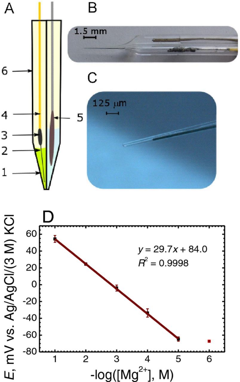
Figure 1. New double barrel electrode assembly for potentiometric SECM: (A) Sketch, and photographs of the (B) double barreled electrode and (C) its tip. 1: Mg2+ ion selective cocktail, 2: PEDOT coated carbon fiber (∅ = 33 μm), 3: silver epoxy glue; 4: copper wire for electrical connection; 5: Ag/AgCl micro-reference electrode; 6: double barrel borosilicate capillary. (D) Calibration plot of the potentiometric response of the Mg2+ ion selective microelectrode in MgCl2 solutions.
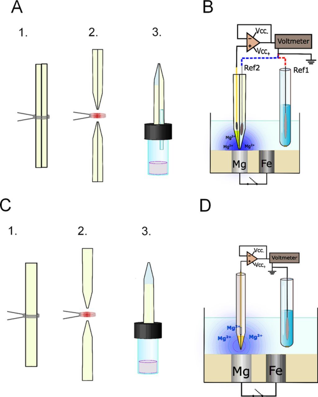
Figure 2. Sketches describing (A,C) the experimental procedure employed for the fabrication of the ion-selective microelectrodes used in this work, and (B,D) the measuring configuration for potentiometric SECM operation. ISME design: (A,B) double-barrel microelectrode arrangement containing an in-built internal reference electrode; (C,D) single microelectrode tip and external reference electrode placed in the bulk of the electrolyte. Fabrication steps: (1,2) capillary pulling, (3) selective silanization.
Sample preparation
Magnesium coupled to other less active metals were used as model corrosion systems. The first combination was prepared from 99.99% purity iron foils (Goodfellow, Cambridge, UK) and AZ63 alloy sacrificial boiler anode. Square base rods with cross section of 1 mm2 were cut from the foil and the anode, and placed vertically within a home-made assembly. A metal rod of each material was wrapped vertically in epoxy resin (EpofixKit, Struers, Denmark) with their transverse square surface facing up. Mg/AZ63 samples were prepared with various spacings between the metals, namely 1.5, 4.4, 7.2, 10, and 12 mm. Copper wires were soldered to portions of the specimens protruding from the resin sleeve to provide electrical connection from the rear side of the mold, while the other ends of the metal rods surrounded by the resin were exposed to the test electrolyte.
A second set of galvanic pairs was prepared in order to investigate the effect of the nature of the galvanic pair. Although the samples were prepared similarly to those described above, in this case, metal wires (∅ = 0.125 mm) of the pure metals were employed, namely copper, aluminum, iron, zinc and magnesium (Goodfellow, Cambridge, UK). The separation between Mg and any other metal was 6 mm in all cases.
Scanning electrochemical microscopy
SECM experiments were performed using an instrument manufactured by Sensolytics (Bochum, Germany) and operated with an Autolab bipotentiostat (Metrohm Autolab BV, Utrecht, The Netherlands) equipped with a high quality stepper motor-controlled XYZ-positioning system with 25 mm range and 20 nm resolution in each axis; all the components were controlled with a personal computer. A homemade voltage follower based on a 1012 Ω input impedance operational amplifier (mod. TL071, Texas Instruments, Dallas, TX, USA) was interconnected between the cell and the potentiometric input of the system.24 The electrochemical cell was completed with an Ag/AgCl/(3 M) KCl electrode as reference (E0 = +0.197 V vs. NHE). All potential values refer to the Ag/AgCl/(3 M) KCl electrode, except when the chlorinated silver wire microelectrode constructed in the double barrel probe was employed. Figures 2B and 2D depict the different measurement arrangements and connections required to perform the potentiometric SECM operation depending on the use of an internally in-built microreference electrode (Ref. 2) or an external conventional reference electrode (Ref. 1) in the bulk of the electrolyte. The establishment of an accurate tip-sample measuring distance is less straightforward when ion selective microelectrodes are employed as tips. In amperometric operation, the active microdisk electrode tip can be polarized as to produce a feedback response as the tip approaches the sample. Since ISME's cannot be polarized, approach curves cannot be recorded in this case. On the other hand, the ISME response is significantly less sensitive to the tip-sample distance within for distances up to one tip diameter. Hence, here the gentle approach method was used, meaning that the step by step approach of the tip toward the surface while the tip-sample distance was continuously monitored with the aid of an optical microscope. As the tip gently touched the sample, the tip could be lifted to the desired tip sample distance using the Z-micropositioning device under computer control.
Results and Discussion
An SECM employing potentiometric ion selective microelectrodes provides spatially resolved concentration distributions of a certain ion of interest with high selectivity. In this work, micropipette type Mg2+-selective electrodes were scanned above the Mg samples acting as anodes in various galvanic pair arrangements. As mentioned before, the measured potentiometric open circuit cell voltage between the ISME and the reference will not only contain the desired chemical information on the ion under investigation, but also some field potential contribution from the electrical field developed in the electrolyte by the galvanic pair system. The occurrence of such a signal coupling may contribute greatly to uncertainties in the measurement. It was observed that the extent of this unwanted contribution of the electrical field would be greatly affected by the physicochemical characteristics of the galvanic system, and the geometry of the experimental set up. The complex contributions of these two components on the measured voltage calls for special care and caution when local ion activity values are estimated directly from measured voltage values. In order to circumvent the uncertainty, the factors influencing the system response were identified and considered separately.
Tip-sample distance
Indeed, the distance between the ISME and the sample can affect the contribution of the electrical field to the measured signal. A first series of experiments was conducted controlling the distance between the tip and the sample using the micropositioning system incorporated in the SECM instrument. Other conditions, such as the concentration of the test electrolyte (0.001 M NaCl solution), and the horizontal distance between the ISME and the reference electrode were kept fixed. The AZ63-Fe pair consisted of rectangular metal surfaces of approximately 1 mm2, with a separation of 1.5 mm between the two metals embedded in epoxy resin. Freshly finished surface samples were employed for each measurement. Initially, the ISME was placed approximately over the center of the Mg alloy sample at a chosen vertical distance between them, and remained there for the rest of the experiment. Data acquisition was initiated after the ISME reached a stable potential value (typically a few seconds), and was performed at a frequency of 100 Hz. The copper wires soldered to the rear of the metals were connected to a bread board, in order to facilitate an easy procedure to electrically connecting/disconnecting the galvanic coupling between AZ63 and Fe. Fig. 2B shows the scheme of the experiment.
Figure 3 shows a representative collection of constant tip height recordings measured above the AZ63 and Fe samples for various tip-sample distances. As soon as the galvanic coupling was established, a sharp jump was observed in the potential signal recorded at the ISME. The noisy trace of the plots was due to the vigorous evolution of H2 bubbles that began at the moment of establishing the galvanic coupling between the metals. Such vigorous gas evolution upon galvanic coupling is notoriously different from the small bubbles that could be observed on the surface of the spontaneously corroding Mg alloy in larger time scale experiments. The potential jump was sensed even for the large tip-sample distance of 1000 μm, a distance too large for this potential change to arise from the diffusion of Mg2+ after only 30–60 s exposure of the sample to the test electrolyte. This implies that the recorded signal almost exclusively arose from the effect of the electrical field, because the measured potential returns to values close to the original ones after disconnecting the galvanic pair. The smaller the tip-sample distance was, the greater the potential jump. Thus, the line scan recorded using a tip-sample distance of 10 μm showed a potential jump of 40 mV, a value that would correspond approximately to almost two orders of magnitude misreading of the Mg2+ activity from the calibration plot in Figure 2. Unfortunately, the tip-sample distance in a typical SECM measurement is less than 100 μm, and sensitivity cannot be compromised using larger tip-sample distances, because although the potential jump is certainly less, we could lose spatial resolution of the chemical information above the corroding sample when the distance is too large.
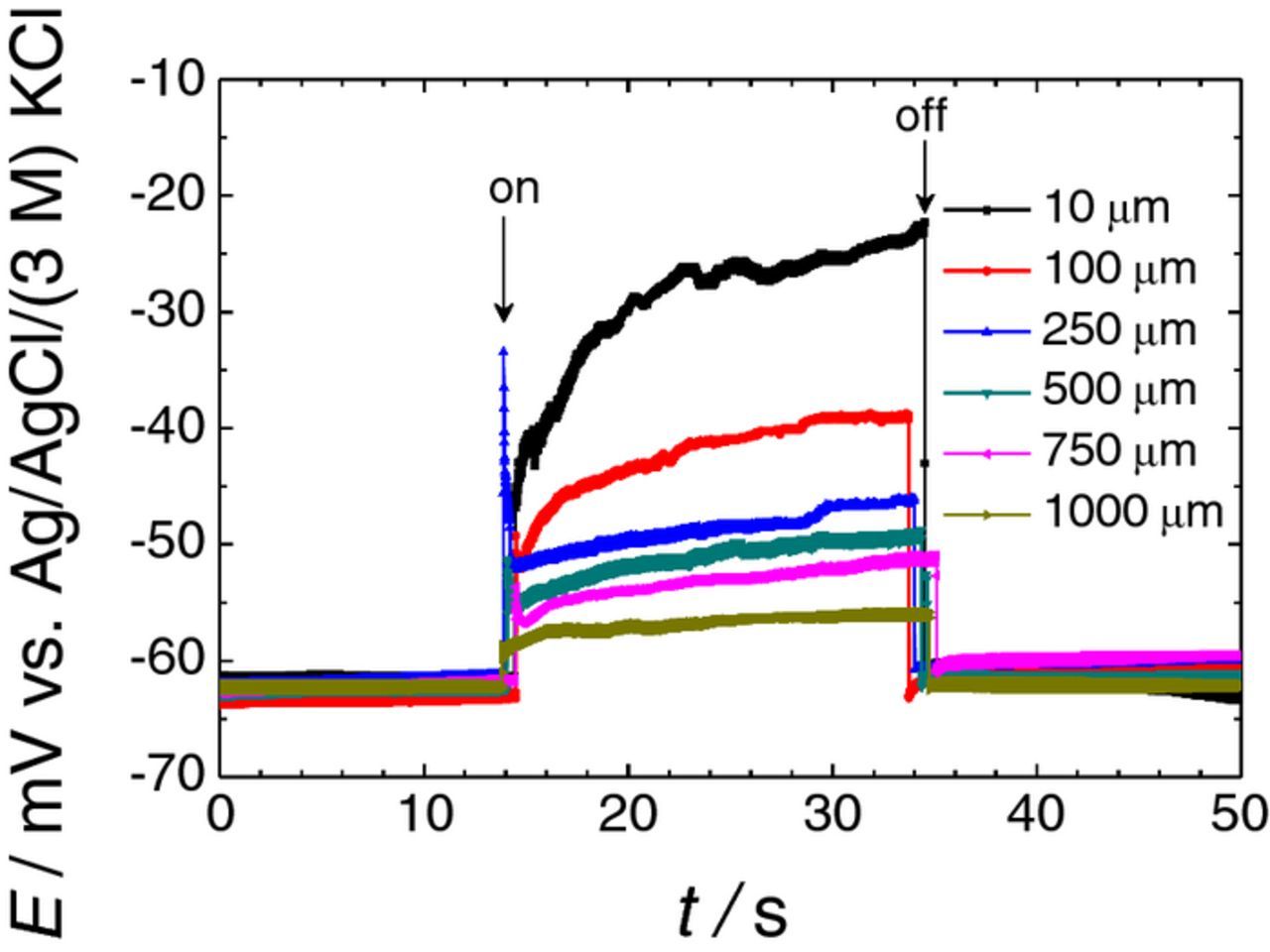
Figure 3. Effect of the distance between the ISME tip and the sample on the potential transients recorded by the Mg2+ ISME due to the galvanic coupling of the AZ63-Fe pair immersed in 0.001 M NaCl. The ISME was placed over the center of the AZ63 strip. Separation between AZ63 and Fe strips: 1.5 mm. The arrows indicate the times of electrical connection ("on") and disconnection ("off") of the two metals.
Conductivity of the electrolyte
A second factor expected to affect the electrical field is the conductivity of the electrolyte. Indeed, when it comes to galvanic corrosion, it is generally known that the electrical field is zero in the bulk of the metals because of their high electronic conductivity, and the current lines are formed in the metal/electrolyte phase boundary. Figure 4 shows the constant tip height measurements recorded over the AZ63-Fe galvanic system in solutions of different concentrations of NaCl. Similar to the experiments described in Tip-sample distance section, the tip was placed above the center of the Mg alloy sample, although using a fixed tip-sample distance of 50 μm. The concentration of the test electrolyte was varied from 0.1 mM to 1 M NaCl between the measurements. Potential jumps were experienced by the ISME signal when establishing the galvanic coupling for all the NaCl concentrations. Yet it is readily observable that the potential jumps became smaller with increasing concentrations of test electrolyte, correlating with smaller contributions of the ohmic drop. Therefore, it is observed that the cell time-constant involving the electrolyte resistance and the double layer capacitance contribute to the electrical field effect as reported by Trinh et al.25 In fact, it has been demonstrated that the potential difference between a working electrode and a reference electrode located in the bulk of the electrolyte is composed by a surface overpotential due to the electrode reaction, a concentration overpotential associated with concentration changes in the solution adjacent to the working electrode and an ohmic potential drop between the two electrodes.26 Accordingly, the decrease observed in the size of the potential jumps with the increased electrolyte composition results from smaller concentration variations in the solutions near the measuring probe.
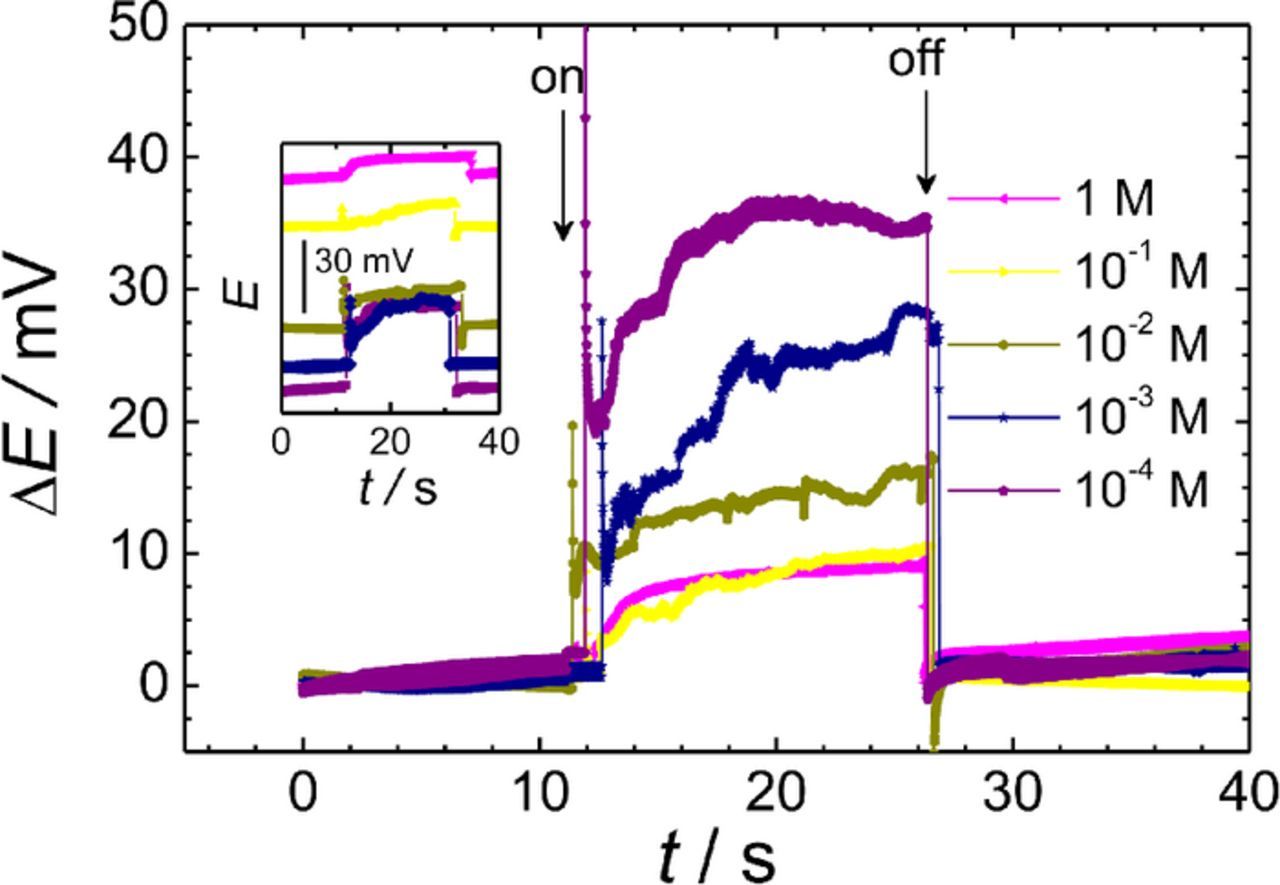
Figure 4. Effect of the electrolyte concentration on the potential transients recorded by the Mg2+ ISME due to the galvanic coupling of the AZ63-Fe pair immersed in NaCl. The ISME was placed over the center of the AZ63 strip. The curves were shifted along the potential axis for easier comparison, although the inset shows the original recordings. Separation between AZ63 and Fe strips: 1.5 mm; distance between the probe and the sample: 50 μm. The arrows indicate the times of electrical connection ("on") and disconnection ("off") of the two metals.
It must be noticed that the vertical axis in Figure 4 do not display real potential values with respect to the reference electrode, but have been shifted along the potential scale by subtracting the initial potential values recorded while the galvanic pair was disconnected. That is, the measured potential-time plots do not reach the same potential values at the beginning of the experiment. One reason is that the corrosion rate of the magnesium alloy is sensitive to changes in the concentration of the aggressive environment, and therefore a higher Mg2+ level was sensed by the probe in more concentrated test solutions. Nevertheless, since the exposition to the saline environment was less than 1 minute in each experiment, the most important reason should be insufficient selectivity of the ionophore cocktail to sodium ions. The selectivity coefficient was determined using the separate solution method and was found to be log KpotMg, Na = −2.5, which is in excellent agreement with the value reported for this ionophore.27 In this graph, the relative potential change in each experiment was plotted to facilitate a more direct comparison of the potential jumps monitored from each solution, whereas the actual potential transients are shown in the inset. From the inspection of Figure 4 it can be concluded that the increase in the conductivity of the corrosive medium reduces the magnitude of the electrical field effect. However, this conclusion should be received with some caution because the selectivity of the ion selective electrode to the cations in the medium must also be considered. In addition, the internal resistance of the ISME is also a critical factor to take into account. Although the resistance of ion selective microelectrodes has decreased in the solid contact design, the investigator must be aware that the resistance of solid contact ISME depends mainly on the height of the cocktail column between the very end of the solid contact and the orifice of the micropipette. Given the geometry of the tip (the shape of the column), the size of the orifice cannot be reproduced with complete satisfaction, and minimization of the electrical field effect should be sought in another way.
Distance between the metals in the galvanic pair
The effect of the distance between the two metals, namely the magnesium alloy AZ63 and pure Fe, was investigated next. Four sample arrangements were prepared with different separations between the metals. Similarly to the above experiments, the ISME was placed above the center of the AZ63 sample at a fixed tip-sample distance of 50 μm, and 1 mM NaCl solution was employed as test electrolyte. The experimental potential-time plots shown in Figure 5 were recorded for galvanic pairs with separations of 1.5, 4.2, 7.1, and 15.9 mm between the metals. It was found that the magnitude of the electrical field increased as the distance between the metals was larger, in accordance with the larger ohmic drops involved. In the case of the sample with a separation of 15.9 mm, the potential jump corresponds approximately to a miscalculation of 3 orders of magnitude according to the calibration curve of the ISME that was previously determined using standard solutions in the absence of perturbation due to the electrical field. Unfortunately, even the potential jump observed at the smallest separation of 1.5 mm was 30–35 mV, whereas at this distance, the products of one half-cell reaction can affect the other, thus hindering the separate investigation of each half cell reaction when desired.
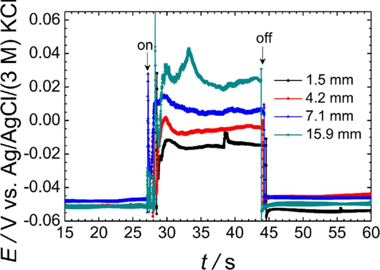
Figure 5. Effect of the separation between the metals on the potential transients recorded by the Mg2+ ISME due to the galvanic coupling of the AZ63-Fe pair immersed in 0.001 M NaCl. The ISME was placed over the center of the AZ63 strip. Distance between the probe and the sample: 50 μm. The arrows indicate the times of electrical connection ("on") and disconnection ("off") of the two metals.
The nature of the galvanic pair
The impact of the galvanic coupling itself on the electrical field developed in the system was next investigated by coupling magnesium with different metals. Due to the availability of wires for each metal including magnesium, the samples were prepared using circular cross sections of 0.125 mm diameter wires spaced 6 mm apart. The new sample series contained pure Mg wires as anode, and zinc, aluminum, iron or copper cathodes. The test solution was 1 mM NaCl chloride solution. As before, the ISME tip was placed over the center of the Mg wire, with a vertical tip-sample distance of 50 μm. For reasons of comparison, the graphs of the monitored potential were shifted along the potential axis by subtracting the initial values from each curve. Table I lists the average heights of the potential jumps recorded for each metal combination upon connection/disconnection of the galvanic coupling. In general, the potential jumps were smaller than previously reported using the larger AZ63 magnesium alloy and Fe samples due to a geometric factor, namely the smaller size of the electrodes. It has been reported that the influence of the size of the substrate cannot be neglected in SECM experiments, and smaller electrical cross-talk effects should be expected using smaller electrodes.25 It is observed that the nature of the counter metal influenced the magnitude of the potential jumps according to its position in the galvanic series. Therefore, the smallest potential jump was measured for the Mg-Zn pair, and the largest for the Mg-Cu pair. Another outcome of these measurements was that the size of the sample also had an impact on the magnitude of the potential jump produced by the galvanic coupling.
Table I. Potential jumps measured at the Mg-ISME due to the electrical connection between magnesium and other metals during immersion in 0.001 M NaCl. Separation between Mg and Fe wires: 6 mm. The ISME was placed over the center of the Mg wire at 50 μm height.
| Galvanic pair | ΔE / mV |
|---|---|
| Mg-Zn | 2 |
| Mg-Al | 4 |
| Mg-Fe | 6.5 |
| Mg-Cu | 10 |
Distance between the ISME and the reference electrode
In the usual SECM laboratory practice the placement of the reference electrode in the small electrochemical cell is incidental, the only consideration is to leave the scanned area free for movement of the probe. In the experimental methodology employed in this work, the magnitude of the electrical field effect on the ISME response was conducted by keeping the tip stagnant in the cell at a certain height above the samples of Mg or AZ63. In this arrangement, the distance between the reference and the ion-selective electrodes could also be adjusted by the operator. In addition, the small size of the reference electrode allowed this distance to be adjusted to an accuracy of 1 mm. Measurements were performed with the 1 × 1 mm2 AZ63-Fe sample with a 1.5 mm separation in 1 mM NaCl. The average values of the potential jump with respect to the distance between the reference electrode and the ISME are plotted in Figure 6. As it can be seen, the closer the reference to the ISME, the smaller the potential jump. This is due to the fact that in the presence of an electrical field, the potential measured between the ISME and the reference electrode consists of the following terms:
![Equation ([1])](https://content.cld.iop.org/journals/1945-7111/165/5/C270/revision1/d0001.gif)
where ΔE is the measured potential difference, EM and ER are the potential of the measuring and reference electrode, respectively, and φM and φR are the local potentials in the electrical field at the measuring and reference electrodes. The first term is the Nernstian response; the second term is the field potential difference, an unwanted component of the cell voltage originating from the different potentials detected by the electrodes in different places. As the reference electrode got closer to the ISME, the difference between φM and φR decreased. The inset in Figure 6 provides an interesting comparison of the experimental curves obtained in the two limit distances considered. The red curve was taken with the reference electrode located 12 mm away from the AZ63 specimen, while the other was recorded with the closest possible position of the reference electrode to the ISME when their lateral bodies were touching each other. When both electrodes were placed together above the AZ63 sample, the potentiometric response was not affected by electrical field effects. On the other hand, when the reference electrode was located far from the AZ63 surface, the electrical field affected the two electrodes to a different extent, which showed up in the central portion (i.e., 20–40 s) of the red graph. Although the effect of the electrical field could not be seen in the black curve, the chemical change in the proximity of the AZ63 specimen is clearly visible. When the electrical connection was made, the galvanic pair was established; magnesium behaved as the anode of the pair, with a higher rate of dissolution. The diffusion of the Mg2+ species from the surface of the sample to the solution (i.e., toward the ISME) evolved throughout the measurement even in this brief period of time. Besides, this driving tendency for the magnesium dissolution was maintained after the galvanic pair was disconnected, albeit with a smaller slope. Evidently, when the galvanic connection ceased, the anodic reaction slowed down, so that the flux of the Mg ions was also smaller. This reproducible characteristic was sufficiently resolved during previous experiments, so it can be concluded that potential jumps also produce artifacts in the measurement at short times after performing the connection-disconnection operation.
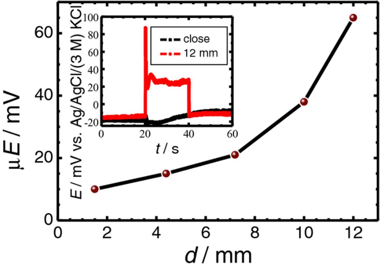
Figure 6. Effect of the separation between the ISME and the reference electrode on the potential transients recorded by the Mg2+ ISME due to the galvanic coupling of the AZ63-Fe pair immersed in 0.001 M NaCl. The ISME was placed over the center of the AZ63 strip. Separation between AZ63 and Fe strips: 1.5 mm; distance between the probe and the sample: 50 μm. The inset shows the potential transients recorded for the distances between the two electrodes indicated in the graph.
Measurements with an open micropipette
The results obtained in the previous section allow us to consider that the use of a double barrel arrangement for the ISME can be a good procedure to suppress electrical field effects in potentiometric SECM measurements. In this way, no single fixed reference electrode will obstruct the translation path of the ISME, but will follow it throughout the scan. Next, the potential contribution due to the electrical field sensed by the ISME will be the same at each point. As result, the last term of Eq. 1 will become negligible, and only the Nernstian response will be monitored even during galvanic coupling. To test this hypothesis, a micro-reference electrode was fabricated into a non-silanized micropipette. The micropipette was filled with 0.1 M KCl solution, and a 0.5 mm diameter chlorinated silver wire was inserted in its lumen. The potential values were measured with respect to the reference electrode previously employed. The distance between the passive probe and the reference electrode was approximately 1 cm.
Line scans were recorded by translating the ISME parallel to the AZ63-Fe sample (i.e., constant height of 50 μm, fixed Z position) in 1 mM NaCl solution. Successive recordings were taken by passing over the connected or disconnected galvanic pair system. The scan rate was 20 μm s−1, and the step size was 20 μm. Typical plots for each electrical condition are shown in Figure 7. The red-colored line scan was monitored while the Mg and the Fe specimens were electrically connected, while the blue-colored line scan was recorded during the spontaneous corrosion of the two metals. The approximate positions of the metals are indicated in the plot drawing gray rectangles in the background.
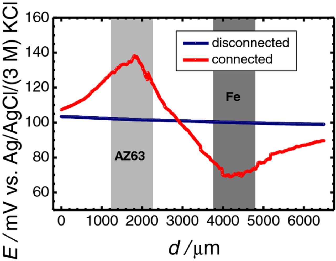
Figure 7. Line scans recorded with a Ag/AgCl micro-reference electrode translating at 50 μm height across the AZ63-Fe pair immersed in 0.001 M NaCl. Electrical condition: (blue) disconnected, and (red) galvanic connection. Separation between AZ63 and Fe strips: 1.5 mm; distance between the probe and the sample: 50 μm; scan rate: 20 μm s−1; step size: μm. The approximate locations of the metals are indicated by the grey-colored rectangles.
In potential values recorded while the galvanic pair was disconnected, no changes were observed (blue curve) as the tip moved from the resin to the metals. Thus, the shape and position of the metals could not be distinguished from the surrounding resin in this case. Since local anodes and cathodes are developed on the surface of both AZ63 and iron during spontaneous corrosion of metals, current lines must be established in the electrolyte adjacent to the metals. However, these current lines should have a much lower range that those of the galvanic coupling condition, and this passive probe could not detect them.
In contrast, the red-colored line showed large potential changes as it approached any metal, namely a positive potential change over the anodic area of the AZ63 sample, and a symmetric but negative change above the cathodic area of the iron. Since this passive probe has no selectivity for ionic species, this is evidently a measure of the electrical field. This principle is exploited in the scanning reference electrode technique (SRET),28,29 and the scanning vibrating electrode technique (SVET).30 This experiment confirmed the hypothesis that if the reference electrode is at approximately the same location as the ISME for each measurement point during the scan, the potential sensed by the reference electrode follows the change in the electrical field experienced by the ISME, and its effect can be neglected.
Measurements with double barrel probes
The combined Mg-ISME and Ag/AgCl micro-reference probe shown in Figure 1 was used to demonstrate the benefit of application of double barrel electrode assemblies for the potentiometric SECM investigation of galvanic pairs. The 1 × 1 mm2 AZ63-Fe galvanic pair with 1.5 mm separation between the metals, immersed in 0.001 M NaCl solution, was used as a model system. Potentiometric line scans were recorded above the electrically connected sample with the probe translating at a 50 μm distance from it. The scanning rate was 20 μm s−1, and the step size was 20 μm. The potential of the Mg-ISME barrel was first measured with respect to the conventional reference electrode placed in the bulk of the electrolyte, approximately 1 cm away from the sample. Subsequently, the measurement was repeated but using the micro-reference electrode inside the double barrel probe. Figure 8 exhibits the differences between the two measurements. The translation of the double barrel probe was initiated from a position above the resin, the probe then passed over the iron strip, continued moving over the resin separating the two metals, then passed across the AZ63 sample, and was finally stopped above the resin on the other side of the magnesium alloy. The approximate positions of the metals are indicated in the figure. Convection effects caused by the evolution of hydrogen gas accounted for the noisy signals recorded here. The black horizontal line drawn at ca. −0.07 V indicates the lower detection limit of the ISME. An anomalous behavior is displayed by the line scan recorded with the traveling ISME when using the external reference electrode (cf. blue plot in Figure 8). It must be observed that the potential jumped approximately 34 mV when the galvanic coupling was established, analogously to what happen in the experiments reported above. Therefore, for a more direct comparison of the potential transients, this 34 mV potential jump was subtracted from the measured value at every point, transforming the curve with respect to the values that were measured at the right side of the Mg sample, where the jump was actually observed. To avoid further complications the scan was started from the opposite side of the iron sample. During its initial passage from the resin toward the iron strip, the ISME recorded a non-zero signal for Mg2+ ion that is above the lower limit of detection of ca. −0.07 V. The signal shifted to more negative potentials, finally crossing below the horizontal line at ca. −0.07 V as it approached the iron strip. Signals of even more negative potential were recorded during translation above the iron sample, and only returned to more positive potential values after the probe had abandoned the iron strip. This behavior would imply that Mg2+ ions have not diffused to reach the electrolyte volume adjacent to the iron strip, however, some Mg2+ ions had reached the resin on the opposite side of the iron sample with respect to the position of AZ63. This trend can only arise from some artifact in the measurements. Therefore, in addition to the unwanted effects of the electrical field described in the previous sections, the electrical field effect also produced a shift of the measured potential in the ISME toward more negative values above the cathodic area, while a change in the opposite direction, (i.e., toward more positive values) occurred above the anodic area. In contrast, the red-colored scan line initially showed values close to the lower limit of detection above the resin, and remained almost constant above the iron strip regardless the convection effects originating from gas evolution on the metal. This implies that the electrical field above the cathodic area did not produce any significant effect on the potential measured using the double barrel electrode probe. Potential values related to the magnesium dissolution were subsequently recorded when the moving probe approached the AZ63 sample, and decreased abruptly after abandoning the metal into the resin on the opposite side. Since the blue line scan was recorded first, the probe had passed over the same positions about 6–7 min later during the red line scan and therefore, a more extensive corrosion of the magnesium alloy occurred for the latter. However, the height of the potential peak recorded using the double probe electrode is 18–20 mV less positive than the peak recorded using the external reference electrode. As the galvanic connection was maintained throughout the experiment, one could not expect a deceleration of the Mg dissolution from the AZ63 sample within the time scale of the experiment. Therefore, it can be concluded that this reported difference was due to effect of the electrical field. In addition, the peak in the red curve was narrower than for the line scan with the external reference, implying that the electrical field was sensed from large distances even in short times, long before Mg2+ ions could diffuse such distances. A similar large-distance effect of the electrical field was also observed in Figure 3 for 1 min exposure time when the ISME was located 1000 μm away from the sample. That is, although the electrical field could be sensed at that distance, however, the Mg2+ species could not have reached there. Finally, the red-colored line scan returned to the potential values typical of the bulk electrolyte in a faster trend that for the line scan in blue, and then remained stable above the resin.
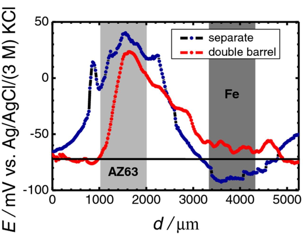
Figure 8. Line scans recorded with the novel double barrel probe containing a Mg-ISME and a Ag/AgCl micro-reference electrode while translating at 50 μm height across the AZ63-Fe galvanic pair immersed in 0.001 M NaCl. Reference electrode: (blue) external reference electrode in the bulk of the electrolyte; and (red) the internal micro-reference electrode inside the double barrel probe. Separation between AZ63 and Fe strips: 1.5 mm; distance between the probe and the sample: 50 μm; scan rate: 20 μm s−1; step size: μm. The horizontal line drawn for E ≅ −0.07 V vs. Ag/AgCl/(3 M) KCl indicates the lower limit of detection of the Mg-ISME. The approximate locations of the metals are indicated by the grey-colored rectangles.
Conclusions
In this study we have characterized the different factors that affect the magnitude of the electrical field produced in the electrolyte during galvanic corrosion. It has been shown that the distance between the reference electrode and the ion selective probe produces the greatest impact for the appearance of electrical field effects, whereas the other factors cannot be adjusted without compromising the resolution of the technique.
The design, construction and characterization of a double barrel assembly containing an internal reference electrode in addition to the ISME were described. The combined probe yields more reliable data than the conventional single ISME. The potentiometric SECM operation using this new probe configuration is expected to contribute significantly to the investigation of the corrosion of magnesium and magnesium alloys under both galvanic coupling and anodic polarization conditions.
Acknowledgments
D. Filotás expresses his greatest gratitude to the ERASMUS+ program for the financial support of a 2-month mobility grant to the University of La Laguna. B.M. Fernández-Pérez is grateful to the Canarian Agency for Research, Innovation and Information Society (Las Palmas de Gran Canaria, Spain) and the European Social Fund (Brussels, Belgium) for a research contract. Financial support by the Spanish Ministry of Economy and Competitiveness (MINECO, Madrid) and the European Regional Development Fund, under grant CTQ2016-80522-P, The National Research, Development and Innovation Office (Budapest, Hungary) under grant K125244, and the "Environmental industry related innovative trans- and interdisciplinary research team development in the University of Pécs knowledge base" under SROP-4.2.2.D-15/1/Konv-2015-0015 project, is gratefully acknowledged.
ORCID
R. M. Souto 0000-0001-9429-5513