
Abstract
Bilayer coatings consisting of a  inner layer and a
  outer layer were made on copper substrates
  and the photoelectrochemical properties of the derived bilayered photoelectrodes for corrosion protection application was investigated and compared with the performance of our previously studied
  bilayered photoelectrodes coating for similar applications.
  and
and  sols were used for preparing the coatings. Investigations on the charge storage capacity of the two different bilayered coatings revealed that the
  system is capable of storing higher charge at less negative applied potentials, i.e.,
  vs SCE, whereas, the
  system stores higher charge at more negative applied potentials, i.e.,
  vs SCE.
Export citation and abstract BibTeX RIS
Copper has been proposed as the ideal material for construction of canisters to be used for the disposal of spent nuclear fuels because of its outstanding corrosion resistance, ease of fabrication, abundant availability, and overall cost-effectiveness. For these reasons, extensive research has been pursued for assessment of suitability of copper for these same purposes and, therefore, corrosion protection of copper in the conditions prevailing underground becomes a matter of concern because the passive and protective copper oxide layer does not form when the oxygen potentials are very low. In this context, cathodic protection offered by  in the presence of ultraviolet (UV) light could be envisaged as appropriate. There have been substantial efforts to exploit the photocatalytic applications of nano
  in all fields that it is predicted to become a part of every individual's life in a few years. One of the most promising applications that has stimulated considerable interest in the recent past is its use as a photoanode for corrosion protection of metal and steel substrates. The working principle of photoaided cathodic protection is that when a metal coated with a thin layer of
  is exposed to UV irradiation,
  -hole pairs are created in the
  layer. The photogenerated electrons can be transferred to the metal substrate thereby making its electrode potential more negative than its corrosion potential. The main advantage of this method is that the photoanode, i.e.,
  in this case, does not get consumed during the process of corrosion protection, unlike a sacrificial-type cathodic protection. However, in the case of the applicability of
  coatings for corrosion protection of copper under subterranean conditions, there would be no light available for such a purpose. But this problem is not a serious one as the containers would hold high-level nuclear waste and the gamma radiation being emitted from them could itself be visualized as an in situ source of UV illumination, provided suitable radiation converters are incorporated in the protective
  -based coating. The exact mechanism of corrosion protection offered by a
  coating on metal/steel substrate in presence of UV illumination has been discussed in detail in Refs. 1–4.
One of the inherent disadvantages of using a plain  coating for anticorrosion applications is that the photoeffect ceases to be operative once the UV illumination stops shining on the
  -coated substrate. A possible method for solving this problem would be to couple another semiconductor like
  whose conduction band (CB) level is lower than that of
  5 so that the photogenerated electrons could be transferred from
  to
to  and the coupled semiconductor, i.e.,
  , should be capable of storing and releasing the photogenerated electrons. Another candidate semiconductor that could be coupled with
  would be nano
  . There are several reports on the use of
  electrodes for electrochromic windows, where the reversibility for lithium insertion in
  was used for transmissive electrochromic devices.6, 7 In addition, a recent report describes the application of hierarchically mesostructured
  for use in solar cells,8 where the active component is nanometric ceria using a constructed organic-dye-free solar cell. The reason for this is that the bandgap of nanometric ceria was found to have shifted by
  when compared to that of
  . In view of the potential applications of nanoceria, the present investigation was carried out with an objective to measure the photoelectrochemical properties of
  bilayer electrodes on copper substrates and to find out if such electrodes possess the desirable properties of an efficient photoanode for corrosion protection. The results obtained are compared with the performance of the
  electrode for the same application.
Experimental
Synthesis
A commercial 
 sol solution (pH 7.0) supplied by Nihon Parkerizing Co., Ltd., Japan, was used as the source of
  . The average crystallite size of
  in the solution was
  . Ceria nanoparticles were synthesized using a low energy wet chemical synthesis technique known as microemulsion, the details of which are given as follows. The microemulsion system consists of surfactant sodium bis(2-ethylhexyl)-sulfosuccinate (AOT), toluene, and Millipore DI water. All the chemicals were purchased from (Aldrich, Inc.). AOT was dissolved in toluene and
  aqueous cerium nitrate solution was added. The mixture was stirred, and hydrogen peroxide was then added dropwise. The detailed synthesis procedure is explained in Ref. 9. The reaction was carried out for
  and then the reaction mixture was allowed to separate into two layers. The upper, pale yellow layer was toluene-containing nonagglomerated ceria nanoparticles and the lower layer was the aqueous phase. The morphology of
  nanoparticles was studied by high resolution transmission electron microscopy (HRTEM) using a Philips HRTEM operated at
  accelerating voltage. Figure 1 shows the HRTEM image of the synthesized cerium oxide nanoparticles.
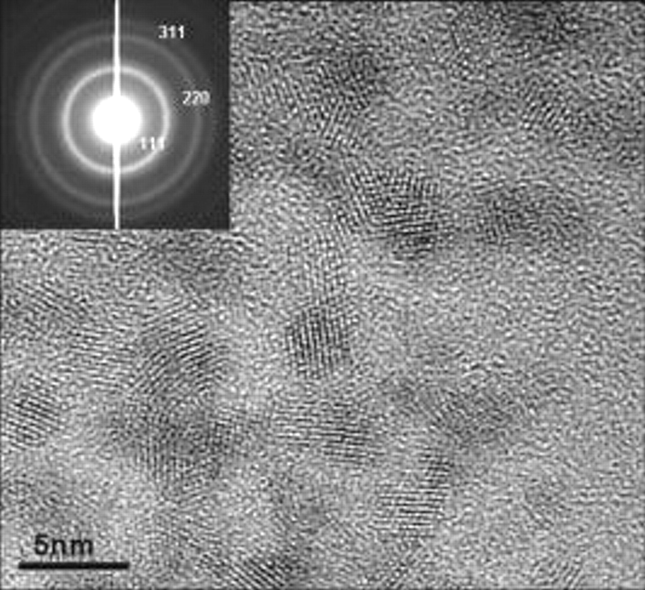
Figure 1. HRTEM image of nanoceria particles (size  ). (Inset shows the SAED pattern indicating the fluorite structure of nanoceria sample.)
Copper specimens of dimensions  were used as the substrates. The copper plates were polished to a mirror finish with
 prior to coating and thoroughly degreased in acetone for
  in an ultrasonic cleaner, which were subsequently used as substrates for coating the photoanode material. The photoanode coating consisted of two layers, the first one being
  and the outer layer
  .
.  coatings on copper coupons were made using a dip coater, and the coating thickness was calculated using the weight difference of coupons before and after coating. The coating thickness was approximately
  on each sample.
  coatings on the
  layer were made by the spin-coating technique in order to achieve a thickness of
  for the
  layer. The total thickness of the photoanode was measured to be approximately
  . The bilayered photoelectrode coating on the copper substrate was co-fired at
  for
for  in a
in a  atmosphere to obviate oxidation of copper during heating. The heat treated coupns were subsequently subjected to photoelectrochemical characterization.
Photoelectrochemical characterization
Electrochemical characterization was carried out by measuring the open circuit potential (OCP) of the samples under dark and UV illuminated conditions with reference to a saturated calomel electrode (SCE). A deaerated 0.3% NaCl solution was used as the electrolyte unless otherwise mentioned, and a Pt strip was used as the counter electrode for polarization measurements. In order to simulate the conditions prevailing underground, a deaerated atmosphere was created during the electrochemical studies by purging the electrolyte solution with  (purity, 99.9%). A
  Hg lamp was used as the source of UV illumination. The light first passed through an optical filter (UV-34, Kenko), which mostly
  allowed only light of wavelengths greater than
  . After this light passed through a quartz window, it was then made to fall on the coated side of the copper plate. A transparent electrochemical cell made of acryl fitted with a quartz window on one side was used. The sample was fixed on the opposite side with the aid of an O ring. A more detailed description of the experimental details is given in Ref. 10.
For impedance measurements, the same conditions with respect to atmosphere and electrolyte as used for the OCP measurements were maintained. Impedance was measured as the current response to a superimposed ac signal of amplitude  with a frequency ranging from
  up to
up to  at various applied potentials provided by a potentiostat, model 2090 HS supplied by Toho Techniques Research, Japan. After a preliminary analysis of the impedance data obtained for various applied potentials as a function of frequency, it was found that at lower frequencies
  , the system showed a capacitive behavior, and this was ascertained to be arising from the bilayer electrode coating. Hence, for measurement of the capacitance of the coating, the impedance was measured at potentials ranging from
  down to
  in steps of
  at a low frequency of
  . The system was kept for
  at any applied potential before measurement, as it was verified that a constant current state was reached at
  after application of potential.
Results and Discussion
As a first step, the response of the OCP of different samples to UV illumination was studied and their time evolution observed after exposure to UV source and after cutting it off.
Figure 2 shows the time evolution of the OCP on exposure to UV illumination for  . It can be seen that there is an initial p-type effect (OCPs instantaneously becoming more positive) on exposure to UV light. But after sometime, the electrode potential slowly reverts back to negative values. Nevertheless, the values do not become more negative than
  whereas, in the case of a plain
  coating (also included in Fig. 2), though the same initial p-type effect is observed, after some time, the electrode potentials slowly become more negative and finally reach values of
  , which is the photopotential of
  . The initial p-type effect is due to the presence of a thin layer of copper oxide
  present between the copper and the semiconductor oxide coating, that could have formed due to the interaction of the copper surface with the water-based sol solution during heat-treatment.
  and CuO are both p-type semiconductors with bandgap equal to 2 and
  , respectively, and their presence adversely affects the normal n-type photoeffect in
  as shown in Fig. 2. The copper oxide layer can be reduced by photogenerated electrons from
  ,10 but the photoeffect in
  , though capable of reducing the copper oxide layer, cannot make the OCP reach large negative values like
  (cf. Fig. 2). Hence, there is a necessity to include
  in the photoanode containing
  . But since the electrical conductivity of
  is greater than that of
  , the design of a bilayer coating was thought of, where the photoeffect could be generated by an outer
  layer, from which the photogenerated electrons could be passed on to the substrate via an intermediate
  layer, whose electrical conductivity was substantial to facilitate charge transfer. In addition, since
  is also capable of exhibiting multiple valence, it is expected to store charge in the form of photogenerated electrons according to Eq. 1, which will sustain the photoeffect even after cessation of UV illumination, by releasing the stored electrons to the substrate

where  or Li and
  .
.
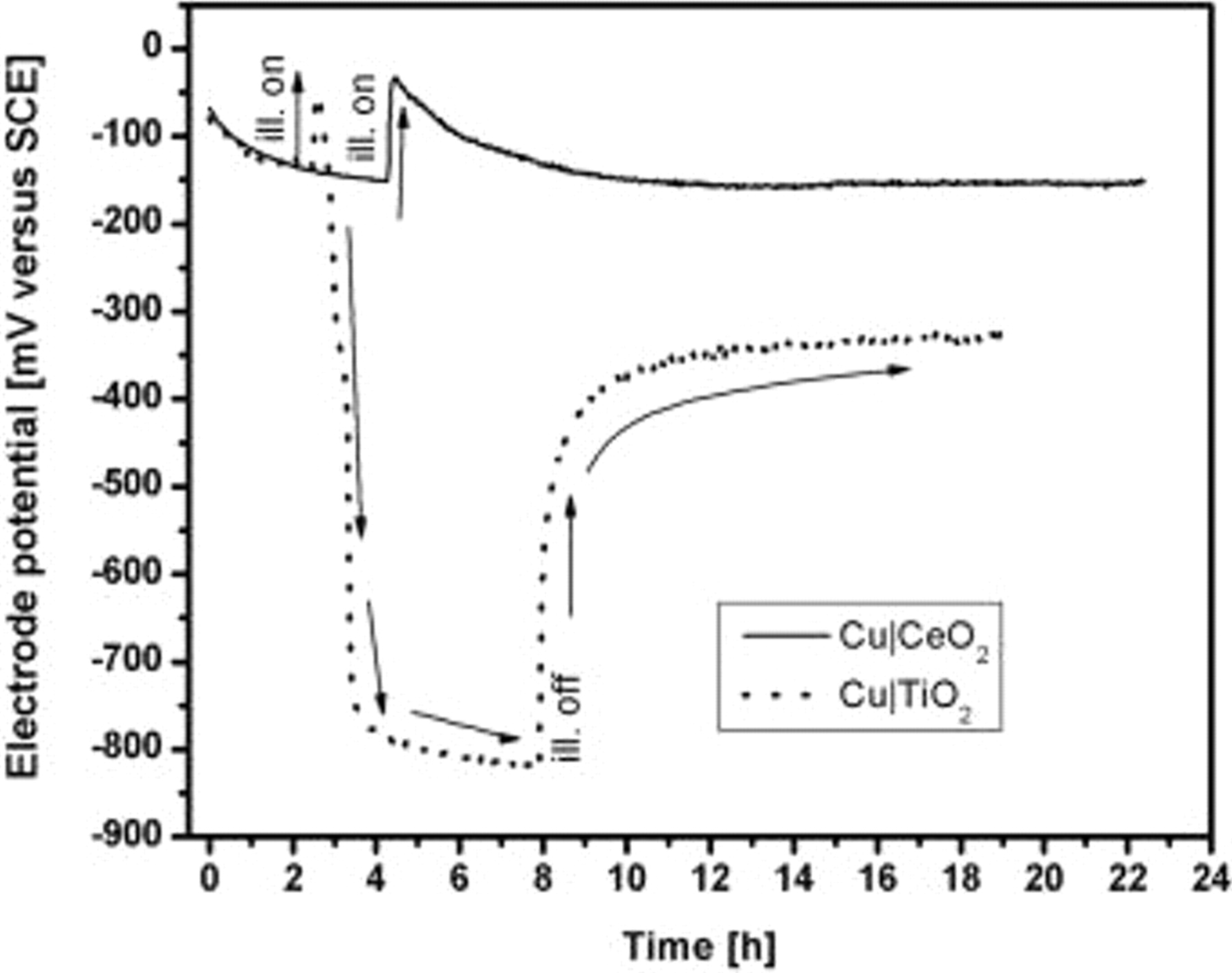
Figure 2. Comparison of the response of electrode potentials to UV illumination for  and
and  .
.
Figure 3 depicts a comparison of the response of the OCP response on exposure to UV illumination for the  which is also compared with that of
  (taken from Ref. 10). It can be seen that, though both the profiles are comparable with respect to the absolute values of the photopotentials, the recovery of the electrode potentials after the source of UV illumination has been cut off, differs to a slight extent. The electrode potential after the stopping of illumination is more negative for the bilayer electrode containing
  than that obtained in the case of
  and remains at such values for a longer period of time. This clearly indicates that the charge-storage property of
  is different from that of
  , which result is expected. The charge-storage property could be quantified by measuring the capacitance as a function of applied voltage, which was carried out by measuring the impedance at low frequencies such as
  , with varying applied potentials.
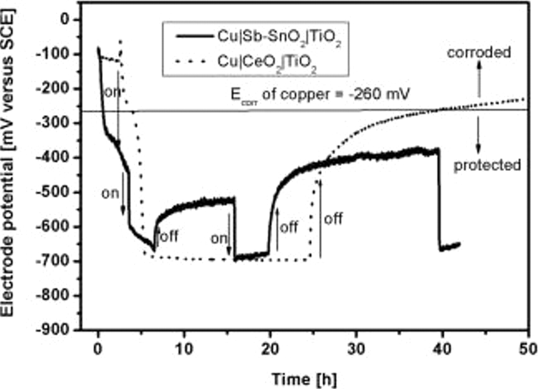
Figure 3. Time evolution of electrode potential and its response to UV illumination compared for  and
and  .
.
Figure 4 shows the Bode plot for the sample polarized at  vs SCE. An equivalent circuit corresponding to the configuration given in Fig. 5a was assumed for the analysis of the impedance data. The impedance information can be divided into three distinct regions.
  represents the solution resistance (appears at very high frequencies);
  are those from the high frequency response (due to electrode solution interface);
  are the resistance and capacitance components of the low frequency response (due to the semiconductor oxide coating). The value of each component was determined from the absolute value of the impedance determined at specific frequencies where only one of the components would be a major contributor to the total impedance, neglecting the effect due to others. The calculated data assuming the equivalent circuit fitted well with the measured data and is shown as a solid line in Fig. 4.
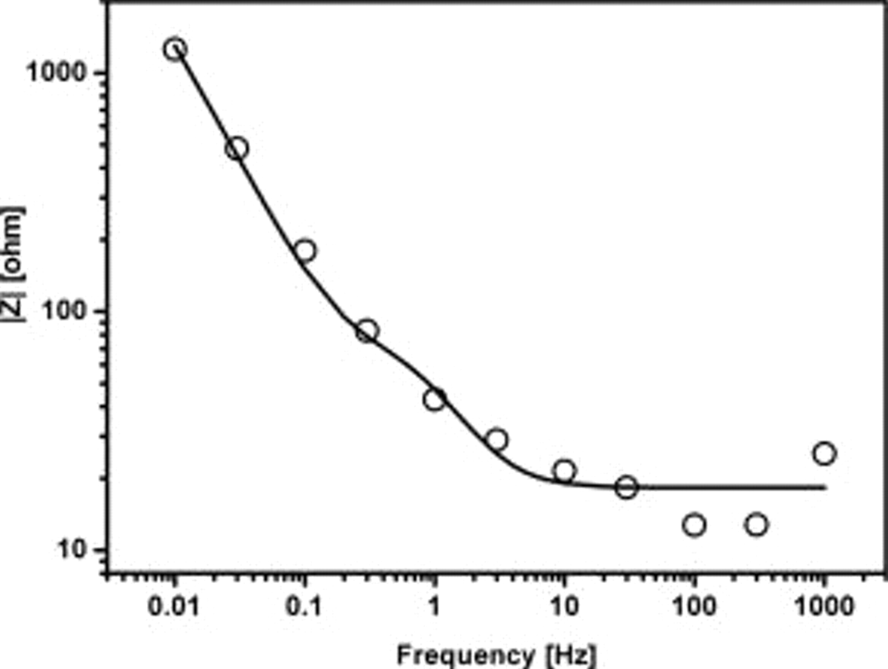
Figure 4. Impedance measured as a function of frequency for the  HT Cu∣bilayered electrode at an applied potential of
  vs SCE; solid line is the curve fitting according to equivalent circuit given in Fig. 5a.
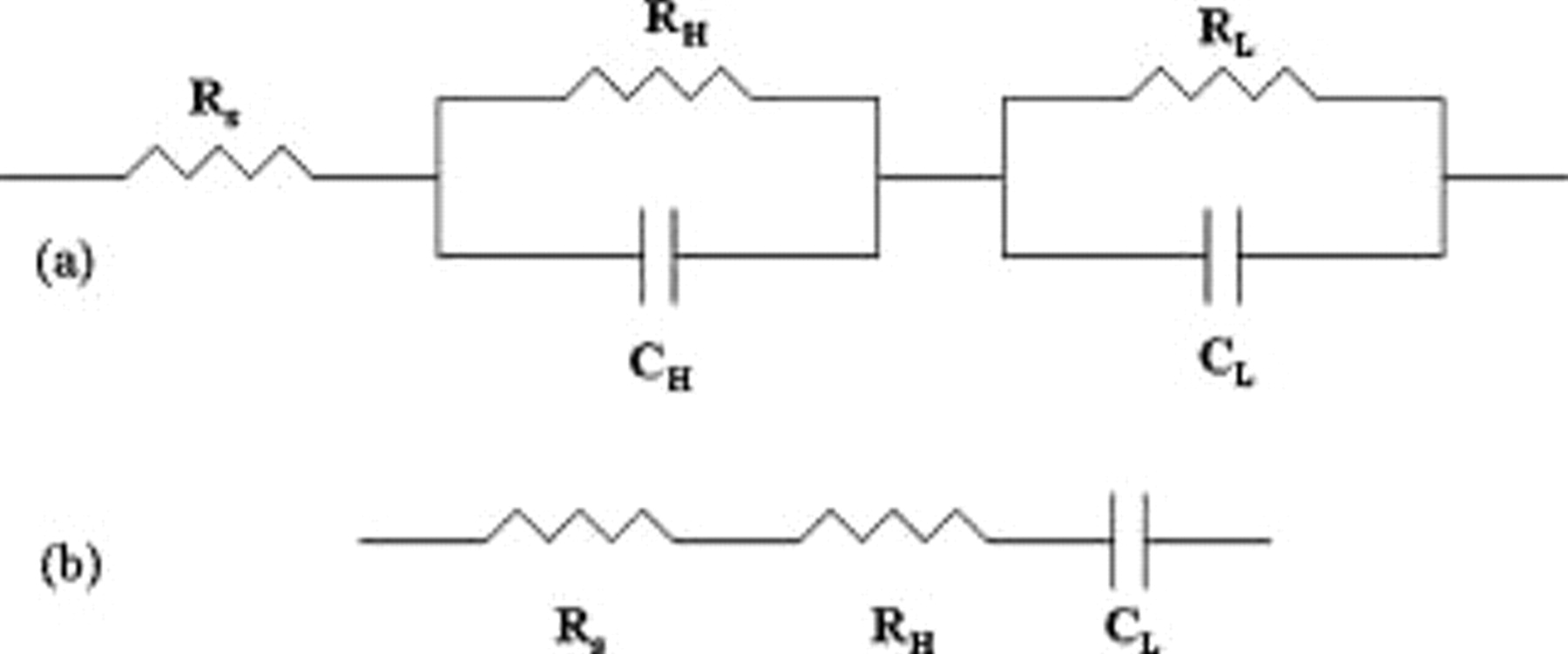
Figure 5. (a) Equivalent circuit proposed conforming to the measured impedance data and (b) reduced circuit at low frequencies.
From the impedance measurements at  for various applied potentials, the capacitance of the bilayer coating was determined at each applied potential at this frequency assuming the equivalent circuit shown in Fig. 5b and plotted in Fig. 6. Figure 6 shows a comparison of the capacitance for
  ,
,  , and
, and  samples measured as a function of the applied electrode potential vs SCE. The
  electrode obviously stores less charge throughout the range of applied potentials of measurement when compared to the other two electrodes. This is due to the fast charge recombination (electron-hole) on the
  surface. However, when one compares the charge-storage property of
  and
and  , it is seen that
  exhibits a constant charge, i.e.,
  stored over potentials from
  down to
  and then there is a sudden increase in the amount of charge stored for still lower potentials. The large values of capacitance at
  corresponds to the one electron reduction from
  to
to  followed by subsequent reduction to
  as indicated by the sudden increase in the capacitance beyond
  . The high capacitance values of
  at
at  confirm that when the electrode potential reaches the value of
  during illumination (photopotential), there is a charging up of the electrode. When the source of illumination is cut off, this stored charge is slowly discharged to the substrate such that a highly negative electrode potential of the substrate is still maintained.
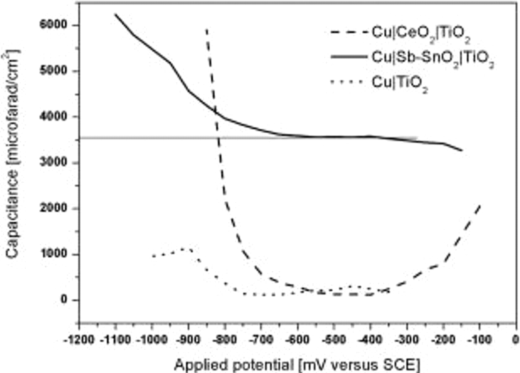
Figure 6. Capacitance as a function of applied potential for  and
and  .
.
In the case of  there is low charge ranging from
  stored at potentials from
  down to
  and then there is a sudden increase in the stored charge, which is even higher than that stored by the
  electrode at even potentials. This indicates that the reduction of
  to
to  takes place at a more negative electrode potential when compared to
  reduction.
It is desirable that the reduction of the multivalent species ( or
or  ) in the photoanode should take place at its photopotential, so that the photogenerated electrons can be transferred from
  and can be stored simultaneously. In view of this requirement, from the present study, it can be inferred that the
  electrode is preferable as a photoanode when compared to
  . However, the
  electrode could also be made more efficient, if the photopotentials can be made around
  , where an in situ reduction of Ce takes place and the charge can be reversibly stored and released to the substrate, thereby sustaining the photoeffect.
Conclusion
The present study was carried out to evaluate and compare the performance of  bilayered photoelectrode with
  . The photoelectrochemical properties were characterized by measuring the electrode potential response to UV illumination and the charge-storage capacity by impedance measurements as a function of applied electrode potential. The investigations revealed that
  bilayered photoelectrode showed good charge-storage capacity at the photopotential of
  . Nevertheless, the results also showed that if the photopotential of the electrode could be made
  or lower,
  bilayered photoelectrode is also capable of very high charge storage.
Acknowledgment
R.S. acknowledges the National Institute for Materials Science, Tsukuba, Japan, for financial support in the form of a fellowship.
National Institute for Materials Science assisted in meeting the publication costs of this article.