
Abstract
New types of antennas such as Substrate Integrated Waveguide (SIW) antennas are being used for high frequency applications. In this paper, the development of an array of novel slotted SIW epsilon near zero (ENZ) antenna is presented. Due to the limited fabrication facilities, the study is conducted in the 5 GHz band. The effective permittivity falls to zero at the cut off frequency of the waveguide. This impact is utilized to make an effective ENZ material in an ENZ super tunnelling waveguide. The design of 1 × 2, 1 × 4 antenna array is presented. The design of microstrip power dividers for feeding the array element is discussed. The presented antenna array achieve higher gain than the previously designed antennas. The prototype of the 1 × 4 SIW ENZ antenna array is fabricated and the measurement results are compared with the simulated studies. This work pertains to investigation on the array of SIW antennas for millimetre wave applications.
Export citation and abstract BibTeX RIS
1. Introduction
As of late, there has been a surge in the popularity of research surrounding metamaterials. Such materials are artificially designed to have properties that do not typically happen in nature. These properties are brought about by the materials permittivity, ε, and permeability, μ, values. This gives rise to a variety of different potential applications [1, 2]. However, metamaterials don't generally zero in on negative permittivity and permeability values; or even both values simultaneously. Materials with a permittivity of near zero are called epsilon near zero (ENZ). These engineered materials can deliver unconventional electromagnetic highlights. This, again, gives rise to a number of potentially exciting applications. The most famous of which is invisibility and cloaking devices [3–6]. While such science fiction concepts attract a lot of attention, ENZ materials have intriguing applications in a wide range of fields. ENZ materials have numerous uses in communication systems [7–10]. These uses include scaling down and streamlining of microwave segments, design of highly directive antennas, and phase pattern tailoring.
Engheta et al exhibit that utilizing two larger waveguides connected by an ultra-narrow waveguide channel area deliver a part that is successfully observed as an ENZ metamaterial [11]. Super-tunnelling happens in this segment where the wave propagates through the part with little reflection. Research in [12], the strategy proposed by Engheta et al is executed on a substrate integrated waveguide (SIW) that is then used to assess materials complex dielectric permittivity. Earlier slotted SIW ENZ antennas were designed using three waveguides in which two larger waveguides are associated by an ultra-narrow waveguide. The epsilon near zero property is obtained in the ultra-narrow waveguide. The height of the ultra-narrow waveguide is different from the other two. While theoretically the design works, the manufacturing of that design is different. It is the height of the narrow channel which is intended to form an effective ENZ material causing obstacle in the fabrication. The same thickness of substrate material will ease the manufacturing process. With this in mind, a different design is proposed and implemented. In the next stage, the third waveguide having different thickness is removed to form dual SIW ENZ antenna proposed in [13]. In the plan, there are adequately two waveguides used to exhibit ENZ property instead of three waveguides. In single SIW design presented in [14] one of the waveguides at the other end of the dual SIW ENZ structure is omitted to form a more compact design. There is only an ultra-narrow waveguide is present and it is simple, easy to fabricate than the previous designs. In order to enhance the gain of the antenna an array is designed using slotted single SIW ENZ antenna is presented in this paper.
This work is to improve the radiation of microwave antenna array by utilizing an ENZ material as a microwave waveguide. Power dividers are key segments in many microwave frameworks and they are used as the feeding network of antenna arrays. The micro strip power dividers assume a critical part in the plan of microwave systems and antenna arrays. A 5 GHz high gain slotted substrate integrated waveguide epsilon near zero antenna array is introduced in this paper. This paper organized as follows. Section 2 presents ENZ waveguide and antenna design and section 3 presents the micro strip power divider. Section 4 describes Slotted Single SIW ENZ Antenna. Section 5 describes the 1 × 2 slotted SIW ENZ antenna array design and section 6 describes the 1 × 4 slotted SIW ENZ antenna array design. Section 7 presents the experimental results of 1 × 4 slotted SIW ENZ antenna array and section 8 presents the conclusion of the chapter.
2. ENZ waveguide and antenna design
For a wave to propagate through a waveguide it is needed to be above a specific frequency. If the wave happens to be below this frequency it is attenuated by the waveguide. This frequency is called the cut-off frequency and can be determined by

Where c is the speed of light in a vacuum, a and b are the lengths and width of the rectangular waveguide,  is the relative permittivity of the waveguide and integers n, m > 0 are mode numbers. In a rectangular waveguide the dominant mode is TE10, the one with the lowest cut off frequency. This is calculated by

Dispersion relation of rectangular waveguides was used to comprehend an ENZ metamaterial at explicit frequencies [15], because effective permittivity is advancing toward zero when frequency is close to waveguide cut-off. The ENZ metamaterial will be acknowledged in this paper by utilizing the effective permittivity in a waveguide which is operating at TE10 mode. This can be calculated by

The effective permittivity is near zero when λ approaches the cut off wavelength of 2a. i.e., Effective permittivity,  can be shown by using (3) to equal zero at cut-off frequency (2). Along these lines, ENZ metamaterial can be acknowledged by waveguides working close to the cut-off. This impact will be acknowledged in this work to make an ENZ material. Furthermore (3) shows that the propagation constant at cut-off frequency is equal to zero, (β = 0). This has been shown in [16] and [17] which prompts an infinite phase velocity and infinite guided wavelength [18, 19]. This outcome in a uniform and strong electric field along the channel. Propagation without reflection can occur when
  is close to zero.
As such, the dispersion of propagation inside a rectangular waveguide, when restricted to this dominant mode, is known to be equivalent to that of propagation in a metamaterial with permittivity  A hollow rectangular waveguide around the cut-off frequency of its TE10 mode may behave in different perspectives as a metamaterial with
  = 0. The intrinsic dispersive response of a waveguide permits the emulation of an ENZ medium with the electromagnetic responses. We have utilized this property to synthesize ENZ media utilizing narrow hollow rectangular waveguides, working close to the cut-off frequency of the dominant mode. The design of an ENZ metamaterial in this work relies on the ENZ super tunnelling effect at the dominant TE10 mode, as previously described [13, 14]. Rearranging the (2) allows the calculation of the width of the waveguide, shown in (4).

The work aims at creating an ENZ metamaterial with the aim of enhancing a microwave antenna at 5 GHz. It will be at this frequency that cut off frequency should be aimed. With the waveguide designed and working at the desired cut off frequency, the following stage was to include a slot. This slot will run parallel along the waveguide. It is from this slot that this structure is proposed to radiate from. Waveguide antennas emanate linear polarization, with low loss and low cross-polarization.
With the addition of the slot come a number of changes to the structure. One of which is that the slot ought not to be in the specific centre of the waveguides, however rather be offset. This is on the grounds that radiation is caused from the slot by currents travelling around the slot. However, the current density in the centre of the waveguide (a/2) is 0. Due to this, there is no radiation from a slot at the centre. Another change that comes about while including the slot is it adequately changes the width of the waveguide. The result of this is (2) is not, at this point used to ascertain the cut off frequency. In any case, rather the width that the cut off frequency is determined by an approximation given by

W is the width of the widest section to the slot. A more exact figure can be determined utilizing the transverse resonance technique and the effective capacitance of the slot [20, 21]. Since the waveguide is worked close to the cut-off, the slot resonates as a zero-order resonance with a close to the uniform field along the length of the slot. Considering the work point, the cut-off frequency of the waveguide in required to be 5 GHz. The width of the widest section can be calculated by rearranging equation (5) to give

SIW ENZ slot antenna based on epsilon near-zero property are discussed in the previous studies [14]. The examination of the properties of the SIW ENZ antenna array of our current work with past work is given in table 1.
Table 1. Comparison between the reference and proposed antennas.
| Antenna Type | Resonant Frequency (GHz) |

| Substrate thickness (mm) | Gain (dB) | Bandwidth (MHz) | Fractional Bandwidth (%) |
|---|---|---|---|---|---|---|
| SIW ENZ antenna | 5.97 | 2.2 | 0.005λ | 7.60 | 82.7 | 1.40 |
| 1 × 4 SIW ENZ antenna array | 5 | 2.2 | 0.013λ | 9.07 | 190 | 3.80 |
3. Microstrip power divider design
Microstrip power dividers/combiners are utilized as a feeding network for planar antenna arrays or power amplifiers [22–30]. Since they are smaller, adaptable in size, and can be reached out to a discretionary number of ports. The component area of the scaled-down power divider is minimized and small, which is reasonable for system co-design and co-integration in microwave circuit tasks. In this paper, we are utilizing microstrip power dividers as a feeding network for antenna arrays.
The fundamental structure of the power divider is given in figure 1. Here all ports are matched to 50Ω (Z1). The λ/4 transformer is used to convert the impedance Z2 = 25Ω (50Ω∣∣50Ω) back to Z1 = 50Ω.

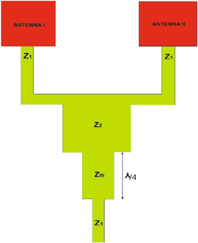
Figure 1. Microstrip Feeding Network.
Download figure:
Standard image High-resolution imageThis design of power dividers and antenna arrays are simulated and upgraded utilizing the CST Microwave Studio Suite.
4. Slotted single SIW ENZ antenna
In order to improve the gain of the antenna, an array is designed using slotted single SIW ENZ antenna [14]. The single element of the proposed antenna with parameters are given in figure 2. The parameter values are optimized to design the antenna using RT Duroid substrate with ε r = 2.2 on 0.8 mm thickness and they are given as w = 9.6 mm, a = 16 mm, L = 40 mm, ws = 0.7 mm, r = 0.5 mm, P = 1.5 mm and wm = 2.47 mm. The antenna operates at 5.01 GHz with return loss value 26.77 dB with a −10 dB bandwidth of 148 MHz is shown in figure 3. The simulated gain of the single element SIW ENZ antenna is 5.01 dB.
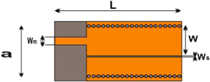
Figure 2. Single SIW ENZ Antenna.
Download figure:
Standard image High-resolution image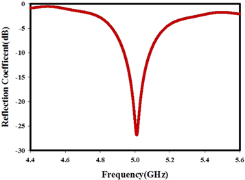
Figure 3. Reflection Characteristics.
Download figure:
Standard image High-resolution imageTwo types of arrays are described in the following sections.
5. 1 × 2 antenna array
The two-element slotted SIW ENZ antenna are connected with 1 × 2 microstrip power divider as the feed network. The schematic of the 1 × 2 SIW ENZ antenna array is shown in figure 4. Here, increasing the element spacing increases the gain and decreases the bandwidth of the antenna.
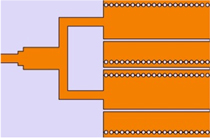
Figure 4. 1 × 2 SIW ENZ Antenna Array
Download figure:
Standard image High-resolution imageThe reflection characteristics of the 1 × 2 SIW ENZ antenna array is shown in figure 5. The array operates at 5.03 GHz with return loss value 38.78 dB with a −10 dB bandwidth of 198 MHz.
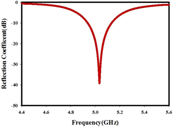
Figure 5. Reflection Characteristics.
Download figure:
Standard image High-resolution imageThe electric field distribution of the 1 × 2 SIW ENZ antenna array is shown in figure 6. The e-field shows a genuinely uniform field over the slot for the antenna array. It infers that the radiation from the slot will be in a similar phase. That is why the proposed antenna exhibit epsilon near-zero property of metamaterials.
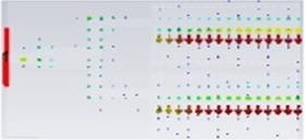
Figure 6. E-field Distribution.
Download figure:
Standard image High-resolution imageThe 3D radiation pattern of the array is shown in figure 7. The radiation is concentrated on the top of the radiating structure. The simulated gain of the proposed 1 × 2 antenna array is 7.676 dB.
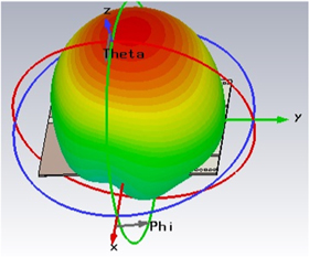
Figure 7. Radiation Pattern.
Download figure:
Standard image High-resolution image6. 1 × 4 antenna array
Two 1 × 2 antenna array is added to form a 1 × 4 SIW ENZ antenna array. 1 × 4 power diver is used for the feeding network. The Schematic of 1 × 4 SIW ENZ antenna array is shown in figure 8.
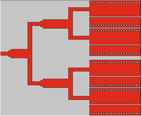
Figure 8. 1 * 4 Antenna Array.
Download figure:
Standard image High-resolution imageThe reflection qualities of the proposed array is shown in figure 9. The array operates at 5.05 GHz with return loss value 36.4 dB. The bandwidth of the 1 × 4 SIW ENZ antenna array is 253 MHz. Here we can see that increasing the number of elements increases the bandwidth of the antenna array.
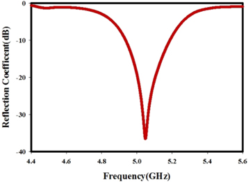
Figure 9. Reflection Characteristics.
Download figure:
Standard image High-resolution imageThe electric field distribution of the antenna is shown in figure 10. The electric field shows uniform filed over the antenna array elements. The 3D Radiation pattern of the antenna array is shown in figure 11 and it is concentrated above the patch array. The simulated gain of the proposed antenna array is 10.55 dB. Increasing the number of elements increases the gain of the antenna.
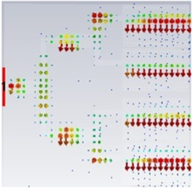
Figure 10. E-field Distribution.
Download figure:
Standard image High-resolution image
Figure 11. Radiation Pattern.
Download figure:
Standard image High-resolution imageTable 2 summarized the gain and bandwidth of different types of antennas.\
Table 2. Gain and Bandwidth.
| Antenna Type | Bandwidth (MHz) | Gain (dB) |
|---|---|---|
| Single Element Antenna | 148 | 5.01 |
| 1 × 2 antenna Array | 198 | 7.68 |
| 1 × 4 Antenna Array | 253 | 10.55 |
7. Experimental results
In the previous sections, we have designed and studied the properties of 1 × 2 and 1 × 4 SIW ENZ antenna array. Bandwidth and gain of the 1 × 4 SIW ENZ antenna array is greater than that of 1 × 2 SIW ENZ antenna array. To demonstrate the design, one prototype of 1 × 4 SIW ENZ antenna array is realized for experimental validation. The proposed antenna is fabricated and its characteristics are analyzed using an HP8510C network analyzer.
The fabricated prototype of the 1 × 4 SIW ENZ antenna array is shown in figure 12. The measured and simulated reflection characteristics of the 1 × 4 SIW ENZ array are shown in figure 13. The antenna operates at 5.06 GHz with a return loss value of 19.18 dB. Measured results show that the bandwidth of the antenna ranging from 4.93 GHz to 5.13 GHz is 190 MHz. From reflection characteristics, it can be seen that simulated and measured results of the antenna array are agreeing with some errors, which can be attributed to the fabrication error.
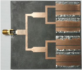
Figure 12. Fabricated Antenna.
Download figure:
Standard image High-resolution image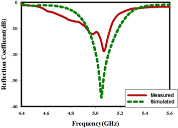
Figure 13. Reflection Characteristics.
Download figure:
Standard image High-resolution imageThe measured gain of the antenna array is shown in figure 14. Which shows a peak gain of 9.07 dB. The measured radiation pattern of the antenna array with E-plane and H-plane is shown in figure 15.
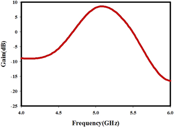
Figure 14. Measured Gain of the Antenna Array.
Download figure:
Standard image High-resolution image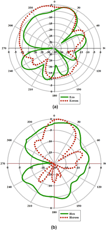
Figure 15. Measured Radiation Pattern (a) E-Plane (b) H-Plane.
Download figure:
Standard image High-resolution image
8. Conclusion
An array of slotted substrate integrated waveguide Epsilon Near Zero antenna is introduced. An effective ENZ material was outlined utilizing the connection between the cut-off frequency in a waveguide and permittivity. In this paper, studies of 1 × 2 and 1 × 4 SIW ENZ antenna arrays are presented. Microstrip power dividers are used as the feeding network for antenna arrays. The proposed antenna can be fabricated using planar technology. The particular advantage of the antenna is to achieve high gain or highly directive radiation designs and higher bandwidth. There has been a great deal of research carried out in the area of microwave systems an antennas working at the future 60 GHz communication bands. These slotted SIW ENZ antenna arrays discovers applications in millimetre wave frequencies, where conventional patch antennas are hard to manufacture.