

Abstract
Small-scale electromagnetic soft actuators are characterized by a fast response and simple control, holding prospects in the field of soft and miniaturized robotics. The use of liquid metal (LM) to replace a rigid conductor inside soft actuators can reduce the rigidity and enhance the actuation performance and robustness. Despite research efforts, challenges persist in the flexible fabrication of LM soft actuators and in the improvement of actuation performance. To address these challenges, we developed a fast and robust electromagnetic soft microplate actuator based on a laser-induced selective adhesion transfer method. Equipped with unprecedentedly thin LM circuit and customized low Young's modulus silicone rubber (1.03 kPa), our actuator exhibits an excellent deformation angle (265.25°) and actuation bending angular velocity (284.66 rad·s−1). Furthermore, multiple actuators have been combined to build an artificial gripper with a wide range of functionalities. Our actuator presents new possibilities for designing small-scale artificial machines and supports advancements in ultrafast soft and miniaturized robotics.
Highlight
Femtosecond lasers provide a highly precise and flexible means of fabrication.
The precise motion of the actuator is the Lorentz force driven for control via current.
The actuator boasts an ultrafast angular velocity and extensive deformation.
The actuators endure 2.4M motion cycles with exceptional robustness.
Artificial grippers consisting of actuators capture diverse objects.
Export citation and abstract BibTeX RIS

Original content from this work may be used under the terms of the Creative Commons Attribution 4.0 license. Any further distribution of this work must maintain attribution to the author(s) and the title of the work, journal citation and DOI.
Corrections were made to this article on 20 March 2024. Supplementary material names were corrected and a punctuation error was corrected.
1. Introduction
Human muscles produce corresponding dexterous movements after receiving signals sent by the brain and transmitted by neurons (figure 1(a)). The emergence of soft robots provides an excellent candidate for mimicking human movements and feedback mechanisms. With the removal of stiff materials, soft robots are more suitable in healthcare, biomedicine, industry, and other fields than traditional rigid robots [1–4]. With the demand for miniaturization of these soft robots, soft actuators (as the fundamental elements of soft robots) also need to be miniaturized [5, 6]. However, the design and fabrication of small-scale soft actuators have become a major challenge. In recent decades, various small-scale soft actuators have been proposed (e.g. shape memory actuators, liquid crystal actuators, and dielectric elastomer actuators) based on different fabrication methods (e.g. 3D printing [7, 8], mold shaping, and continuous spinning [9]), which successfully convert different energy sources (including magnetism [10–16], heat [17–21], electricity [22–26], light [27–30], pH [31–34], and humidity [35–38]) into the kinetic energy of small-scale soft actuators. Among these, electromagnetic soft actuators have received increasing attention due to their fast response, high robustness, and good controllability [39].
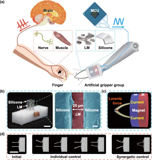
Figure 1. Artificial soft microplate actuator (SMPA) gripper. (a) Similar to human fingers, multiple SMPAs were actuated through the coordination of liquid metal (LM) circuits and ultrasoft silicone rubber to capture/release target objects. (b) The SMPA gripper consisting of two SMPAs. The SEM image on the right depicts a cross section of the LM circuit, with a minimum thickness of only 25 μm. (c) The SMPA gripper was placed in a magnetic field generated by a cylindrical permanent magnet. With applied current, the parts of the LM circuits that were perpendicular to the magnetic lines were driven by the Lorentz force, causing the SMPAs to bend toward each other in the middle. (d) The artificial SMPA gripper can achieve individual or synergetic control of SMPAs through a control system based on microcontroller unit (MCU). Scale bars are 5 mm and 10 μm in (b) and 10 mm in (d).
Download figure:
Standard image High-resolution imageAs early as 2002, Kim et al electroplated copper into conductive circuits on the surface of a polymer film and encapsulated them internally to develop a soft actuator that can be driven by the coordination of the magnetic field and current [10]. However, the inherent rigidity of copper circuits limits the deformability of the actuator. To address this issue, liquid metal (LM), characterized by fluidity and conductivity, has been utilized as a circuit material for small-scale electromagnetic soft actuators [40–43]. The use of LM can reduce rigidity and enhance the robustness of the actuator. For example, Jin et al have developed a stretchable electromagnetic actuator that can be used as a loudspeaker [11]. This electromagnetic actuator contained a microchannel fabricated by photolithography and was injected with LM. Furthermore, Guo et al have developed a completely soft electromagnetic actuator by employing a spray painting method with masks to prepare an LM circuit on a Polydimethylsiloxane (PDMS) film [12]. Nevertheless, this LM circuit-based soft actuator can achieve ∼23° of deformation when operated with low currents (<0.5 A), with a potential for further improvement in bending property. Mao et al have developed a highly robust electromagnetic soft actuator that can withstand relatively higher current by injecting LM into microchannel within the shell made of soft silicone, resulting in breakthroughs in both response speed and deformation range [13]. However, the fabrication processes of LM circuits are complicated, inflexible, and require masks or molds. Subsequently, Mao et al have optimized the fabrication process and developed an electromagnetic soft actuator based on 2D printing [14]. Although the fabrication flexibility has been improved, the thick LM circuit results in the large size of the electromagnetic actuator, which limits actuation performance.
Therefore, there are two challenges in the development of small-scale electromagnetic soft actuators based on LM: (a) inability for quick and flexible fabrication of ultrathin LM circuits (thickness of approximately 50 μm) and (b) poor actuation performance under low driving current (less than 1.0 A).
To address these challenges, we developed an electromagnetic soft microplate actuator (SMPA) composed of LM and customized silicone rubber. The SMPA was fabricated by the laser-induced selective adhesion transfer (LISAT) method, which presents a transfer printing technique for LM patterning. Leveraging the fast fabrication velocity, remarkable precision, and flexibility inherent in femtosecond laser micro/nanomanufacturing technology [44–46], this methodology facilitates the swift and flexible fabrication of ultrathin LM circuits, as reported in our previous work [47]. Combining the LISAT method with customized low Young's modulus silicone rubber (table S1 illustrates a comparison with other commonly used soft materials and silicone rubber materials), our SMPA is superior to traditional small-scale electromagnetic soft actuators in multiple aspects: quicker and more flexible fabrication, larger deformation range, and higher motion speed. In addition, our SMPA exhibited great robustness (remaining stable after working over 2.4 million times). More significantly, we created an artificial gripper by combining multiple SMPAs into an SMPA gripper. By taking advantage of the softness, large deformation range, and high actuation speed of the SMPA, the SMPA gripper excels at capturing and releasing high-speed moving objects, live water striders, and droplets of different sizes and chemical properties. Our SMPA provides a simple, flexible, and general strategy for the design and assembly of various small-scale soft robots.
2. Results and discussion
2.1. Fabrication of electromagnetically responsive SMPA
Similar to the fingers of a human being, we designed and fabricated an SMPA based on electromagnetic response. As shown in figure 1(b), the LM was encapsulated in silicone rubber as a circuit. Galinstan is a nontoxic, highly conductive material that displays low viscosity and liquid behavior at ambient temperature. Galinstan can swiftly form a remarkably thin oxide layer on its surface when exposed to air. This oxide layer can adhere to a smooth silicone surface while exhibiting less adhesion to a rough silicone surface [40–42]. To pattern the LM into the circuit, we employed the LISAT method [47] to accurately and flexibly change the roughness of different areas on the silicone surface. Femtosecond laser micro/nanofabrication allows the precise control of the surface morphology by varying the parameters [48, 49]. Here, we achieved modulation of the surface roughness by simply changing the scanning interval parameter. (See note S1 for the detailed mechanism of femtosecond laser-induced LM adhesion and note S2 for the characterization techniques pertaining to LM adhesion on the sample surface.) We attached a silicone surface with a circuit pattern to the surface of the LM bath. After removing the silicone surface from the surface of the LM bath, LM only adheres to the untreated smooth areas of the silicone surface, while the treated rough areas remain clean. (The fabrication process of SMPA is described in detail in figure S4.) It is worth mentioning that the LM patterns are as thin as ∼25 μm due to our unique transfer printing in the LISAT method. The illustration on the right side of figure 1(b) shows the SEM cross section of the SMPA. In addition, the thickness of LM circuits can be increased by multiple attachments to the LM bath. The thicknesses of the SMPAs used for fast actuation in later sections were all maintained at ∼50 μm to avoid potential damage to the LM circuits during the ultrafast actuation process (figures S6 and S7). With the high-resolution processing and rapid fabrication capabilities of the femtosecond laser, the LISAT method offers a simple and rapid fabrication process, along with the ability to flexibly design and fabricate LM patterns. As shown in figure S8, a variety of predesigned LM patterns were obtained on the silicone surface.
To utilize Lorentz force, the circuit in our SMPA is constructed in a 'U' shape. When the SMPA is placed in a magnetic field and an electric current is applied, the Lorentz force acting on the horizontal part of the LM circuit (which is perpendicular to the magnetic lines) can cause the bending motion of the SMPA (figure 1(c); see note S3 for a detailed calculation regarding the driving force). Furthermore, the motion of the SMPA can be precisely controlled by changing the magnitude, direction, and frequency of the current. In this way, SMPAs can complete synergetic or individual motions (figure 1(d)).
2.2. Geometric dimension design of SMPA
The geometry of our SMPA is primarily characterized by four parameters: thickness (h), width (x), length (y), and width of the LM circuit (w), as illustrated in figure 2(a). The thickness of the silicone film can be precisely controlled by the spin coating speed (figure S9). The width (x), length (y), and width of the LM circuit (w) were determined by the LISAT pattern design. The LM circuit is located 0.8 mm (c) away from the boundary of the silicone basement to prevent LM leakage. An inappropriate thickness (h) may result in collapse or poor bending property. Four SMPAs with different thicknesses were evaluated in an upright position to demonstrate the effect of thickness on the SMPA (figure 2(b)). Specifically, the SMPAs with thicknesses of 289 and 400 μm were too thin and susceptible to collapse, whereas the 885 μm SMPAs were too thick, resulting in poor bending property. Thus, the optimal thickness (h = 528 μm) was chosen for the actuator design, which was obtained at a spin coating speed of 450 rpm. The aspect ratio (x/y) also has an impact on the bending property of the SMPA. To determine the optimal aspect ratio, the bending angles (α) of three SMPAs with different aspect ratios under different currents were measured (figure 2(c)). The SMPAs with a low aspect ratio of 1:3 exhibit excellent bending property; yet, their tall height renders them susceptible to collapse. Conversely, the SMPAs with a high x/y ratio of 1:1 exhibited poor bending property. Therefore, the x/y of 1:2 was chosen as the optimal value. Furthermore, the thickness (h) and aspect ratio (x/y) have synergistic effects on the vertical standing and bending properties of the SMPAs. As illustrated in figure 2(d), the green dots represent the SMPAs that can stand upright and exhibit good bending property, whereas red crosses indicate that the SMPAs cannot stand upright, and pink crosses indicate poor bending property. (Table S2 shows more details on the vertical standing and bending properties of the SMPAs with different aspect ratios and thicknesses.)

Figure 2. Dimensional design and bending properties of the SMPAs. (a) The dimensions of the SMPAs were defined by four geometric parameters: thickness (h), aspect ratio (x/y), width of the SMPA (x), and width of the LM circuit (w). (b) Vertical standing of the SMPAs with varying thicknesses (aspect ratio x/y = 1:2 and width x = 4 mm). (c) Bending angles (α) achieved by the SMPAs with varying aspect ratios (x/y) in response to increasing current. The thickness (h) and width of the SMPAs (x) were 528 μm and 4 mm, respectively, whereas the width of the LM circuit (w) was 0.8 mm. (d) Phase diagram revealing the vertical standing and bending properties with different geometric parameters. The green dots represent the SMPAs that can stand upright and exhibit good bending property, the red crosses indicate the SMPAs that cannot stand upright, and the pink crosses indicate poor bending property (see table S2 for details). (e) Bending angles (α) achieved by the SMPAs with varying widths (x) in response to increasing current. The thickness (h) and aspect ratio (x/y) of the SMPAs were 528 μm and 1:2, respectively, whereas the width of the LM circuit (w) was 0.8 mm. (f) Bending angles (α) achieved by the SMPAs with varying widths of the LM circuit (w) in response to increasing current. The thickness (h), aspect ratio (x/y), and width of the SMPAs (x) were 528 μm, 1:2, and 4 mm, respectively. Scale bars are 10 mm in (b) and 5 mm in (c). Error bars denote the standard deviation of the measurements.
Download figure:
Standard image High-resolution imageThe width of the SMPA (x) also influenced its bending property. As shown in figure 2(e), a series of SMPAs with different widths (3.0, 3.5, 4.0, and 4.5 mm) was measured with increasing current in a magnetic field to characterize their bending properties. (The thickness and aspect ratio remained unchanged at 528 μm and 1:2, respectively). It is noteworthy that the SMPAs with a width of 4.0 mm achieved a maximum bending angle (α) of up to 90° under a current of 0.55 A, which was unattainable by the SMPAs with the other widths. This is because a narrower width results in a weaker Lorentz force acting on the horizontal part of the LM circuit of the SMPA, whereas a wider width increases the length of the SMPA but causes the horizontal circuit to be farther away from the magnet, resulting in a reduction in the driving Lorentz force. The LM circuit width (w) had little effect on the bending properties of the SMPAs (figure 2(f)). However, if w is too wide (e.g. w = 1 mm), the circuit is too close to the boundary of the silicone basement, resulting in LM leakage. Conversely, if w is too narrow (e.g. w = 0.6 and 0.4 mm), it may be susceptible to open-circuit failure during the motion of the SMPA. Based on the experimental results, the optimized dimensions of the SMPAs were obtained (h = 528 μm, x/y = 1:2, x = 4 mm, and w = 0.8 mm).
The presence of electrical resistance inevitably resulted in heat generation, as the SMPAs were continuously energized. To characterize the thermal behavior of the SMPAs, we conducted a series of electrified heating experiments (see note S4). When a current of 1.0 A was applied, the maximum temperature of the SMPAs did not exceed 50 °C, a value that was significantly below the viscous flow temperature (the temperature of transition into the viscous flow state) of silicone rubber [50].
2.3. Mechanism of electromagnetically responsive SMPA
Note S3 shows the analysis and calculation of the Lorentz force on SMPA when energized in a magnetic field, from which it is known that only the Lorentz force generated by the horizontal part of the LM circuit acts as the driving force. Moreover, based on the Lorentz force rule, the direction of the driving force should be perpendicular to the plane containing both current and magnetic lines. Therefore, we conducted a force analysis of the SMPA in a two-dimensional plane (figure 3(a)). To fix the SMPA in place, the end of the SMPA was placed on a 3D-printed brace. To precisely regulate the magnitude, direction, and switching frequency of current, we employed a control system (figure S12) consisting of a microcontroller unit (Arduino) and relays to output current signals. The Lorentz force, indicated by the yellow arrows in figure 3(a), was generated when current was applied. The SMPA can bend in two directions, according to the directions of current. The bending angle was precisely regulated and controlled by current (movie S1, supporting information). For instance, the SMPA reached a 90° bend when a current of 0.55 A was applied, which corresponds to the simulation results (figure 3(b)).
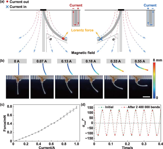
Figure 3. Characterization and simulation of the electromagnetically responsive bending properties of the SMPAs. (a) Free-body diagram of SMPA in 2D plane. Only the Lorentz force acting on the part of the LM circuit perpendicular to the magnetic lines drove the SMPA to bend. The bending direction of the SMPAs was determined by the direction of current. (b) Bending of the SMPAs under different magnitudes of current. The upper images show the simulation results, whereas the lower images show the actual test results. (c) Correlation between the force generated by the SMPAs during bending and the magnitude of current. (d) Fatigue testing was performed on the SMPAs at a current of 0.6 A at 20 Hz. Comparison of the correlation between the bending angle and time at the beginning of the test and after 17 h. The result demonstrates that within the durations of 0.4 s during the initial and final stages, the bending angle of the SMPAs remained essentially unchanged, attesting to their high durability (see note S5 and figure S13 for details). Scale bar is 5 mm (b). Error bars denote the standard deviation of the measurements.
Download figure:
Standard image High-resolution imageIn addition to investigating the bending motion of the SMPAs, the generated force was also examined. For this purpose, the SMPAs were placed against a dynamometer. As current increased, the SMPA bent gradually and applied a greater force to the dynamometer (figure 3(c)). At a current of 1.0 A, the force generated by the SMPA can reach ∼0.76 mN. In addition, the robustness of our SMPA was measured using long-term fatigue tests (see note S5). Specifically, the SMPA was subjected to a square-wave electrical current of 0.6 A at 20 Hz for a continuous 17 h period. During this period, bending motions were repeated over 2.4 million times. The maximum bending angle was ∼120°. Remarkably, even after prolonged utilization, the bending property of the SMPA remained virtually unchanged compared with its initial state (as shown in figure 3(d) and movie S2, supporting information), demonstrating the exceptional robustness of the SMPA.
2.4. Ultrafast and wide-range motion properties of the SMPA
Apart from the bending property of the SMPA under a constant current, we also conducted a property analysis under dynamic current. Dynamic property analysis was conducted by inputting the current in the form of a square wave. The SMPA rapidly switched in different bending directions at varying frequencies. The square-wave current frequency increased gradually from 2.5 to 50 Hz (in 2.5 Hz intervals). We applied currents of 0.4, 0.6, 0.8, and 1.0 A to measure the maximum deformation angle (θmax) of the SMPA at different switching frequencies (figure 4(a)) and calculate the corresponding maximum bending angular velocity (ωmax; figure 4(b) demonstrated the correlation between ωmax and actuation frequency, see note S6 for a detailed calculation). Movie S3, supporting information, shows the real-time motions of the SMPAs. When a square-wave current of 1.0 A at 20 Hz was applied to the SMPAs, they exhibited a maximum deformation angle of (265.25 ± 5.01) ° and a maximum bending angular velocity of (284.66 ± 7.89) rad·s−1. A single deformation of bending and recovering was identified as one complete motion. Because every square-wave period contains both positive and negative peaks, the SMPA completed two motions within each period. Figure 4(c) depicts the instantaneously intercepted images of the two motions of the SMPA within one square-wave period (1.0 A at 20 Hz square-wave current), with each motion taking only 25 ms.
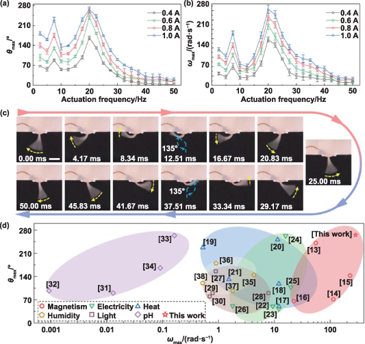
Figure 4. Ultrafast bending motions of the SMPAs and their application in the SMPA gripper (composed of two parallel SMPAs). (a) Correlation between the maximum deformation angle (θmax) of the SMPAs and the frequency of the square-wave current with varying applied currents. (b) Correlation between the bending angular velocity (ωmax) of the SMPAs and the frequency of the square-wave current with varying applied currents (see note S6 for a detailed calculation). (c) Real-time images of the two bending motions within one square-wave period (when a current of 1 A at 20 Hz was applied). Each motion required 25 ms, with a snapshot interval of approximately 4.17 ms. (d) Benchmarking of responsive bending actuators. The key metrics for comparing the properties of responsive bending actuators are the maximum deformation angle (θmax) and maximum bending angular velocity (ωmax). In this study, electromagnetically responsive SMPAs were compared with several other stimulus-responsive bending actuators. The red star represents our work, the red circles represent magnetism, the blue triangles represent heat, the green inverted triangles represent electricity, the brown squares represent light, the purple diamonds represent pH, and the golden pentagons represent humidity. The SMPAs in this study were classified as 'magnetism' (red star). Scale bars are 5 mm (c). Error bars denote the standard deviation of the measurements.
Download figure:
Standard image High-resolution imageBecause the SMPA was actuated through bending deformation, the maximum deformation angle (θmax) and maximum angular velocity (ωmax) were considered as crucial metrics for evaluating its properties. Based on these two metrics, our SMPA was compared with previously reported small-scale soft actuators driven by magnetism, heat, electricity, light, humidity, and pH stimuli (figure 4(d), table S3). In comparison, the angular velocity ωmax of our SMPA was ∼25.5% higher than that of the best reported study [15], and the maximum deformation angle θmax was consistent with that of the best reported study [24]. These significant improvements can be attributed to a confluence of factors: (a) the softness of the customized low Young's modulus silicone rubber material (1.03 kPa); (b) unlike other rigid conductor materials, the liquid behavior of LM imparts complete softness to the SMPA; and (c) the LM circuit is fabricated through the transfer printing method, resulting in an ultrathin thickness that enables the actuator to be much thinner.
2.5. Capture and release of different targets by the SMPA gripper
To extend the functionality of our SMPA, we created an SMPA gripper by combining multiple SMPAs that can act as an artificial gripper to capture and release target objects. The count and arrangement of SMPAs in the SMPA gripper were ascertained to conform to the shape of the target object (figure S14). A cylindrical permanent magnet was secured to a stage that can move horizontally and vertically to ensure the SMPA gripper's transfer function of the target objects (figure S15). In this section, we demonstrate the versatility of the SMPA gripper with real-world examples of handling fast-moving solid targets and a wide range of liquid targets.
Because of the wide-range and ultrafast motion capabilities of the SMPA, the SMPA gripper can successfully capture fast-moving targets with a speed of ∼1 m·s−1 (figure 5(a) and movie S4, supporting information). In addition, the SMPA gripper can transfer delicate targets safely owing to its ultrasoft feature. In figure 5(b) and movie S5, supporting information, a water strider (a well-known insect for its ability to rapidly move on water surface) was captured by the SMPA gripper. The SMPA gripper raised the insect and transferred it to another culture dish. After being released, the water strider continued to move on the water surface. These two rapid capture experiments demonstrated the high performance and softness of our SMPA gripper.

Figure 5. SMPA gripper captured liquid droplets. (a) Screenshots of the SMPA gripper capturing a rapidly moving object (with a flight speed of ∼1 m·s−1 with each snapshot taken at intervals of 16.7 ms). (b) The SMPA gripper captured a water strider and transferred it to another Petri dish for release. (c) The SMPA gripper composed of three SMPAs. The illustration located at the bottom-right corner depicts the surface micro/nanostructure of the SMPA surface after femtosecond laser scanning to realize superhydrophobicity (water contact angle: (158.2 ± 0.8) °). (d) The SMPA gripper can capture liquid droplets with minimum and maximum volumes of 0.5 and 40 μl, respectively. (e) The SMPA gripper picked up a droplet of NaOH and transported it to a designated location, where it reacted with CuSO4 to form Cu(OH)2. (f) The SMPA gripper picked up a droplet of HCl and transported it to a designated location, where it reacted with AgNO3 to form AgCl. Scale bars are 20 μm in (a) and 5 mm in (b)–(f).
Download figure:
Standard image High-resolution image
In addition to solid targets, the SMPA gripper also has the capability to capture and transfer a wide range of liquid targets. To achieve a more stable droplet capture application, the SMPAs in the SMPA gripper were arranged in equilateral triangles, as shown in figure 5(c). The outer silicone surfaces of the SMPAs were treated with a femtosecond laser to induce micro/nanostructures, which ensured the superhydrophobicity of the SMPA surface. The small heat-affected zone of femtosecond laser micro/nanoprocessing protects the LM circuit inside the SMPA from damage. To investigate the range of droplet volumes that the SMPA gripper can capture, deionized water (DIW) droplets with different volumes were used as the capturing objects. Figure 5(d) and movie S6, supporting information, exhibit video recordings and optical images of the capture process for droplets of varying volumes. The results demonstrate that the SMPA gripper has the ability to capture droplets with a wide volume range from 0.5 to 40 μl.
In addition to capturing ordinary droplets, such as DIW, the SMPA gripper is also resistant to chemical corrosion and can handle droplets with alkalinity and acidity. The experiments illustrated in movies S7 and S8, supporting information, involved capturing and transferring droplets of NaOH (1 mol·l−1; 20 μl) and HCl (0.23 mol·l−1; 20 μl) solutions, respectively (figures 5(e) and (f)). To visualize the alkalinity and acidity of the target droplets, the droplets of CuSO4 (0.5 mol·l−1; 20 μl) and AgNO3 (0.05 mol·l−1; 20 μl) solutions were intentionally prepared on the opposite side. The SMPA gripper successfully captured and transferred the droplets to the desired location. Upon releasing the NaOH and HCl droplets and mixing them with CuSO4 and AgNO3 droplets, respectively, rapid reactions occurred. These reactions produced deepening blue precipitates of Cu(OH)2 and white precipitates of AgCl, respectively. These experiments demonstrated the capture and transfer of corrosive target droplets by the SMPA gripper, benefiting from the corrosion-resistant silicone rubber.
3. Conclusion
In this study, we employed direct femtosecond laser ablation to induce micro/nanostructures on customized silicone rubber with a low Young's modulus and achieved selective transfer of LM to prepare an ultrathin soft circuit. By utilizing encapsulation processes, we developed a highly robust ultrafast electromagnetic SMPA. Notably, our SMPA exhibited precise control over current magnitude, direction, and switching frequency, which enabled versatile regulation within an immutable magnetic field. Compared with previously reported electromagnetic soft actuators, our SMPA exhibited enhancements in both the deformation angle and response bending angular velocity. Furthermore, multiple SMPAs can be combined to form a fast-responsive SMPA gripper capable of rapidly capturing/releasing target objects. The soft body of SMPAs, coupled with a low driving current (less than 1.0 A), ensures the preservation of biological samples without causing harm and reduces safety concerns. Moreover, through the implementation of femtosecond laser-induced superhydrophobicity of the SMPA surface, the SMPA gripper acquires the ability to capture liquid targets with diverse chemical properties. In contrast to traditional grippers, our SMPA gripper offers ease of miniaturization owing to its simple structure, flexible fabrication process, and low driving current requirements. Further miniaturization of the size and collaboration with more SMPAs hold promise for advancing the development of future-generation soft micro-robots endowed with exceptional capabilities. These advancements offer extensive application prospects in the fields of flexible manufacturing, targeted drug delivery, and noninvasive surgery.
4. Methods
Materials of the SMPA: the SMPAs consist of two layers of silicone film (with one layer acting as the basement and the other layer acting as the encapsulation), an LM circuit, and copper foil electrodes. The silicone film, which served as the main body, was an addition-cured silicone product customized by Dongguan Borui Trading Co., Ltd. The LM used in this study was a gallium-based liquid alloy with a main composition of 68.5 wt% Ga, 21.5 wt% In, and 10 wt% Sn, which was purchased from Shenyang Jiabei Commerce Ltd. The copper foil patches with a thickness of ∼30 μm that acted as electrodes were purchased from Shenzhen Darit Tape. Water-soluble adhesive tape used to cover the samples during femtosecond laser processing (see figure S16 for details of the covering function of water-soluble tape) was purchased from Aquasol Corporation in the United States with a product code of ASWT-1 and thickness of ∼70 μm.
Femtosecond laser fabrication: the femtosecond laser source employed in this study was a Solstice Ace model produced by Spectra-Physics, USA (80L8TICE-ACE-100F-1K). To perform ablation, a laser beam with parameters of 100 fs, 1 kHz, and 800 nm was used, which was focused by an F-theta lens with a focal length of 100 mm. The laser focus was guided using a galvanometer scanner (model: s-9210d) purchased from Sunny Technology, China. The processing parameters were set at a laser power of 500 mW and scanning speed of 20 mm·s−1 with a scanning interval of 50 μm (see Note S1 for the rationale behind utilizing these laser parameters). The laser spot was scanned along the predetermined path for five cycles, with the first four cycles used to remove the water-soluble tape and the last cycle used to induce rough micro/nanostructures on the surface of the silicone film basement.
Liquid metal transfer: the LM was poured into a culture dish to spread at the bottom. The laser-patterned silicone film was attached to the LM surface, ensuring full contact between the smooth area and the LM surface oxide layer. Afterward, the silicone film was removed, carrying with it the LM that had adhered to the smooth region. If necessary, multiple attachments of the silicone film and LM bath were applied to increase the thickness of the LM pattern.
Expansion of circuit: to integrate the LM circuit with other circuits and power sources, copper foil patches were attached to the silicone film to serve as transitional electrodes with the LM circuit. Because of the poor adhesion of the LM surface oxide layer on copper, the copper foil patches were subjected to electroplating to enhance the adhesive capability of LM (figure S17). Specifically, LM was added to a dish, and then NaOH solution was added to submerge the LM. A copper foil patch was caught by the negative terminal of a DC power source, and the patch was then inserted into the LM, whereas the positive terminal was only immersed in the NaOH solution. An electroplating layer was formed on the surface of the copper foil patch. The patch with the electroplated layer was then affixed to the LM circuit pattern.
Encapsulation process: the preparation process for encapsulation was the same as that of the silicone basement. The uncured silica gel mixture, which was mixed and degassed, was uniformly poured onto a silicone basement with an LM circuit pattern and copper foil patches. Subsequently, the silica gel mixture was spread by spin coating, and the thickness was controlled by adjusting the rotation speed. (The spin-coating thickness is also shown in figure S9.) Finally, the sample was heated in an oven at 50 °C for 30 min for curing.
Characterization of customized silicone rubber: the Young's modulus of the customized silicone rubber was obtained by tensile and fatigue tests, with a strain rate of 0.5 mm·s−1, following the guidelines presented in the National Standard of the People's Republic of China GB/T1040.3-2006 (type 2), with the specimen geometry specified accordingly. Using a fatigue testing machine (E3000K8953, Instron, UK), the Young's modulus was measured to be 1.03 kPa (figure S18).
Characterization of the magnet: the magnetic field was provided using a cylindrical permanent magnet. The SMPA/SMPA gripper was fixed on the surface of the S pole of the permanent magnet during actuation. To precisely measure the magnetic field at the two poles of the magnet, a gauss meter was employed to measure the field strength at the surface of the magnet, with a value of ∼660 mT. To further characterize the magnetic field provided by the permanent magnet, a simulation of the magnet's magnetic field was performed (figure S19).
Control and power systems: the external circuit comprised an Arduino UNO R3 as a control terminal connected to a computer for input commands, two relays serving as switches for reversing the current flow, and a DC power supply capable of delivering up to 30 V and 10 A. The components were connected, as illustrated in figure S12, and the computer was used to input commands to control the different relays, enabling the transmission of positive or negative current to bend the SMPA in various directions. Additionally, frequency values can be directly input into the computer to adjust the relay switching frequency, thus controlling the vibration frequency of the SMPA.
Characterization of corrosive droplets: the molar concentration of NaOH droplets used for transfer was 1 mol·l−1. HCl droplets were obtained by diluting a 35% hydrochloric acid solution by a factor of 50, resulting in a molar concentration of 0.23 mol·l−1. CuSO4 droplet was prepared by dissolving the solutes in DIW, with molar concentrations of 0.5 mol·l−1, whereas AgNO3 is a solution with a molar mass concentration of 0.05 mol·l−1. The aforementioned materials were all procured from Casmart and produced by Sinopharm Chemical Reagent Co., Ltd.
Acknowledgments
This work was supported by the National Natural Science Foundation of China (Nos. 52122511, 61927814, and U20A20290), Anhui Provincial Natural Science Foundation (2308085QF218), China National Postdoctoral Program for Innovative Talents (BX20230351), China Postdoctoral Science Foundation (2023M733382), National Key R&D Program of China (2021YFF0502700), Major Scientific and Technological Projects in Anhui Province (202203a05020014), Fundamental Research Funds for the Central Universities (WK5290000003 and WK2090000058), and Youth Innovation Promotion Association CAS (Y2021118).
Author contributions
Y C and H W contributed equally to this study. Y C, H W, G L, D W, and Y H conceived the idea and designed the project. Y C, Z C, Y T, X Z, and Q Z performed all experiments. Y C, H W, R L, S J, and S Z performed the characterization. Y C and H W performed the simulation. Y C, H W, and Y H completed the data analysis and figure depiction. Y C, H W, and Y H wrote and revised the paper. J L, G L, D W, J C, and Y H supervised the project.
Conflict of interest
The authors declare that they have no conflicts of interest.