

Abstract
Peripheral magnetic stimulation is a promising assistive technique for rehabilitation. Today's magnetic stimulation devices, designed for transcranial stimulation, operate at currents of 6 kA and higher. This makes them expensive and bulky. Many motor neurons in peripheral nerves are more accessible, have large diameters, and require significantly lower field strengths for stimulation. In this work, we present a simulation environment to determine the threshold current required to trigger an action potential in phrenic nerve motor neurons for different coil geometries. An anatomical model was used for coil placement and realistic field calculations. The field distribution was calculated using the finite integration technique and then applied to a neuronal model to simulate the axon membrane dynamics. For general applicability, the coil-nerve distance and the axon diameter were varied. We show that the required current was approximately 1.3 kA for a nerve-coil distance of 35 mm, which corresponds to 20% of the available power of a commercial TMS device. By including the nearby vagus nerve in the simulations, we showed that accidental stimulation of this nerve is highly unlikely. Our results pave the way for the development of smaller, less complex, and more affordable stimulators and promise to increase the use of peripheral magnetic stimulators in clinical settings.
Export citation and abstract BibTeX RIS

Original content from this work may be used under the terms of the Creative Commons Attribution 4.0 licence. Any further distribution of this work must maintain attribution to the author(s) and the title of the work, journal citation and DOI.
1. Introduction
Since the invention of the transcranial magnetic stimulator in 1985 by Barker and colleagues [1], magnetic nerve stimulation has received increasing attention in research and clinical practice. Compared to direct electrical stimulation with surface electrodes, it reaches deeper nerves and provides a painless and more precise method of non-invasive nerve stimulation.
Magnetic stimulation is predominantly associated with transcranial magnetic stimulation (TMS). It is used in clinical neurophysiology, e.g., in rehabilitation [2] and in psychophysiology, like the treatment of depression [3–6]. In contrast, peripheral magnetic stimulation (PMS) is largely unexplored although it offers a variety of advantages. Some studies have demonstrated the feasibility of artificial ventilation by phrenic nerve (PN) stimulation [7–11]. Other potential applications have been reported in sensorimotor issues such as neuromuscular rehabilitation after stroke or spasticity [12–18]. Because it is non-invasive, painless, and has considerable penetration depth, magnetic stimulation offers attractive advantages over surface electrodes or implants. However, PMS is not yet established as a treatment modality. This may be due to the size and complexity of the devices, but also to the high energy consumption of magnetic stimulation systems, which makes it difficult to compete with electrical stimulation. Nonetheless, the amount of energy strongly depends on the thickness of the target axon [19–21]. Motor neurons in the peripheral system are thicker than axons in the central nervous system (CNS) and can be stimulated with significantly less energy than thinner axons [22, 23]. Hence, a magnetic stimulator for peripheral nerves could be smaller, less complex, and much cheaper than a TMS device. For some applications, such as ulnar nerve stimulation at the elbow, experiments on human subjects are efficient and easy to perform. Other stimulation targets, such as the phrenic nerve, are more complex and experiments are difficult or even dangerous. To analyze such applications, the development of reliable simulation frameworks can provide more insight. For the analysis of specific stimulation parameters such as coil geometry or position, current shape, and field distribution, simulations have already provided valuable results [24–30]. Accurate predictions of the threshold coil current or voltage in the pulse capacitor require two simulation steps. First, the electric field distribution must be calculated with respect to the tissue. Second, a neuronal model should be used to understand the nerve's response to the electric field distribution. Neuronal models combined with anatomical finite element models for TMS are well described in the literature [31–34]. For peripheral stimulation, Kosta et al investigated an anatomical model of the rat together with a neuronal model [25]. Davids et al calculated a field distribution in an anatomical model and developed a tool to predict stimulation using the activation function [26]. Pisa et al determined thresholds for stimulation of the median nerve in the forearm using a finite difference model in combination with a neuronal model [35]. The latter work presented a simulation environment that includes all the contributing mechanisms and provides the required capacitor voltage. Due to the individual characteristics of the human body, predictions for parameter variations are necessary. In this work, we demonstrate a comprehensive simulation environment for the example of the phrenic nerve in the neck of a model from the Visible Human Project [36]. It includes parametric descriptions for axon diameter and coil nerve distance, which are the main variables that influence stimulation thresholds. Similar to the above-mentioned research, the simulation is divided into two major parts. First, the electric field distribution of the stimulation coil is evaluated. Secondly, the field distribution in an anatomical model is applied to a neuronal model to determine threshold currents. Both, the field in the anatomical model and the neuron model take into account parameter ranges to cover individual variations.
2. Methods
2.1. Anatomical model
The heterogeneous (28 layers of tissue) biological model "Nelly" (59-year-old female, 162 cm, 86 kg) used in this paper is based on the Visible Human Project of the National Library of Medicine [36]. Inside the model we positioned the phrenic nerve and the vagus nerve, using anatomical illustrations as a guide [37]. The nerve position is exemplary and was varied during the experiments because the exact path of the nerve and its distance from the body surface varies from person to person. The dispersion relation of biological materials was modeled by the Cole-Cole equation [38]. It was used to interpolate measured values of permittivity and conductivity of frequency-dependent biological materials. The electromagnetic properties of the biological materials are based on the work of Camelia Gabriel [39], adapted to the relevant stimulation frequency of 5 kHz (electric conductivity σ in  : skin 2 · 10−4; nerve 3.5 · 10−2; fat 2.5 · 10−2; muscle 3.5 · 10−1; bone 2 · 10−2).
2.2. Coil properties
In recent years, several studies have investigated the influence of coil geometry on the resulting electric field, showing that the figure-of-eight (Fo8) coil provides a good compromise between penetration depth and focality [24, 40–45]. In contrast to TMS, the focality of the coil plays a subordinate role in PN stimulation. Therefore, we have designed and used both, an idealized Fo8 coil (figure 1) and an idealized round coil (RC) with lower focality. Both forms can be advantageous depending on the exact positioning. The assigned material is annealed copper litz wire with an electric conductivity of  . The use of stranded wire counteracts increasing resistance due to skin or proximity effect. Stimulation depth is determined by the coil geometry [45] and the current flow through the coil. Since adjusting the current is comparatively easier, we have chosen coil dimensions that can be found in commercially available products. For the Fo8, two single coils with 9 turns and opposite current directions were arranged at a distance of 12 mm from each other. Each coil had an outer radius of 44.5 mm and an inner radius of 13.5 mm with 3 mm wire width and a winding distance of 0.5 mm, as shown in figure 1. For the RC experiments, we used only one of the two single coils. Moreover, we conducted simulations in which we reduced the coil diameters of both coils by 50%. This naturally decreased the generated electric field strength. However, the reduction allowed us to position the coil more flexibly and thus closer to the nerve, which partially compensated for the reduced field strength. In human experiments, smaller coils would have the advantage of being easier to handle and having lower ohmic losses.
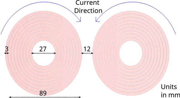
Figure 1. Dimensions and current direction of an idealized Fo8 coil used in the field simulations. The assigned material is annealed copper litz wire with an electric conductivity of  .
.
Download figure:
Standard image High-resolution image2.3. Coil positioning
When determining possible stimulation sites, the accessibility and distance from the stimulation coil to the target nerve must be considered first, as the strength of the electric field decreases rapidly with distance from the coil [46]. If we look at the course of the phrenic nerve from its origins in the cervical spine to its branches at the diaphragm, it is clear that the shortest distance to the outer skin is at the level of the neck [47]. Therefore, the initial position of the coil was set directly on the side of the neck, with the coil being rotated by 20 degrees around its transverse axis (figure 2). The rotation was used to roughly align the coil center with the closest position of the phrenic nerve. The exact final coil position was determined experimentally, taking into account anatomical constraints.
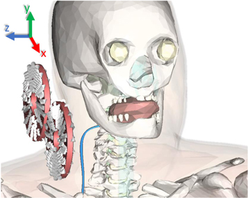
Figure 2. Coil orientation relative to the anatomical model. The phrenic nerve (blue) is shown thicker than in the simulations for better visibility.
Download figure:
Standard image High-resolution imageThe aim was to position the coil optimally in relation to the nerve within the constraints of the model. To achieve this, we examined the three spatial directions (x, y, and z) in which we could move the coil. The y-direction is constrained by the shoulder and the lateral z-direction by the neck of the model. In these directions, the coil can only move farther away from the nerve, which inevitably leads to poorer stimulation conditions. In the antero-posterior x-direction (Δ x = ± 100 mm) the field distributions were determined in 10 mm steps until the best excitation of an exemplary phrenic axon (thickness: 15 μm) was achieved. The simulation process is described in detail in the section Simulation process. At the optimal x-position, the default z-distance between the coil center and the nerve was determined to be zregular = 60 mm for the regular coil and zsmall = 33 mm for the small coil. The large distances are due to the rigid anatomical model, which prevented closer placement of the coil.
The lateral distance can be significantly reduced in real subjects by simply tilting the head or pressing against soft tissue, so we investigated a variation of the lateral distance by repositioning the phrenic nerve in the z-direction. Neck circumference in studies of Latin American and Indian populations showed a standard deviation of approximately 40 mm [48, 49]. Based on these studies, we determined the average distance of the phrenic nerve to the outer skin layer at the level of the C4 vertebra to be 28 mm. To represent as large a population as possible, we varied the lateral distance by Δz = ± 25 mm.
2.4. Electric field calculation
Stimulation of axons is largely determined by the spatial gradient of the electric field [26, 50]. The calculation of the electric field is therefore a crucial step in this simulation. The magnetic field  induced by coils is described by the Biot-Savart law. Faraday's law of induction then defines the curl of the electric field as the time-dependent change of
  . For numerical approximations, the magnetic vector potential
  is usually formulated to decouple the electric field. Similar to
  ,
,  can be derived from charge distributions:
where μ0 is the vacuum permeability and J is the current density. While  is related by the curl operator (
 ), the electric field
  is determined by the time derivative:
To obtain the field in tissue, the electromagnetic properties of the material in the anatomical model are taken into account. The resulting  field distribution is perpendicular to the magnetic field of the coil and is related to the eddy currents in the tissue. Because of the complexity of the given problem, numerical solvers are employed. A popular tool is "CST Studio Suite" (Dassault Systèmes Simulia), which offers a range of solvers. For this application, we used a low-frequency solver in the frequency domain for simulating the time-harmonic behavior in the quasistatic near-field approximation of the Maxwell equations [32, 51]. The finite integration technique is used to solve the equations described above. Mesh properties strongly influence the accuracy of the results. A very fine mesh incorporates a large number of mesh cells which extends the need for memory and simulation time. We used a hexahedral mesh with a numerical matrix inversion accuracy of 1 · 10−3 (a.u.).
The boundary box had a size of 600 mm in each direction and the background material was defined as air (εr = 1.00059, μr = 1.0000004). We used open boundary conditions, assuming that the field at the borders of the boundary box was small. For peripheral stimulation applications, usually, repetitive stimulation at a frequency of about 25 Hz is required [9]. To achieve such high repetition rates, biphasic pulses are usually utilized. Commercially available devices capable of biphasic pulses use pulse lengths between 180 to 370 μs [52]. Therefore, we set our calculation frequency to 5 kHz in a sinusoidal waveform, which corresponds to a pulse duration of 200 μs.
2.5. Neuronal model
To model neuronal activity in the phrenic nerve and the vagus nerve, models of both, myelinated and non-myelinated axons are required. The RMG model [20] is an established approach for human myelinated peripheral axons [25, 26, 51]. We used a single cable model with nodes and linear inter-nodal compartments, which is suitable to determine stimulation thresholds [20, 25, 28]. While the length of the nodes of Ranvier remained always the same (1 μm), the length of the myelin sheaths changed depending on the diameter of the axon. We calculated their length lmyelin based on the RMG model using the equations

where dRanvier is the node of Ranvier diameter, d is the diameter of the myelinated axon, and d0 its reference value of 1 μm [20]. The unmyelinated axons consisted only of nodes of Ranvier. Model parameters for both, myelinated and non-myelinated axons were taken from the RMG model [25, 53]. The model was created using the NEURON environment [54].
According to the Lloyd-Hunt classification, nerve conduction velocity depends linearly on the diameter of the axons [55]. Using the conduction velocities measured in peripheral motor neurons by Ni et al [56], we determined the axon diameters of alpha (15.29 μm) and gamma (9.33 μm) neurons for our experiments. To include as many motor neurons in the nerve as possible, diameters between 9 μm and 19 μm were simulated at 2 μm intervals.
2.6. Simulation process
The first step was to calculate a three-dimensional electric field distribution using CST. The next step was to export the field data of a given volume box (190 mm × 300 mm × 150 mm) including the span of the phrenic nerve. The data contained the spatial distribution of the E-field. The spatial course (x, y, and z coordinates) of the target nerve within the volume box was also exported. Based on the exported spatial course, the nerve was reconstructed from a variable number of myelin sheaths and nodes of Ranvier using a Python script. To average field discontinuities at single nodes, the nodes were shifted along the direction of the nerve by 1.7 mm in 0.1 mm steps. The 1.7 mm corresponded to the longest unit of myelin sheath and node of Ranvier for the axon diameters we used. This procedure resulted in 18 threshold values for each diameter at each distance. The excitation threshold slightly changed when the nodes of Ranvier were shifted, which is indicated by the gray shaded area in figures 3, 4, and 5 (assuming a normal distribution of thresholds). Since only the E-field components running parallel to the nerve are relevant for triggering an action potential [57], the field strength for each section along the axon was calculated based on the direction of the nerve. The potential of each axon segment was then calculated by integrating the E-field along the axon, thus obtaining quasi-potentials [28, 31, 58]. The spatial potential distribution was combined with a temporal field shape, which corresponded to the 200 μs pulse. For the simulation, we used a sinusoidal temporal field shape at the axon. The time-dependent trans-membrane potential relevant to the stimulation of a nerve is described by the cable equations for external electric fields [59]. We used NEURON's extracellular mechanism to solve the cable equation. We defined an action potential as being triggered when it propagated from the activated section to both ends of the axon and depolarized the membrane potential at these sites to ≥15 mV.
3. Results
Using the simulation framework described above, we investigated the threshold currents through a specific coil required for axon activation in the phrenic nerve and the vagus nerve. These threshold currents depend on a number of parameters.
3.1. Parameters for the phrenic nerve
We considered two interdependent parameters for the simulation. Axon diameter describes the thickness of the axons, which plays a crucial role in the ability to stimulate the nerves.
Lateral distance describes the distance between the axon and the coil in the z-direction, referring to the closest point of the axon to the center of the coil.
Figure 3(A) shows the threshold currents through a Fo8 coil as a function of the axon diameter and the lateral distance between the coil and the axon. As expected, the smallest threshold currents resulted for small lateral distances. In addition, the threshold current decreased with increasing axon diameter. We have found that for the default distance of zregular = 60 mm a threshold current between 3 kA and 5 kA was required to trigger an action potential in motor neurons. Looking at the threshold currents for closer lateral distances, one can see the significant effect of this parameter. At z = 35 mm, currents between 1.4 kA and 2.4 kA were sufficient. Figure 3(B) shows the threshold current over the entire z-offset ( ±25 mm) for an axon with a diameter of 15 μm. The strong correlation between threshold current and lateral distance is particularly evident here. The gray area indicates the variation of the threshold current due to the exact location of the nodes of Ranvier and was up to 20%.
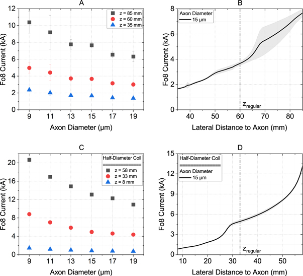
Figure 3. Threshold currents through a Fo8 coil to activate motor neurons in the phrenic nerve. (A) and (C) show an overview of all axon diameters relevant for our experiments, each at the default distance (60 mm for the full-size coil, 33 mm for the half-size coil) and the maximum (+25 mm) and minimum (−25 mm) distances. (B) and (D) show the relationship between threshold current and lateral distance for an exemplary 15 μm thick axon. (A) and (B) represent the values for the regular Fo8 coil described in section Coil properties. For (C) and (D), the coil dimensions have been reduced by 50%. The gray shaded area indicates the variation of the threshold current depending on the exact location of the nodes of Ranvier.
Download figure:
Standard image High-resolution image3.2. Variation of coil diameter
The coil diameter directly affects the generated electric field strength. Smaller coil diameters are interesting from both a cost and handling point of view. We, therefore, investigated the effect of a half-diameter Fo8 coil (95 mm) and a half-diameter RC (47.5 mm). The coil positioning procedure carried out for the full-size coil has been repeated. Smaller coils can be placed closer to the PN, therefore, the default lateral distance has been reduced to zsmall = 33 mm.
Figure 3(C) and (D) show the threshold currents for different axon diameters as a function of the lateral distance for the reduced Fo8 coil. The smaller lateral distance was only partially compensated for by the smaller coil size. This results in threshold currents ranging from 4.4 kA to 8.8 kA. At the minimum lateral distance, the values approached those of the regular-size coil geometry, ranging from 0.7 kA to 1.4 kA.
3.3. Comparison of coil shapes
The experiments described were carried out in the same way for the RC. The ideal positioning was determined analogously to the procedure for the Fo8 coil. A circular coil generates a fundamentally different distribution of the E-field compared to the Fo8 coil, with its field maxima located at the edges of the coil rather than in the center.
Figure 4 shows an overview of the results for a RC. Again, the lowest threshold currents were obtained for small lateral distances and large axon diameters. Compared to the Fo8, the threshold currents were generally lower. For the regular distance of zregular = 60 mm, threshold currents of 2.4 kA to 4 kA were needed to stimulate an axon with a circular coil (figure 4(A) and B). The value increased massively when the coil diameter was reduced and the lateral distance remained the same, as expected. However, when the advantage of the small coil was exploited by moving it to a lateral distance of 8 mm to the axon, the threshold currents dropped to 1.1 kA –2.2 kA (figure 4(C) and (D)).
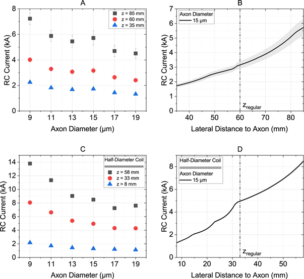
Figure 4. Threshold currents through a round coil to activate motor neurons in the phrenic nerve. (A) and (C) show an overview of all axon diameters relevant for our experiments, each at the default distance (60 mm for the full-size coil, 33 mm for the half-size coil) and the maximum (+25 mm) and minimum (−25 mm) distances. (B) and (D) show the relationship between threshold current and lateral distance for an exemplary 15 μm thick axon. (A) and (B) represent the values for the regular round coil described in section Coil properties. For (C) and (D), the coil dimensions have been reduced by 50%. The gray shaded area indicates the variation of the threshold current depending on the exact location of the nodes of Ranvier.
Download figure:
Standard image High-resolution image3.4. Parameters for the vagus nerve
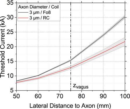
In order to study the effect of stimulation of the vagus nerve, the experiment with the regular-size coil described in section Parameters for the phrenic nerve was repeated with adjusted parameters for axon diameter and lateral distance. Anatomically, the vagus nerve is located deeper in the body than the phrenic nerve, resulting in a default distance of zvagus = 75 mm. Although the vagus nerve itself has a much larger diameter of 4.7 mm [60], the vast majority (60%–80%) of its fibers are C-type fibers with a diameter of 0.4 –2 μm [61], so we simulated axon diameters of 1 μm, 2 μm, and 3 μm.
Figure 5 shows the threshold current through a Fo8 and a RC as a function of the lateral distance between the coil and the axon for an axon with a diameter of 3 μm. 1 μm and 2 μm thick axons of the vagus nerve were only stimulated above our simulation limit of 60 kA and are therefore not depicted. It can be seen that at the standard distance, a coil current of 12.8 kA (RC) and 15.3 kA (Fo8) was required to stimulate the axon. These values are four to five times higher than the threshold current for activation of an axon in the phrenic nerve at the same coil position. Therefore, with the appropriate setting, unwanted stimulation of the vagus nerve can be excluded.
Figure 5. Threshold currents through a Fo8 coil (black) and a RC (red) to activate a 3 μm thick axon as a function of the lateral distance between the coil and the axon. The axon diameters 1 μm and 2 μm are outside the simulation limit of 60 kA and are therefore not shown.
Download figure:
Standard image High-resolution image
4. Discussion
Experimental analysis of phrenic nerve stimulation is challenging and complicated. To reduce the effort and to predict optimal stimulation parameters, simulations are a useful tool. Physiological aspects, such as axon diameter, have large effects on threshold currents [53]. Technical parameters also have a major influence on the stimulation energy required. In order to make magnetic stimulation available and suitable for flexible applications such as rehabilitation, multiple studies have been carried out to increase efficiency and power efficacy [29, 42, 62, 63]. Power requirements for peripheral inductive nerve stimulation are essentially dependent on coil current, coil shape, coil position and distance between the coil and the target nerve. These parameters have been analyzed in several studies [25, 26, 51, 59]. However, most of these simulation studies have considered straight nerves and ideal surroundings. In addition, the importance of parameters such as coil shape and position may vary depending on the application. For more realistic predictions, a detailed analysis of the anatomical conditions for each simulation scenario is required.
In this work, we have applied the findings of the above-mentioned studies to the specific application of phrenic nerve stimulation. With the aim of achieving magnetic nerve stimulation with smaller devices and minimal energy requirements, we investigated the optimal conditions for phrenic nerve stimulation. We analyzed potential coil positions, the relevance of the coil-to-target distance and finally calculated the minimum coil current required for successful stimulation.
4.1. Threshold currents
Our experiments were based on simulations using a typical commercial Fo8 coil and a round coil. We found that coil currents of about 1.4 kA (Fo8) and 1.3 kA (RC) were sufficient to reliably stimulate motor neurons of the phrenic nerve at a nerve-coil distance of 35 mm. When the coils were reduced in size so that they could be positioned closer to the target nerve, the threshold currents increased to 4.4 kA (Fo8) and 4.3 kA (RC) at the same distance. However, when considering the threshold currents at a minimum lateral distance of z = 8 mm, the downsized coil performed much better (i.e., 0.8 kA versus 1.7 kA for Fo8 and 15 μm axon). This is up to a factor of 10 less than TMS equipment can provide.
A study of unilateral magnetic stimulation of the phrenic nerve found that the ideal mean diameter size of the Fo8 coil was 43 mm (per single coil) to reduce stimulation of the adjacent vagus nerve, although vagus nerve activation was not specifically measured [64]. However, the authors only investigated Fo8 coils with diameters between 20 mm and 43 mm. Our simulations with a coil diameter of 47.5 mm show that although smaller coils can be placed closer to the nerve, the electric field generated is reduced, so higher currents are required. The greater proximity to the nerve largely compensated for the increased current requirement. However, smaller coils tend to heat up more quickly, which would force pauses between experiments in real people.
Coil geometries play a central role in magnetic stimulation. In recent years, significant efforts have been made to further improve the performance of coils. Deng et al compared 50 different coil designs, looking for a compromise between penetration depth and focality of the generated E-fields [24]. They concluded that Fo8 coils were more focal compared to circular coils. Focality is certainly an important factor in transcranial brain stimulation, where regions with different functions are located in a confined space. For peripheral nerves, however, the location of stimulation along the nerve is less important. We used one coil with high focality (Fo8) and one with a broader field (RC), which are two of the most commonly used coil shapes in practice. For greater distances (60 mm and 85 mm), the RC showed better performance than the Fo8 coil. This is because the bending of the nerve was the critical factor for stimulation, and therefore the broad peak of the RC with its larger nerve coverage proved to be advantageous. However, for straight nerves, the focal field peak might be a better choice to generate a high field gradient.
There are a number of benefits associated with low coil currents. Stimulators can be designed to be smaller, less complex, and less expensive due to the lower voltage ratings of the components. The size of the coil can also be reduced, allowing for better placement and easier handling. As a result, magnetic stimulators could be more widely accepted in research and especially in clinical practice.
4.2. Stimulation site
We found that under ideal conditions, a coil current of 0.7 kA is sufficient to stimulate the phrenic nerve. However, this value assumes an extremely small nerve-coil distance of only 8 mm, which is difficult to implement in reality. Depending on anatomical constraints, lateral distances of up to 35 mm are quite realistic, requiring currents of 1.3 kA –1.7 kA depending on the thickness of the axon. Fo8 and round coil have performed similarly well for this distance. Naturally, small coil-to-nerve distances are advantageous, but given the curved shape of the nerve and the anatomical model, additional effects determine the current-distance curve. Depending on the coil distance, different electric field components dominate. As a result, the current-distance curves show steeper parts at certain offsets.
Magnetic stimulation of the phrenic nerve is theoretically possible at any point where the magnetic field of the coil reaches the nerve. Stimulation sites known from the literature include the cervical spine [10], the lateral neck [7], and the upper sternum [65]. In cervical magnetic stimulation, a single RC is held over the spinous process of the seventh cervical vertebra so that the magnetic field can reach and stimulate both phrenic nerves. In anterior magnetic stimulation, a RC is positioned centrally over the sternum so that the edge of the coil touches the cricoid cartilage. In our experiments, we chose the lateral neck to ensure the smallest distance between the coil and the phrenic nerve and to maximize the distance to the vagus nerve.
No differences between the left and right phrenic nerve in terms of surface area and myelination along the proximo-distal course of the nerve were observed [47]. Therefore, to reduce computational time, we limited the simulations to unilateral anterolateral stimulation of the right phrenic nerve.
As part of the parasympathetic nervous system, the vagus nerve controls a variety of important bodily functions such as heart rate, mood, immune response, and digestion [66]. Unintentional stimulation must therefore be avoided. We have shown that the anatomical differences between the phrenic nerve and the vagus nerve, together with the appropriate choice of parameters, make it possible to avoid inadvertent stimulation.
4.3. Limitations of the simulation environment
Although it is possible to stimulate the spinal cord directly [67], our model deliberately did not include any parts of the central nervous system. However, given the high threshold currents required for vagus nerve stimulation, we assume that accidental stimulation of CNS axons is highly unlikely.
Although we have recreated and placed the phrenic nerve in as much detail as possible, we have worked with a single nerve fiber in our simulations. In fact, there is considerable individual variation in the structure of the phrenic nerve. The largest of these are the branches of the nerve at its origin in the spinal column at the C4 level. Branching can significantly change the stimulation behavior, especially when individual branches approach the coil or bend at a steep angle.
The interaction between biological tissues and electromagnetic fields highly depends on the dielectric properties of the tissue. Especially the frequency dependence of permittivity and conductivity was subject to numerous studies in the past [68]. There are a number of different specified tissue characterizations that strongly influence the simulation results [69]. The material properties in our work are based on the four-pole Cole-Cole model calculations of Gabriel et al [39]. Using literature data and experiments (electrochemical impedance spectroscopy), they have set up a parametric model of the dielectric properties of biological tissues over a frequency range from 10 Hz to 100 GHz. However, the values for frequencies below 1 MHz are based on literature only and should be used with caution. Although Gabriel et al published another study on low-frequency conductivity 13 years later [70], the permittivity was not reevaluated in this study [71].
For our simulations, we chose a modified RMG model to account for the myelination and motor axon dimensions. More sophisticated approaches, such as the double cable model, may be more accurate for short stimulus durations or rapid successive pulses. However, the threshold predictions of the single cable model are closer to the experimental data and require less computational time [20].
5. Conclusion
We created a simulation environment to study threshold currents for phrenic nerve stimulation at the neck. Using Fo8 and round coils of different sizes, we investigated which parameters could reduce the required coil current. Optimal conditions were achieved with a half-diameter Fo8 coil at a minimum distance of 8 mm. According to our simulation, this configuration allowed stimulation of the phrenic nerve with coil currents below 1 kA. This distance is a lower limit in practice, but also stimulation at z = 35 mm is easily possible, requiring threshold currents of 1.3 kA –1.7 kA for both the Fo8 coil and the RC. Commercially available magnetic stimulation devices are usually designed for currents above 6 kA because they focus on TMS. Smaller, less complex, and more affordable devices with maximum currents of 2 kA can be developed for PMS to make them more attractive for widespread use in intensive care units or rehabilitation. Depending on the individual, smaller coils may be an option to further reduce the lateral distance to the nerve. Unwanted stimulation of the adjacent vagus nerve could be excluded due to its greater distance from the stimulation site and its smaller axon diameter.
Acknowledgments
Funding for this work was granted by the Deutsche Forschungsgemeinschaft (DFG, German Research Foundation), Project number 398820493.
Data availability statement
The data cannot be made publicly available upon publication because they are not available in a format that is sufficiently accessible or reusable by other researchers. The data that support the findings of this study are available upon reasonable request from the authors.