


Abstract
Purpose. To evaluate the impact of CT number calibration and imaging parameter selection on dose calculation accuracy relative to the CT planning process in thoracic treatments for on-board helical CT imaging systems used in helical tomotherapy. Methods and Materials. Direct CT number calibrations were performed with appropriate protocols for each imaging system using an electron density phantom. Large volume and SBRT treatment plans were simulated and optimized for planning CT scans of an anthropomorphic thorax phantom and transferred to registered kVCT and MVCT scans of the phantom as appropriate. Relevant DVH metrics and dose-difference maps were used to evaluate and compare dose calculation accuracy relative to the planning CT based on a variation in imaging parameters applied for the on-board systems. Results. For helical kVCT scans of the thorax phantom, median differences in DVH parameters for the large volume treatment plan were less than ±1% with dose to the target volume either over- or underestimated depending on the imaging parameters utilized for CT number calibration and thorax phantom acquisition. For the lung SBRT plan calculated on helical kVCT scans, median dose differences were up to –2.7% with a more noticeable dependence on parameter selection. For MVCT scans, median dose differences for the large volume plan were within +2% with dose to the target overestimated regardless of the imaging protocol. Conclusion. Accurate dose calculations (median errors of <±1%) using a thorax phantom simulating realistic patient geometry and scatter conditions can be achieved with images acquired with a helical kVCT system on a helical tomotherapy unit. This accuracy is considerably improved relative to that achieved with the MV-based approach. In a clinical setting, careful consideration should be made when selecting appropriate kVCT imaging parameters for this process as dose calculation accuracy was observed to vary with both parameter selection and treatment type.
Export citation and abstract BibTeX RIS

Original content from this work may be used under the terms of the Creative Commons Attribution 4.0 licence. Any further distribution of this work must maintain attribution to the author(s) and the title of the work, journal citation and DOI.
1. Introduction
Temporal and spatial variation in anatomy or physiological changes in tumor biology or function over the course of fractionated treatments can impact the quality of plan delivery in radiation therapy. With the advancement of soft tissue visualization via daily, in-room imaging, adaptive radiotherapy (ART) enables the modification of the original treatment plan to improve the therapeutic ratio through utilization of additional anatomical and functional information derived throughout the treatment course [1]. These modifications may include adjusting the treatment plan contours to account for anatomical variation or adapting the clinical goals and constraints to be more or less aggressive [2]. However, the ability of the treatment planning system (TPS) to perform accurate contour refinement and dose reconstruction depends largely on the ability of the imaging system to sufficiently delineate anatomic structures and provide accurate volumetric information about the anatomy of interest.
Computed tomography (CT) is the most popular methodology to obtain the volumetric information necessary for treatment planning and ART implementation as these images provide a map of the density information for the various tissues as utilized by the TPS. The accuracy of adaptive dose calculation through utilization of on-board cone-beam CT (CBCT) has been reported in the literature [3–6]. These studies showed that, in addition to adequate image quality, accuracy of the CT number to physical or electron density (ED) calibration is required. However, CT numbers (given in Hounsfield Units (HU)) are not constant; rather, they depend on the attenuation properties of the medium as affected by the beam energy and the density and atomic number of the attenuating material. Thus, CT numbers are dependent on parameters such as the tube voltage (in kVp), field-of-view (FOV), scatter conditions, and vendor-specific reconstruction algorithms [7].
For on-board imaging modalities, it is preferable to perform dose calculation using a direct HU-to-ED calibration acquired by scanning a phantom of different material inserts as detailed by Constantinou et al [8]. This approach enables dose recalculation on daily images in a similar manner to dose calculation on planning CT images with no additional corrections for scatter or artifacts needed. Direct CBCT dose calculations using non-stoichiometric calibration methods (based on tissue-equivalent materials in a phantom) have been reported with dose differences relative to that calculated on the planning CT of approximately 1% in phantom studies [4, 9, 10]. However, these studies did not consider the accuracy of dose calculations with this approach in thorax phantoms or for lung cancer patient treatments. Since scatter conditions vary based on the anatomical region of interest, the noticeable photon scatter introduced in thoracic cavity geometries makes dose calculation with CBCT more challenging. For these types of treatments, stoichiometric calibrations (which may be based on biological tissues from previous patient scans) have been reported to be more accurate [11–14]. However, stoichiometric calibrations increase the necessary workload by requiring additional patient scans and accurate segmentation.
Adaptive dose reconstruction in helical tomotherapy treatments has also shown to be feasible through utilization of the megavoltage CT (MVCT) system on TomoTherapy (Accuray, Inc., Sunnyvale, CA) units due to the reliable HU-to-ED calibration curve provided by MVCT imaging techniques [15–17]. Currently, two on-board CT systems are available for use on the next-generation Radixact (Accuray, Inc.) helical tomotherapy system. The Radixact MVCT system is nearly identical to its predecessor on TomoTherapy units; however, one major update is the inclusion of iterative reconstruction (IR) algorithms on the Radixact system in addition to the previously available filtered back-projection (FBP) reconstruction algorithm. The imaging performance of this system has been reported in the literature [18, 19]. A helical kVCT system (brand name ClearRT) mounted nearly orthogonal to the MV beam (the kV tube is at 267.5 degrees when the MV source is at 0 degrees) is also available for clinical use as an optional add-on for Radixact units. This system, released in Spring 2021, is designed to improve overall image quality for the treatment planning and delivery process compared to the MV-based imaging approach [20] and is available for use in research applications at this institution. The performance of this system has recently been characterized in the literature [21–23].
Given the recent clinical release of the ClearRT system, no work has been reported in the literature validating the image fidelity of this system for use in dose reconstruction as has been done for various on-board kV CBCT systems [3–7, 11, 12, 24, 25]. Recall that adaptive dose calculation for thoracic geometries has proven difficult with CBCT without use of time- and resource-intensive stoichiometric calibration methods. Thus, the purpose of this study was to assess the accuracy of dose calculations performed with helical kVCT images of a thorax phantom using non-stoichiometric calibration methods. This accuracy was evaluated relative to doses calculated using diagnostic-quality planning CT images as common in the radiotherapy workflow. A comparison with dose calculation accuracy using MVCT image sets was also performed since the ClearRT system is intended to largely replace MVCT for ART implementation in helical tomotherapy treatments.
2. Methods and materials
2.1. Radixact on-board imaging systems
The ClearRT system contains a kV x-ray source opposite a Cs:Tl flat-panel detector (FPD). Image reconstruction is performed with an FBP algorithm with application of a Hilbert transform filter [20]. The reconstruction algorithm (system version 3.0.1.0 released Spring 2022) also utilizes noise reduction and scatter and lag correction approaches to reduce noise as phantom (or patient) size increases and to improve uniformity in the case of off-centered or inhomogeneous imaging subjects. On this system, the user cannot directly control tube potential (kVp) or time-current product (mAs) settings; rather, the selection of specific protocols specify the scan acquisition parameters as detailed by Tegtmeier et al [22]. Parameter selections for anatomy, body size, mode, and field-of-view (FOV) are available. In short, the selection of anatomy determines the tube potential and reconstructed slice interval, whereas variation in body size adjusts the beam fluence to account for patient size. The FOV determines the visible field size in the axial plane as well as beam filtration and the detector-collimator offset. The mode defines the longitudinal beam width, couch speed, and views per rotation. Variation in this parameter has been observed to have the largest bearing on overall image quality, as application of Fine mode decreases noise and improves contrast relative to Normal and Coarse modes due to a reduction in the longitudinal beam width at isocenter (50 mm for Fine, 100 mm for Normal, ∼140 mm for Coarse) and an increase in views per rotation (which results in a higher mAs for this system–note that body size also impacts the mAs). For additional information on the impact of parameter selection on image quality and patient dose, the reader is referred to the literature [21–23] while for specific values associated with these parameter selections as well as additional information on system specifications, the reader is referred to the Radixact Physics Essentials Guide [20].
The Radixact MVCT system uses a 3.5 MV beam collimated to a width of 4 mm at isocenter with an FOV of approximately 400 mm. The maximum gantry rotation rate improved from 6 rotations per minute (RPM) on TomoTherapy systems to 10 RPM on Radixact. As previously stated, the Radixact system also features additional IR algorithms not available on TomoTherapy. The IR General algorithm is designed to reduce image noise and improve contrast metrics relative to the Standard FBP algorithm while maintaining a similar spatial resolution. The IR Soft Tissue algorithm is designed to further improve noise and contrast at the expense of spatial resolution due to smoothing [20]. The intended impact of each reconstruction algorithm on image quality for this system has been validated in the literature [19, 26]. During image acquisition, the user can select between Fine, Normal, and Coarse scan modes. For this system, mode defines the pitch and couch speed. For each mode, two reconstruction intervals are available (1 and 2 mm for Fine, 2 and 4 mm for Normal, and 3 and 6 mm for Coarse).
2.2. Calibration phantom
The Gammex electron density phantom (Gammex, Middleton, WI) was utilized for HU-to-physical density calibrations. This phantom was previously used to calibrate the planning CT applied in this study (Siemens SOMATOM Definition Edge, Siemens AG, Munich, Germany) and contains inserts for various tissue-substitute rods with diameters of 28.5 mm. Two phantom configurations are available ('head'−20 cm diameter or 'body'−30 cm height by 40 cm width), and the phantom has a depth in the axial plane of 16.5 cm. In this study, the 'body' configuration was used to acquire the calibration data. Calibration curves for the ClearRT system were acquired with Thorax (120 kVp) anatomy protocols, the X-Large body size (to maximize the mA per view), and a 440 mm FOV for Fine and Normal modes. Note that no calibration curve was acquired for Coarse mode, as the increased beam width and relative decrease in mAs/rotation (due to the decrease in views per rotation) resulted in appreciable artifact in the calibration phantom images regardless of the phantom configuration. Additionally, the manufacturer does not require a calibration for Coarse mode to enable the adaptive radiotherapy function, suggesting that this mode is not recommended/necessary for ART implementation. However, dose calculation was still performed on Coarse mode images for a more comprehensive evaluation in an effort to comment on this accuracy (or lack thereof). Axial image slices of the calibration phantom for ClearRT acquisitions are shown in figure 1. Calibration data for the MVCT system was acquired with Fine mode and a 1 mm reconstruction interval for each reconstruction algorithm. For the ClearRT system, the measured section of the density plug must be at least half a beam width away from the longitudinal ends of the phantom [20]. Thus, analysis of mean CT numbers for the tissue-substitute rods was performed with ImageJ software (National Institutes of Health, US) over a scan extension of ∼10 mm for axial slices in the center of the reconstructed phantom images using regions-of-interest (ROIs) of diameter ∼20 mm placed within the inserts.
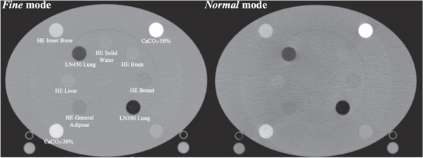
Figure 1. Axial image slices of the Gammex electron density phantom used for CT number to physical density calibration in this study. Shown is the 'body' configuration acquired with Thorax anatomy protocols for the ClearRT system for Fine and Normal modes. Inserts are labelled as appropriate.
Download figure:
Standard image High-resolution image2.3. Anthropomorphic thorax phantom
Dose distributions were calculated for images acquired of the N1 ('LUNGMAN') multipurpose chest phantom (Kyoto Kagaku Corporation, Ltd,. Kyoto, Japan). The phantom includes a main body (chest wall with a girth of ∼100 cm), mediastinum (heart and trachea), pulmonary vessels and bronchus, and a diaphragm. The vessels and soft tissue structures are constructed with polyurethane, while synthetic bones are composed of epoxy resin and calcium carbonate. The substitute materials are designed to have x-ray absorption rates close to those of human tissues, while the chest cavity is designed to simulate realistic scatter conditions. Simulated tumors (urethane foam) of various diameters are also included and can be placed anywhere within the thoracic cavity. In this study, a spherical tumor 12 mm in diameter was placed in the right lung for the small volume plan. Thorax phantom images were acquired with the ClearRT system for Thorax anatomy, X-Large body size, 440 mm FOV, and Fine, Normal, and Coarse mode protocols (note that despite Coarse mode images of the calibration phantom displaying noticeable artifacts as discussed previously, Coarse mode images of the thorax phantom were of sufficient quality for use in this study). Acquisitions with the MVCT system were performed with Fine mode and a 1 mm reconstruction interval for each reconstruction algorithm. The thorax phantom image for the planning CT system was acquired with a high mAs chest protocol at 120 kVp with an FOV of 400 mm. Axial image slices of the thorax phantom for each of the acquisitions described is displayed in figure 2.
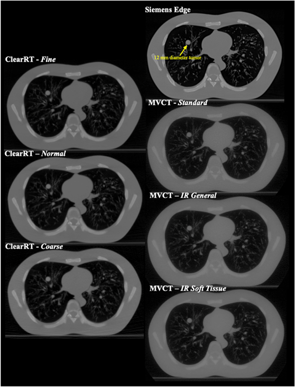
Figure 2. Axial image slices of the anthropomorphic thorax phantom for each of the imaging systems evaluated in the study. The 12 mm diameter spherical tumor is labeled and visible in the right lung.
Download figure:
Standard image High-resolution image2.4. Treatment plan implementation and analysis
All thorax phantom scans were imported into the RayStation treatment planning system (RaySearch Laboratories, Stockholm, Sweden). Treatment plan optimization was performed with the planning CT image and a default dose calculation grid of 0.20 cm. First, an automated external contour was defined using the TPS algorithm utilizing a threshold technique. Artificial target volumes and organs at risk (OARs) were delineated on the phantom scan. A large tumor (clinical target volume (CTV)) was delineated in the left lung consisting solely of lung tissue with a volume of ∼30 cubic centimeters (c.c.). A planning target volume (PTV) was then defined by a uniform 1 cm expansion of the CTV. Delineated OARs included the skin, heart, spinal cord, and right and left lungs. A helical tomotherapy lung treatment of 66 Gy in 33 fractions was simulated and optimized to deliver the prescription to the PTV on the planning CT image. Following rigid registration to the planning CT image set, the target volume and OAR contours were transferred from the planning CT to the ClearRT and MVCT images. Each registration was carefully reviewed to ensure accuracy in this process in accordance with guidelines put forth by the American Association of Physicists in Medicine (AAPM) Task Group 132 [27]. Propagated contours were examined with respect to their target anatomy to ensure proper placement, and these contour volumes were identical throughout all dose calculations. Dose was then recalculated on the Radixact acquisitions with application of the appropriate CT number to density curve by utilizing the treatment delivery optimized on the planning CT (i.e., identical beams/monitor units were delivered). The International Commission on Radiation Units and Measurements (ICRU) Report 83 (2012) suggests defining dose calculation accuracy in intensity-modulated treatments with dose-volume statistics rather than point dose metrics [28], and thus dose-volume histogram (DVH) statistics were used to assess dose calculation accuracy in this study. As dose calculation accuracy was considered in reference to the planning CT, changes in DVH metrics were compared relative to the dose calculations performed on the planning CT images. Additionally, dose-difference maps were used to visually compare calculated dose distributions. For each image of the thorax phantom acquired with the ClearRT system, dose was recomputed utilizing the calibration curves acquired with both Fine and Normal mode to evaluate if the mode used for calibration impacted the accuracy of the dose calculation. For the images acquired with the MVCT system, the calibration specific to each reconstruction algorithm was applied for the corresponding image, though these calibration curves were nearly identical regardless of the reconstruction algorithm (values for all inserts were within ± 10 HU).
Since Velten et al [21] noted that ClearRT acquisitions should not be used for planning of stereotactic treatments due to large effective slice thicknesses and considerable volume averaging in the reconstruction process, it was also deemed of interest to evaluate the impact of smaller target volumes on dose calculation accuracy for this system. Thus, a stereotactic body radiotherapy (SBRT) helical tomotherapy plan with a prescription dose of 50 Gy in 5 fractions was also optimized according to clinical practice. Methods were identical to those discussed for the large volume plan, but in this instance, the CTV encompassed the physical 12 mm urethane foam tumor in the right lung with a volume of less than 1 c.c. The PTV was then defined by an extension of the CTV of 5 mm in the axial plane and 10 mm in the cranial-caudal plane to simulate standard margins used to account for physiological variation in this region. Dose was recomputed on all ClearRT images with application of both the Fine and Normal mode calibrations as before.
3. Results
Density information for the calibration phantom rods as well as mean CT numbers measured for ClearRT acquisitions and entered into the TPS for calibration are shown in table 1. Measured CT numbers for the MVCT systems were all within ±10 HU regardless of the reconstruction algorithm applied, with values for most inserts within ±5 HU. No corrections were applied to the mean CT number values for either imaging system. Note that the CT number for air was acquired with an ROI outside the phantom volume.
Table 1. Measured mean Hounsfield Unit (HU) values for each calibration phantom insert for ClearRT Fine and Normal mode, MVCT (average for all modes), and planning CT acquisitions. The ClearRT calibrations were acquired with Thorax anatomy, X-Large body size, and a field-of-view of 440 mm. Note that only planning CT data acquired for the specific inserts listed is shown.
| Insert | Physical Density (g/c.c.) | Mean HU–Fine mode | Mean HU–Normal mode | Mean HU–MVCT (average) | Mean HU–Planning CT |
|---|---|---|---|---|---|
| Air | 0.001 | −997 | −992 | −1009 | −1000 |
| LN300 Lung | 0.29 | −698 | −673 | −634 | −681 |
| LN450 Lung | 0.45 | −519 | −490 | −478 | −507 |
| HE General Adipose | 0.96 | −60 | −67 | −41 | — |
| HE Breast 50/50 | 0.98 | −13 | 2 | −23 | — |
| HE Solid Water | 1.02 | 11 | 3 | 5 | −5 |
| HE Brain | 1.05 | 43 | 31 | 25 | — |
| HE Liver | 1.08 | 80 | 65 | 47 | — |
| HE Inner Bone | 1.16 | 350 | 334 | 111 | 202 |
| CaCO3%–30% | 1.33 | 519 | 494 | 224 | 420 |
| CaCO3%–50% | 1.56 | 916 | 891 | 380 | 759 |
| Aluminum | 2.71 | 2116 | 2005 | 1070 | — |
3.1. Large volume plan
An axial image displaying isodose lines overlaid on the CTV and PTV contours for the dose calculation with the planning CT thorax phantom image set for the large volume treatment plan is shown in figure 3. Figure 4 shows dose-difference maps for axial image slices (corresponding to that seen in figure 3 for the planning CT) for each ClearRT acquisition and calibration mode evaluated in the study. Tables 2 and 3 show relative and absolute differences in selected target volume and OAR DVH metrics used to assess plan quality for ClearRT in comparison to the planning CT. The most clinically relevant DVH parameters compared for the target volumes (CTV and PTV) were the dose to 98% of the volume (D98, near-minimum dose), D95 (related to the prescription dose), Dmean, and D2 (near-maximum dose), while the most relevant parameters compared for the critical structures (OARs) were Dmean and D2. Additionally, figure 5 shows relative differences for all DVH metrics evaluated (including those listed in table 2 as well as D99, D50, and D1) for the target volumes for each of the ClearRT acquisition modes and calibrations assessed in this study.
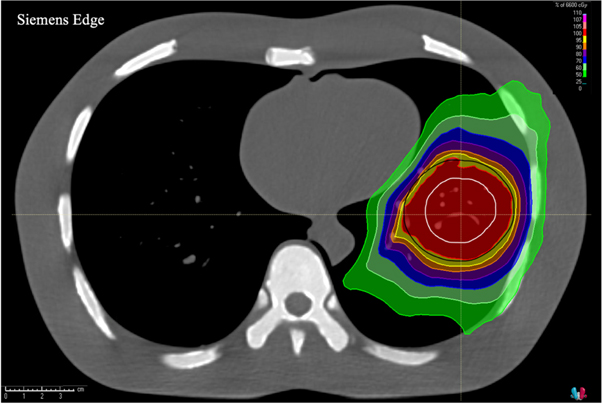
Figure 3. Axial image of the thorax phantom acquired with the planning CT displaying isodose lines calculated for the large volume treatment plan. The CTV (white) and PTV (black) contours are shown as well.
Download figure:
Standard image High-resolution image
Figure 4. Dose-difference maps for each ClearRT acquisition and calibration mode for the large volume treatment plan. The external contour is displayed in green. Differences are shown as the percent difference relative to the prescription dose over the entire treatment course between the ClearRT image set and the planning CT image set (ClearRT minus planning CT). The axial image slices displayed correspond to that of the planning CT shown in figure 3.
Download figure:
Standard image High-resolution imageTable 2. Differences in target volume DVH metrics for ClearRT images of the thorax phantom relative to the planning CT. Values are shown as the percent difference from the planning CT dose for all fractions for the large volume treatment plan.
| Phantom Scan Mode | Calibration Mode | CTV | PTV | Median % Diff | ||||||
|---|---|---|---|---|---|---|---|---|---|---|
| D98 | D95 | Dmean | D2 | D98 | D95 | Dmean | D2 | |||
| Percent Difference from Planning CT Dose | ||||||||||
| Fine | Fine | +0.2 | 0.0 | +0.1 | +0.1 | −0.2 | −0.3 | −0.1 | −0.3 | −0.1 |
| Normal | −0.4 | −0.5 | −0.5 | −0.6 | −1.3 | −1.4 | −0.9 | −1.2 | −0.8 | |
| Normal | Fine | +0.5 | +0.4 | +0.4 | +0.4 | +0.4 | +0.3 | +0.3 | +0.2 | +0.4 |
| Normal | 0.0 | −0.2 | −0.1 | −0.2 | −0.8 | −0.8 | −0.6 | −0.8 | −0.4 | |
| Coarse | Fine | +0.6 | +0.6 | +0.6 | +0.8 | +0.6 | +0.6 | +0.6 | +0.6 | +0.6 |
| Normal | +0.2 | +0.1 | +0.1 | +0.2 | −0.6 | −0.5 | −0.2 | −0.3 | −0.1 | |
Table 3. Differences in OAR DVH metrics for ClearRT images of the thorax phantom relative to the planning CT. Values are shown as the absolute difference from the planning CT dose for all fractions for the large volume treatment plan.
| Phantom Scan Mode | Calibration Mode | Skin | Heart | Spinal Cord | Left Lung | Right Lung | |||||
|---|---|---|---|---|---|---|---|---|---|---|---|
| Dmean | D2 | Dmean | D2 | Dmean | D2 | Dmean | D2 | Dmean | D2 | ||
| Absolute Dose Difference from Planning CT [cGy] | |||||||||||
| Fine | Fine | −3 | −24 | +7 | +14 | −1 | +12 | +3 | +4 | +1 | −1 |
| Normal | −3 | −25 | +9 | +20 | 0 | +18 | +1 | +51 | +1 | −4 | |
| Normal | Fine | −4 | −29 | +5 | +12 | −2 | +10 | +4 | +24 | 0 | +3 |
| Normal | −4 | −28 | +8 | +18 | −1 | +16 | +2 | −31 | 0 | 0 | |
| Coarse | Fine | −6 | −37 | +4 | +7 | −1 | +8 | +5 | +38 | 0 | +2 |
| Normal | −6 | −37 | +6 | +12 | 0 | +15 | +3 | −17 | 0 | −2 | |

Figure 5. Dose relative to the planning CT for all target volume DVH metrics evaluated (n = 7) for the large volume treatment plan for ClearRT images of the thorax phantom with each calibration mode applied.
Download figure:
Standard image High-resolution imageThe differences in calculated target volume DVH parameters for the ClearRT system relative to the planning CT were all within ±1.5% regardless of the mode used for the thorax phantom acquisition or the mode used to acquire the calibration curve, while nearly 40% of DVH parameters were within ±0.5% (18 of 48). The median difference between target volume dose parameters was smallest for the Fine mode thorax phantom acquisition with the Fine mode calibration (med: −0.1%, min: −0.3%, max: +0.2%) and the Coarse mode thorax phantom acquisition with the Normal mode calibration (med: −0.1%, min: −0.6, max: +0.2). Note that the dose difference for Coarse mode being lower with the Normal mode calibration as compared to the Fine mode calibration is likely a result of Coarse mode image acquisition parameters being more similar to Normal mode. Overall, application of the Fine mode calibration resulted in slightly 'hot' (higher dose) target volume dose distributions relative to the planning CT, while application of the Normal mode calibration resulted in slightly 'cold' (lower dose) dose distributions as observed in figures 4 and 5. DVH parameters for the OARs were generally 'hot' relative the planning CT with the exception of the dose to the skin. For the skin, differences of over 20 cGy over the entire treatment course were observed for the D2 parameter as shown in table 3. However, doses were well within those specified in the clinical goals utilized during the plan optimization process, and thus these values would not be a concern clinically for this particular treatment plan.
Figure 6 shows dose-difference maps for axial image slices (corresponding to that seen in figure 3 for the planning CT) for each MVCT acquisition and reconstruction algorithm evaluated in the study. Tables 4 and 5 show relative and absolute differences in the selected DVH metrics for the Radixact MVCT system in comparison to the planning CT. Figure 7 shows relative differences for all target volume DVH metrics evaluated for each reconstruction algorithm available on the MVCT system.

Figure 6. Dose-difference maps for each MVCT acquisition and reconstruction algorithm for the large volume treatment plan. The external contour is displayed in green. Differences are shown as the percent difference relative to the prescription dose over the entire treatment course between the MVCT image set and the planning CT image set (MVCT minus planning CT). The axial image slices displayed correspond to that of the planning CT shown in figure 3.
Download figure:
Standard image High-resolution imageTable 4. Differences in target volume DVH metrics for Radixact MVCT images of the thorax phantom relative to the planning CT. Values are shown as the percent difference from the planning CT dose for all fractions for the large volume treatment plan.
| Reconstruction Algorithm | CTV | PTV | Median % Diff | ||||||
|---|---|---|---|---|---|---|---|---|---|
| D98 | D95 | Dmean | D2 | D98 | D95 | Dmean | D2 | ||
| Percent Difference from Planning CT Dose | |||||||||
| Standard | +1.4 | +1.3 | +1.4 | +1.9 | +2.0 | +1.9 | +1.7 | +2.2 | +1.8 |
| IR General | +1.3 | +1.2 | +1.4 | +1.9 | +2.1 | +2.0 | +1.8 | +2.3 | +1.9 |
| IR Soft Tissue | +1.3 | +1.2 | +1.4 | +1.9 | +2.1 | +1.9 | +1.8 | +2.2 | +1.9 |
Table 5. Differences in OAR DVH metrics for Radixact MVCT images of the thorax phantom relative to the planning CT. Values are shown as the absolute difference from the planning CT dose for all fractions for the large volume treatment plan.
| Reconstruction Algorithm | Skin | Heart | Spinal Cord | Left Lung | Right Lung | |||||
|---|---|---|---|---|---|---|---|---|---|---|
| Dmean | D2 | Dmean | D2 | Dmean | D2 | Dmean | D2 | Dmean | D2 | |
| Absolute Dose Difference from Planning CT [cGy] | ||||||||||
| Standard | +7 | +1 | +12 | +26 | +3 | +28 | +13 | +127 | +4 | +31 |
| IR General | +5 | −2 | +7 | +16 | 0 | +16 | +12 | +132 | +3 | +29 |
| IR Soft Tissue | +6 | −2 | +7 | +16 | 0 | +16 | +12 | +130 | +3 | +29 |

Figure 7. Dose relative to the planning CT for all target volume DVH metrics evaluated (n = 7) for the large volume treatment plan for Radixact MVCT images of the thorax phantom.
Download figure:
Standard image High-resolution imageDose differences relative to the planning CT for the MVCT acquisitions were noticeably higher than those observed for the ClearRT system, with median differences of nearly +2.0% regardless of the reconstruction algorithm applied as shown in table 4. All dose distributions for the MVCT images were considerably 'hotter' than that for the planning CT image as observed in figures 6 and 7. While differences in skin dose were reduced when compared to the ClearRT system, differences for the lung DVH metrics were greatly increased as hot spots of over 1 Gy in magnitude relative to the planning CT were observed in the left lung according to the D2 metric as shown in table 5. For this analysis, the selection of the reconstruction algorithm had little bearing on the relative accuracy of the dose calculation.
3.2. Lung SBRT plan
An axial image displaying isodose lines for the dose calculation with the planning CT thorax phantom image set for the lung SBRT treatment plan is shown in figure 8. Figure 9 shows dose-difference maps for axial image slices (corresponding to that seen in figure 8 for the planning CT) for each ClearRT acquisition and calibration mode evaluated in the study. Tables 6 and 7 show relative and absolute differences in selected target volume and OAR DVH metrics used to assess plan quality for ClearRT in comparison to the planning CT. Finally, figure 10 shows relative differences for all DVH metrics evaluated for the target volumes for each of the ClearRT acquisition modes and calibrations assessed in this study.

Figure 8. Axial image of the thorax phantom acquired with the planning CT displaying isodose lines calculated for the lung SBRT treatment plan. The maximum dose point of 64.87 Gy is denoted by the red cross.
Download figure:
Standard image High-resolution image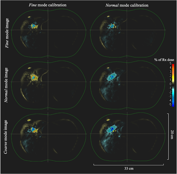
Figure 9. Dose-difference maps for each ClearRT acquisition and calibration mode for the lung SBRT treatment plan. The external contour is displayed in green. Differences are shown as the percent difference relative to the prescription dose over the entire treatment course between the ClearRT image set and the planning CT image set (ClearRT minus planning CT). The axial image slices displayed correspond to that of the planning CT shown in figure 8.
Download figure:
Standard image High-resolution imageTable 6. Differences in target volume DVH metrics for ClearRT images of the thorax phantom relative to the planning CT. Values are shown as the percent difference from the planning CT dose for all fractions for the lung SBRT treatment plan.
| Phantom Scan Mode | Calibration Mode | CTV | PTV | Median % Diff | ||||||
|---|---|---|---|---|---|---|---|---|---|---|
| D98 | D95 | Dmean | D2 | D98 | D95 | Dmean | D2 | |||
| Percent Difference from Planning CT Dose | ||||||||||
| Fine | Fine | −0.2 | −0.1 | −0.8 | −0.7 | −1.1 | −0.9 | +0.6 | −1.3 | −0.8 |
| Normal | −2.2 | −2.1 | −2.0 | −1.2 | −1.9 | −1.2 | +0.3 | −2.0 | −2.0 | |
| Normal | Fine | −1.7 | −1.7 | −1.3 | −1.2 | +0.6 | +1.2 | +1.2 | −1.1 | −1.2 |
| Normal | −3.6 | −3.6 | −2.4 | −1.5 | −3.7 | −2.7 | −0.9 | −2.2 | −2.6 | |
| Coarse | Fine | −4.6 | −4.2 | −2.3 | −1.6 | +0.7 | +0.7 | +0.9 | −1.7 | −1.7 |
| Normal | −6.6 | −6.1 | −4.5 | −2.1 | −1.2 | −1.9 | −1.6 | −3.3 | −2.7 | |
Table 7. Differences in OAR DVH metrics for ClearRT images of the thorax phantom relative to the planning CT. Values are shown as the absolute difference from the planning CT dose for all fractions for the lung SBRT treatment plan.
| Phantom Scan Mode | Calibration Mode | Skin | Heart | Spinal Cord | Left Lung | Right Lung | |||||
|---|---|---|---|---|---|---|---|---|---|---|---|
| Dmean | D2 | Dmean | D2 | Dmean | D2 | Dmean | D2 | Dmean | D2 | ||
| Absolute Dose Difference from Planning CT [cGy] | |||||||||||
| Fine | Fine | −1 | −5 | 0 | +1 | 0 | 0 | 0 | 0 | 0 | +1 |
| Normal | −1 | −7 | +1 | +4 | 0 | 0 | +1 | 0 | 0 | +1 | |
| Normal | Fine | −2 | −5 | 0 | 0 | 0 | +3 | 0 | +1 | +1 | +1 |
| Normal | −2 | −7 | +1 | +3 | 0 | +5 | 0 | 0 | 0 | +1 | |
| Coarse | Fine | −3 | −3 | 0 | +1 | +1 | +5 | 0 | 0 | 0 | +1 |
| Normal | −3 | −6 | 0 | +2 | +1 | +5 | +1 | 0 | 0 | +1 | |

Figure 10. Dose relative to the planning CT for all target volume DVH metrics evaluated (n = 7) for the lung SBRT treatment plan for ClearRT images of the thorax phantom with each calibration mode applied.
Download figure:
Standard image High-resolution image
All calculated target volume DVH parameters in table 6 for the Fine mode image utilizing the Fine mode and Normal mode calibrations were within ±1.3% (median −0.8%) and ±2.2% (median −2.0%) of the planning CT, respectively, while all target volume parameters for the Normal mode image utilizing the Fine mode and Normal mode calibrations were within ±1.7% (median −1.2%) and ±3.7% (median −2.6%), respectively. For the Coarse mode image with the Fine mode and Normal mode calibrations, target volume parameters were within ±4.6% (median −1.7%) and ±6.6% (median −2.7%), respectively. Overall, dose distributions in the target volumes were 'colder' for the ClearRT acquisitions regardless of phantom image or calibration parameters, signifying that dose was underestimated for a majority of the metrics in table 6 (∼83%, 40 of 48). In general, for this plan the differences between target volume DVH metrics relative to the planning CT were lessened with application of the Fine mode calibration regardless of the mode used for the acquisition of the thorax phantom. For the eight target volume DVH parameters for each of the three thorax phantom acquisition modes in table 6, the Fine mode calibration resulted in a lower percent error in ∼92% of metrics (22 of 24) compared to the Normal mode calibration.
As with the large volume treatment plan, DVH parameters for the OARs were generally 'hot' relative to the planning CT with the exception of the skin as shown in table 7. Given the nature of this treatment plan in which the optimizer allowed for dose delivery to a small treatment volume, absolute dose differences relative to the planning CT for the OARs were nearly negligible. As with the large volume treatment plan, these values were well within those specified for clinical goals and tolerances during the optimization process.
4. Discussion
Dose calculations with ClearRT images showed good agreement (median errors of <1%) with dose calculated on the planning CT for a helical tomotherapy large volume lung plan simulated with a thorax phantom. Dose calculation accuracy when compared to the planning CT was also improved relative to the MV-based approach available on Radixact systems, likely due to the noticeable improvement in image quality for ClearRT as presented in the literature [21, 22]. For the MVCT scans, dose calculation accuracy was notably not dependent on the reconstruction algorithm applied when acquiring images of the thorax phantom; however, the impact of image quality on target delineation and contouring as necessary for ART implementation was not evaluated in this study as ROIs were copied from the planning CT following rigid registration. The impact of image quality on image registration was also not fully evaluated as no anatomical variation was observed in this study due to use of a static phantom and deformable image registration was not applied. It is likely that the selection of reconstruction algorithm would impact these processes in a clinical setting to some extent. It is important to clarify that dose calculation accuracy in this study was considered relative to that calculated on the planning CT, as comparison to this 'original' dose calculation is an important aspect of the adaptive radiotherapy workflow. The authors do not intend to imply that the dose distribution as calculated on the planning CT is necessarily the 'gold standard' in that, more so than the other data sets, it accurately represents what is actually delivered to the patient. The MVCT imaging system does indeed sample the phantom using an energy much closer to that of the therapy beam and theoretically could provide information that more closely resembles what should be used for planning. However, due to the much-improved image quality for diagnostic-quality CT simulation systems and the corresponding benefits in target and OAR delineation, these image sets are the standard on which the original treatment plans are computed and thus all comparisons in this study were relative to the dose calculated for the planning CT images.
Additionally, for most imaging and calibration conditions in this study, the results for ClearRT showed improved accuracy compared to previously published methods for CBCT-based dose calculation in lung treatments in which median errors of 2% or less were observed [4, 5, 25, 29, 30]. It is important to note that several of these studies included comparison with treatment plans of actual lung cancer patients as opposed to a static thorax phantom as utilized in this study, and thus uncertainty due to variation in patient anatomy and physiological motion must be considered as well. However, many of these previously reported studies also required time- and resource-intensive calibrations, artifact or scatter correction, and density overrides to account for the limited FOV present in many CBCT images, while this study with the ClearRT system required no additional effort outside of the initial calibration.
For a small volume lung SBRT treatment plan, dose calculation errors were considerably larger than those observed for the large volume plan, while the accuracy appeared more dependent on the parameters utilized during HU-to-ED calibration and acquisition of the thorax phantom. The reconstruction interval for ClearRT images utilizing Thorax anatomy protocols is 1.8 mm and meets the recommended tolerance of <3 mm [31] and the desirable spacing of <2 mm [32] for SBRT treatment planning. However, the nominal slice thickness is 3.6 mm, meaning that the data acquisition volumes of two adjacent slices overlap each other by 50%, resulting in appreciable volume averaging in the reconstruction process. As noted by Velten et al, careful consideration should be made before implementing this system in clinical SBRT treatments due to the possible reduction of accuracy in identifying and delineating small structures, especially in instances of fine detail requirements in the target anatomy [21].
This study also provides insight into parameter selection for both image acquisition and CT number to density calibration to minimize uncertainty in dose calculation relative to the planning CT for the ClearRT system. For the large volume plan, dose calculation accuracy was largely independent of the selected parameters; however, it is necessary to reiterate that the impact of variable image quality (due to variation in imaging parameters) on image registration and recontouring was not considered to the full extent in this study. For the lung SBRT plan, the use of Fine mode for both calibration and thorax phantom imaging provided the smallest dose differences in the treatment plan. In a clinical setting, it is also important to consider the trade-off between image quality, patient dose, and scan acquisition time when selecting protocols for use in ART. The impact of parameter selection on these considerations has been noted by Tegtmeier et al [22, 23].
There are several additional considerations regarding future work and clinical implementation. First, only thorax anatomy was considered in this study. Given that, for a given change in CT number or relative electron density, a larger variation in dose is observed for greater tissue thickness than for reduced tissue thickness, the impact of CT number accuracy (and calibration) on dose calculation accuracy varies for different anatomical sites [33, 34]. Similar studies with CBCT systems have confirmed the dependence of dose calculation accuracy on the anatomical region of interest. As a result, further ClearRT studies should be performed for additional body sites to test the results in comparison with the thoracic region.
Next, while no corrections were applied to the calibration data in this study and direct, non-stoichiometric calibrations were used, future investigation of these approaches may show that the reported errors can be further minimized through more deliberate calibration with appropriate correction techniques. It is also suggested by the manufacturer that real water may be a useful reference in the calibration process and recommended that tissue-substitute materials in the +/− 100 HU range not be used. However, the goal of this study was to isolate the potential impact of image quality variation as a result of parameter selection on dose calculation accuracy for the ClearRT system and not to perform a comprehensive clinical commissioning process. As a result, the image acquisition and calibration process were kept identical to that used for the CT simulator as needed for dose calculation with the RayStation TPS. Given the status of the available ClearRT system at this institution (research-only), the full adaptive radiation therapy workflow cannot be evaluated at this time and thus the full extent of ART implementation cannot be considered in this study. Regardless, the results of this study suggest that accurate dose calculations in the thoracic region can be performed on images acquired with the ClearRT system without any additional time and effort required for the calibration process relative to that performed for the planning CT.
It is important to reiterate that the targets simulated in the left and right lungs were located in a region susceptible to physiological motion. In a clinical setting, these cases would be simulated with consideration of recommendations provided by AAPM Task Group 76 on the management of respiratory motion in radiation oncology [35], including acquisition of a 4DCT and breathing trace. Note that the Radixact system also includes Synchrony®, an intrafraction motion tracking system for helical tomotherapy treatments. This technology synchronizes the movement of the radiation beam with the respiratory motion of the target through use of kV radiographs of the target and LEDs placed on the patient's chest. The tracking and dosimetric accuracy of this system has been previously studied [36, 37]. As the goal of this current study was to evaluate the impact of image quality on dosimetric accuracy for the ClearRT system and not the impact of target motion, a static phantom and target was utilized to remove the impact of other variables on the evaluation. However, the latter is an important consideration as well warranting future investigation.
It is recommended by the International Atomic Energy Agency (IAEA) that parameters used for HU-to-ED calibration should match those intended to be used clinically to minimize uncertainty due to HU variation across different scan protocols [38]. While the selection of mode for density calibration and thorax phantom acquisition with ClearRT had little bearing on dose calculation accuracy for the large volume treatment plan in this particular study, recall that previous studies have suggested a noticeable variation in image quality based on changes to this imaging parameter [21–23]. In a clinical setting, it may prove beneficial to limit the mode used in ART implementation to that which produces the best image quality (Fine) if a single calibration is to be used or provide separate calibrations to minimize uncertainty in HU variation if it is intended that mode be varied from treatment to treatment. While similar dose calculation was achieved (especially for the large volume treatment plan) regardless of the ClearRT mode used for calibration and image acquisition, previous work has suggested that HU variation is more prominent for protocols using either Normal or Coarse mode and thus this additional uncertainty should be considered along with the IAEA recommendation when implementing this system clinically.
5. Conclusion
This work provides an initial investigation into the accuracy of dose calculations in the thoracic region utilizing images acquired with the ClearRT system on the Radixact helical tomotherapy unit and is a necessary step toward the implementation of adaptive planning in the clinic utilizing this modality. In addition to superior image quality provided by this system when compared to on-board CBCT and MVCT systems, the results of this study demonstrate that accurate dose calculation in thorax phantom plans (relative to that for diagnostic-quality planning CT scans) can be achieved with ClearRT images without correction techniques in the calibration process as commonly needed with CBCT systems and without limitations in soft tissue contrast as observed in MVCT implementation. Due to the more pronounced impact of volume averaging for ClearRT images of small objects, careful consideration should be made before implementing this system in patient SBRT treatments. Additionally, the selection of imaging parameters in the image acquisition and CT number to density calibration processes is an important consideration. In general, parameters used for calibration should match those intended to be utilized clinically per IAEA recommendations. Future studies on actual patient treatment plans and for a wider range of anatomical regions are required to comment on dose calculation accuracy specific to additional body sites as the impact of CT number accuracy and image quality on dose calculation accuracy varies with tissue thickness and composition.
Acknowledgments
The authors express their gratitude to the students and staff of the UWMRRC for their support of this project, as well as customers of the UWRCL and UWADCL who help fund ongoing student research at the UWMRRC. Additional thanks are extended to Accuray, Inc. for their technical support during this work.
Data availability statement
The data that support the findings of this study are available upon reasonable request from the authors.
Conflict of interest
John E. Bayouth has ownership interest in MR Guidance, LLC, which has business activity with a company that also utilizes image-guided radiation therapy technology (ViewRay, Inc.). Additionally, while this project received no external funding, the data was collected on a Radixact system (Accuracy, Inc.) provided to UW-Madison under a research agreement (Bayouth, PI) and Jessica R. Miller has research funding support from Siemens Medical Solutions.