

Abstract
Accurate radiation dosimetry is required for radiation protection in various environments. Therefore, dosemeters and dose-rate meters must be calibrated in standard radiation fields. The National Metrology Institute of Japan (NMIJ) expands the energy range of x-ray reference field measurement up to 450 kV using a cylindrical graphite-walled cavity ionization chamber. Departure from the condition of the Spencer-Attix cavity theory was evaluated by comparing the measurement results obtained using the cavity ionization and the free-air ionization chambers, which are used as the primary standard up to a tube voltage of 250 kV. The calibration coefficients found using the spherical ionization chamber were in good agreement with those obtained by the free-air ionization chamber within relative standard uncertainties (k = 1) for N-200 and N-250 x-ray fields. Consistent calibration coefficients were obtained in the energy range 300–450 kV.
Export citation and abstract BibTeX RIS

Original content from this work may be used under the terms of the Creative Commons Attribution 4.0 licence. Any further distribution of this work must maintain attribution to the author(s) and the title of the work, journal citation and DOI.
1. Introduction
Although radiation is broadly utilized in industrial, medical, and agricultural fields, users risk radiation exposure unless they protect themselves appropriately. Thus, dosemeter calibration is necessary to perform accurate dose measurement since the result can vary depending on the material and shape of the detection unit.
Generally, dosemeters for radiation protection are calibrated by x-ray standards of up to ∼210 keV using a primary standard consisting of an x-ray tube with a tube voltage of 250 kV and a free-air ionization chamber. For higher enrgies, a gamma-ray standard with mean energies of 662 keV and 1.25 MeV, consisting of radionuclides Cs-137 and Co-60, respectively, and the graphite-walled cavity ionization chamber are used. Air kerma measurements require that the secondary charged particle equilibrium is sufficiently approached within the effective volume of the ionization chamber. To achieve it using a free-air ionization chamber, its ambient air volume must be larger than the range of secondary charged particles, which are mainly electrons in the case of x-ray irradiation. However, a huge free-air chamber is needed for an x-ray above 300 keV since the maximum range of the secondary electrons in air is more than 79 cm, which is difficult to builid. Nevertheless, the Physikalisch Technische Bundesanstalt (PTB) in Germany and the National Institute of Metrology (NIM) in China have already developed calibration systems with tube voltages above 300 kV. The PTB has a large parallel-plate free-air chamber (PK400), which can measure air kerma up to an x-ray field of 400 kV (Ankerhold 2007). The NIM performed the first air kerma measurement of up to 450 kV with a spherical graphite cavity ionization chamber, which is originally used for the gamma-ray standard (Zhao et al 2021).
The NMIJ also expanded the energy range of x-ray reference fields up to 450 kV by applying a cylindrical graphite-walled cavity ionization chamber. The mean restricted mass electronic stopping power ratio of graphite to dry air is one of the most important factors in terms of air kerma measurement using the graphite-walled cavity ionization chamber. The stopping power ratio is calculated in the numerical simulation based on the Spencer–Attix schematization of Bragg–Gray cavity theory (Gray 1936, Spencer and Attix 1955, Nahum 1978). Comparison between the different primary standards was performed, which approached the validation of the Spencer-Attix cavity theory in the medium-hard x-ray energy range. Furthermore, values of the stopping power ratio calculated from numerical simulations based on x-ray fluence spectra were compared with the corresponding experimental values. Finally, the commercial cavity ionization chamber was calibrated within a wide energy range including x-rayx-rays of the conventional tube voltages (60–250 kV) and gamma-rays (Cs-137 and Co-60) for verification of the NMIJ's new qualities above 300 kV.
Buermann and Hilgers (2007) also obtained values of the stopping power ratio from the comparison between the use of free air ionization and graphite-walled cavity ionization chambers and from the numerical simulations in the x-ray fields with tube voltages ranging from 300 to 400 kV at the PTB. The calculated values were obtained with graphite's mean excitation energy (I-value) of 78 eV, which is recommended in ICRU report 37 (Berger et al 1984). They concluded that the difference between experimental and simulation results was caused by incorrect stopping power values, and the experimental values corresponded to that computed with an I-value of 86 eV. In this work, the stoppinng power ratio is calculated using an I-value of 81.0 eV, as recommended in ICRU report 90 (Seltzer et al 2016), and the validity of the results was discussed.
2. Materials and methods
a. X-ray facility
Air kerma measurements were performed in the medium-hard x-ray facility of the NMIJ. The x-ray tube (MG452, YXLON international K.K.) had a 5-mm beryllium window and a tungsten anode was attached at an angle of 30° to the electron beam. The maximum anode load was 4.5 kW. Applied tube voltages were varied from 20 kV to 450 kV in steps of 20 V. The generated x-ray formed a uniform dose field with a diameter of 40 cm at 3.0 m of distance from the source through a collimation unit.
b. Free-air ionization chamber
The parallel-plate free-air chamber for the medium-hard x-ray standard was designed for air kerma measurement with a tube voltage of up to 250 kV. The dimensions of the free-air chamber are listed in table 1 (Kurosawa and Takata 2005a). For the free-air chamber, the air kerma rate ( ) in the effective volume
  was determined by
where  is the measured current,
  is the density of the dry air at reference condition (293.15 K and 1013.25 hPa),
  is the mean energy required to produce an ion pair in the dry air,
  is the elementary charge,
  is the mean bremsstrahlung correction value, and
  is the correction factor to the ideal condition for air kerma measurement using the free-air chamber. The main correction factors, except for the correction of the humidity effect, are listed in table 2.
Table 1. Dimension of the NMIJ free-air chamber.
| Attenuation length (cm) | 37.2 |
|---|---|
| Collector length (cm) | 10.0 |
| Electrode separation (cm) | 24.0 |
| Electrode width (cm) | 23.0 |
| Aperture diameter (cm) | 2.50 |
| Effective volume (cm3) | 49.042 |
| Applied voltage (V) | 4000 |
Table 2. Main correction factors for air kerma measurement by the NMIJ free-air chamber.
| N-150 | N-200 | N-250 | |
|---|---|---|---|
| Air attenuation | 1.0071 | 1.0063 | 1.0059 |
| Photon scatter | 0.9967 | 0.9972 | 0.9976 |
| Electron loss | 1.0040 | 1.0074 | 1.0055 |
| Aperture edge transmission | 0.9996 | 0.9991 | 0.9985 |
| Aperture scatter | 0.9987 | 0.9985 | 0.9977 |
| Field distortion | 1.00035 | 1.00035 | 1.00035 |
| Polarity | 0.99985 | 0.99985 | 0.99985 |
 and initial ionization and initial ionization | 0.9983 | 0.9989 | 0.9992 |
c. Graphite-walled cavity ionization chamber
The graphite-walled cavity ionization chamber was cylindrical with a wall thickness of 2 mm, which was also used as a primary gamma ray standard with Cs-137 gamma rays. Its dimensions are listed in table 3 (Kurosawa et al
2005b). According to the cavity theory developed by Spencer and Attix, the air kerma rate in cavity volume  was determined by the following equation (Gray 1936, Spencer and Attix 1955, Nahum 1978):
where  is the mean mass energy absorption coefficient of graphite to dry air,
  is the mean restricted mass electronic stopping power ratio of dry air to graphite with the cutoff energy,
  and
and  are correction factors to the ideal condition for air kerma measurement by the cavity chamber. The average absolute current for both polarities was used as the output.
Table 3. Dimensions of the cylindrical graphite cavity chamber.
| Inner height (mm) | 50 |
|---|---|
| Inner diameter (mm) | 40 |
| Graphite wall thickness (mm) | 2 |
| Density of graphite wall (g/cm3) | 1.85 |
| Electrode diameter (mm) | 2.0 |
| Electrode length (mm) | 1.4 |
| Cavity volume (cm3) | 62.6984 |
| Applied voltage (V) | ±1200 |
The  was determined from energy fluence spectrum of photon field by the following equation:
where E is the photon energy,  is the fluence spectrum in the photon field,
  is the mass energy absorbtion coefficient. The data of mass enegy absormbtion coefficient in each medium
  refered to the NIST Standard Reference database (Hubbell and Seltzer 1995).
Under the condition that the Spencer-Attix cavity theory holds,  was determined by the following equation (Spencer and Attix 1955, Nahum 1978):
where E is the electron kinetic energy through the cavity,  is the fluence spectrum of electrons,
  is the restricted mass electronic stopping power, and
  is the mass unrestricted electronic stopping power in each material.
  was calculated using the graphite's excitation energy of 81.0 ± 1.8 eV based on ICRU report 90 (Seltzer et al
2016). The cutoff energy
was calculated using the graphite's excitation energy of 81.0 ± 1.8 eV based on ICRU report 90 (Seltzer et al
2016). The cutoff energy  is the mean energy of the secondary electrons that cross the cavity and is closely approximated to the mean energy of electrons that have the same residual range in air as the mean chord length
  in the cavity. It is expressed by the simple formula,
  where V is the cavity volume and S is its surface area (Rogers and Kawrakow 2003). For the NMIJ's cylindrical graphite-walled cavity ionization chamber, the value of
  is 40.5 keV.
The  includes the following correction factors:
- (a)Effect in wall material,
 The wall corretion of scattering and attenuation in the graphite wall of the cavity chamber was calculated using Monte-Carlo simulation (Kurosawa et al
2005b).
The wall corretion of scattering and attenuation in the graphite wall of the cavity chamber was calculated using Monte-Carlo simulation (Kurosawa et al
2005b). - (b)Nonuniformity of the photon field,
The nonuniformity correction at NMIJ was taken as the ratio between the deposition energies in the air of the chamber when it was placed in a uniform parallel photon field and when it was placed a distance from a point source (Rogers and Treurniet 1999).
- (c)Departue from the condition of the Spancer-Attix cavity theory
The correction factor relates to the calculation of the and these calculation method is described in the section 2.5.
- (d)Electric charge loss due to recombination and diffusion,
The correction for electric charge losses due to recombination and diffusion was determined by the Boutillon's method (Boutillon 1998).
- (e)Contribution of scattering photons from ionization chamber stem,
The contribution of the stem scattering was experimantally determined as the ratio of signal currents measured with and without a dummy stem on the top of the chamber.
- (f)Deviation of ionization due to humidity,
The value of the humidity correction was obtained by curve fitting of ICRU report 31 data that is a cavity chamber current depending on relative humidity at 20℃ and 1013.25 Pa (Bichsel et al
1979).
- (g)Deviation related to the-value, and


The values of the  -value corretions were obtained to be fluence weighted mean values with fitting data of ICRU report 90 (Seltzer et al
2016).
-value corretions were obtained to be fluence weighted mean values with fitting data of ICRU report 90 (Seltzer et al
2016).
The values of (a) and (b) were calculated by the numerical simulation using EGS5 (Electron Gamma Shower version 5) code for the Monte Carlo simulation of the coupled transport of electrons and photons (Hirayama et al 2005). All measurements by the cylindrical graphite-walled cavity ionization chamber were made for the x-ray incident angle of 90°.
d. X-ray fluence spectra
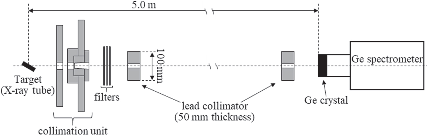
To calculate the correction factors of the graphite-walled cavity ionization chamber, it is necessary to obtain a fluence spectrum from each x-ray quality. Pulse height spectra were measured using broad-energy germanium (BEGe) detector BE2020 with an active volume of 44.00 cm3 and 0.6 mm-thick carbon entrance window manufactured by Mirion Technologies (Canberra) K.K. To prevent a pile-up of signals from the BEGe detector, x-ray tube current was adjusted to <0.1 mA, and two lead collimators with a 5 mm diameter pinhole were placed as shown in figure 1. The two collimators were far enough to ensure that almost no scattering photons from the first collimator reached the sensitive part of the detector, and photons that reached the sensitive part were almost parallel beams. The pulse height spectra were obtained from the data set of the following two measurements for the same live time of the BEGe detector:
- (i)Measurement using two separated collimators with a pinhole, as shown in figure 1;
- (ii)Measurement using a lead block with a non-hole and of the same size replaced from the collimator in front of the BEGe spectrometer.
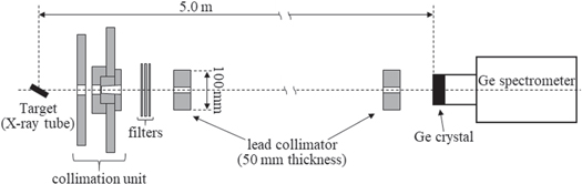
Figure 1. Experimental setup using two collimators with a 5 mm diameter pinhole for pulse height measurement of x-ray qualities at the NMIJ using a Ge spectrometer.
Download figure:
Standard image High-resolution imageThe pulse height spectrum in (i) includes photon counts from the x-ray source through filters and photons scattered from the second collimator and background, whereas the pulse height spectrum in (ii) does not measure photon counts from the source. Therefore, the pulse height spectrum including only the photons from the source was obtained by subtracting the counts of (ii) from those of (i). The pulse height spectra were obtained in 2048 channels and then rebinned into 225 channels having channel width of 2 keV.
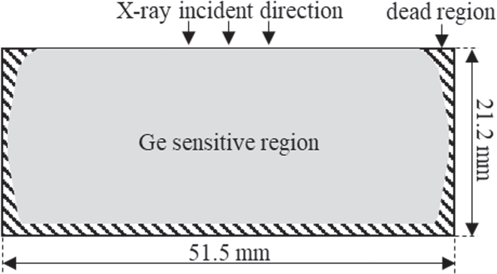
Furthermore, the unfolding method was applied to reduce counts from interactions in the Ge crystal using the response matrix calculated by the numerical simulation with the EGS5 code. The calculation of the response matrix requires details of the Ge crystal geometry, including sensitive and insensitive (dead) regions. The geometry was estimated from the comparison of detection efficiency between experiments with radionuclides Am-241, Ba-133, and Cs-137 and simulations. The dead layer thickness was determined by mean interaction depths in each incident photon energy from the radionuclides (Petit et al
2006). The geometry that best matches the experimental data had a thick dead region at the edges of the crystal, as shown in figure 2. The Ge crystal had an active diameter from 43.5 to 50.1 mm, an active length of 19.9 ± 0.1 mm, and a front dead layer of 15.2 ± 0.2 μm. The relationship between the fluence spectrum  and pulse height spectrum
  in each channel (L) was denoted by

where  is the response matrix for each monoenergetic photon up to 450 keV (225 columns and 225 rows). The response matrix was calculated with the EGS5 using the detailed Ge crystal geometry. The determinant of equation (5) can be written by the following equation :


Therefore, the fluence spectrum was obtained by sequentially subtracting the pulse height component from the highest energy side using the inverse response matrix.
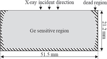
Figure 2. Sensitive and insensitive (dead) regions of the Ge crystal used for numerical simulation.
Download figure:
Standard image High-resolution imagee. Evaluation of and


The mean restricted mass electronic stopping power ratios of graphite to dry air  were calculated by numerical simulations for each x-ray quality using fluence spectra obtained by the unfolding method. Using equation (4), the
  was obtained by the fluence of electrons through the cavity. The fluence was obtained from the total range of electrons in the cavity produced in the wall material by x-ray irradiation. For electron fluence, a vacuum was used as a cavity material in the simulation to the extend range of electron slowdowns by the real cavity air. Departure from the condition of the Spencer-Attix cavity theory such as a contribution to
  from the electron interactions with the cavity air is corrected by
  The
The  was calculated by the following equation (Borg et al
2000):
was calculated by the following equation (Borg et al
2000):
where  is air kerma rates in each x-ray quality calculated from the measured photon fluence spectra, and
  is depositon energy rate in the cavity air calculated in the simulation. The
  was simply determined by the following equation:
3. Results and discussion
a. X-ray qualities and fluence spectra
The x-ray qualities of the Narrow-series, which is one of the groups defined in ISO 4037-1 (2019), were used for the calibration of the energy dependance of the dosemeter and characterized by mean energy ( ), spectral resolution (
 ), first and second half-value layers (HVLs), and homogeneity coefficient (
 ). The x-ray fluence spectra of the Narrow- series obtained from the unfolding method are shown in figure 3, and the characteristics of the NMIJ's x-ray fields are listed in table 4. Additional filters of new qualities above N-300 at the NMIJ were adjusted based on the HVL values written in ISO 4037–1. The HVL value of N-450, which was not provided in ISO 4037–1, was determined by the linear extrapolation of the effective energy, depending on the tube voltage.
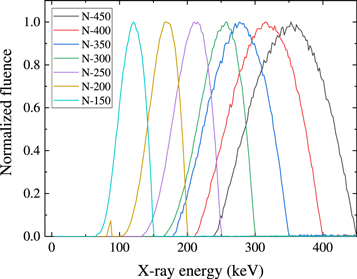
Figure 3. Fluence spectra of x-ray qualities at the NMIJ classified by ISO 4037–1 Narrow-series.
Download figure:
Standard image High-resolution imageTable 4. Characteristics of radiation qualities at the NMIJ, which contain mean energy ( ), spectral resolution (
 ), first and second half-value layers (HVLs), and homogeneity coefficient (
 ).
).
| Quality | Filtration (mm) |
 (keV) (keV) |
 (%) (%) | 1st HVL (mm Cu) | 2nd HVL (mm Cu) |

| |||
|---|---|---|---|---|---|---|---|---|---|
| Al | Cu | Sn | Pb | ||||||
| N-150 | 4 | 0.5 | 2.2 | — | 117 | 38 | 2.39 | 2.52 | 0.950 |
| N-200 | 4 | 2.0 | 2.0 | 1.0 | 164 | 31 | 4.05 | 4.17 | 0.972 |
| N-250 | 4 | — | 1.2 | 2.5 | 205 | 31 | 5.27 | 5.32 | 0.989 |
| N-300 | 4 | — | 0.5 | 4.5 | 247 | 30 | 6.21 | 6.27 | 0.991 |
| N-350 | 4 | — | 2.0 | 4.0 | 273 | 37 | 6.68 | 6.69 | 0.999 |
| N-400 | 4 | — | 2.5 | 5.8 | 313 | 37 | 7.31 | 7.36 | 0.992 |
| N-450 | 4 | — | 5.0 | 7.0 | 350 | 38 | 7.80 | 7.87 | 0.992 |
We compared measurements using the free-air chamber and the graphite-walled cavity ionization chamber from N-150 to N-250. It is difficult for the graphite-walled cavity ionization chamber to measure the air kerma below N-150, which has a significant fluence portion below 100 keV since the difference between the mass energy absorption coefficients of graphite and dry air below 100 keV exceeds several percentages, and the deviation of these ratios is large due to the x-ray energy.
b. Comparison of measurements using two types of air kerma primary standards
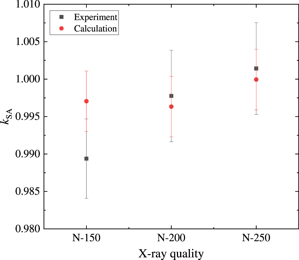
Correction factors and quantities for air kerma measurement using the cylindrical graphite-walled cavity ionization chamber in each x-ray quality were estimated by performing numerical simulations using fluence spectra, and the obtained values are listed in table 5. The values were calclated with the methods shown in the sections 2.3 and 2.5. The vlues of u mean combined uncertainties which contain both of type A and type B uncetainties. Statistical (type A) uncertainties estimated by numerical simulation is low (below 0.1%) since each history number was enough large (∼1010). As the type B uncertainties, systematic uncetainty of numerical simulation and variations in the fluence spectrum or excitation enegy were considerd. Furthermore, values of the experimental Spencer-Attix correction factor ( ) were obtained by comparing measurements using the two chambers to verify the calculation values.
The measurements in each quality were performed with the maximum tube current of 15 mA and at a distance of 3.0 m from the x-ray source. The experimental and calculated  values are shown in figure 4. The vertical errors of the experimental data show combined standard uncertainties (k = 1) from 0.54% to 0.62%. However, they do not include uncertainties of common correction factors and quantities, such as that of the
  value. As shown in figure 4, the calculation values of N-200 and N-250 agreed well with the experimental values within these uncertainties, unlike that of N-150. A possible explanation for the result of N-150 might be that the variation of the
  is very large below 100 keV and the fluence distribution of N-150 contains a significant portion in the energy range. Therefore, the calculated values of N-200 and above are available for air kerma measurements using the graphite-walled cavity chamber because the problem encountered in N-150 has less influence on the high energy side.
Table 5. Correction factors and quantities for air kerma measurement at a distance of 3.0 m by the cylindrical graphite cavity ionization chamber calculated from x-ray fluence spectra in each quality of ISO-4037–1 narrow series.
| N-150 | N-200 | N-250 | N-300 | N-350 | N-400 | N-450 | u (%, k = 1) | |
|---|---|---|---|---|---|---|---|---|

| 1.0420 | 1.0108 | 1.0065 | 1.0045 | 1.0036 | 1.0025 | 1.0017 | 0.1 |

| 1.0039 | 1.0048 | 1.0055 | 1.0057 | 1.0056 | 1.0053 | 1.0050 | 0.3 |

| 0.9998 | 0.9996 | 0.9995 | 0.9994 | 0.9994 | 0.9992 | 0.9991 | 0.06 |

| 1.0047 | 1.0094 | 1.0128 | 1.0171 | 1.0183 | 1.0213 | 1.0242 | 0.2 |

| 0.9979 | 0.9799 | 0.9814 | 0.9823 | 0.9829 | 0.9832 | 0.9832 | 0.2 |

| 0.9983 | 0.9989 | 0.9992 | 0.9994 | 0.9995 | 0.9995 | 0.9996 | 0.14 |

| 0.9971 | 0.9963 | 0.9994 | 0.9987 | 0.9966 | 0.9957 | 0.9988 | 0.4 |

| 0.9959 | 0.9823 | 0.9905 | 0.9951 | 0.9949 | 0.9972 | 1.0033 | 0.51 |

| 0.579 | 0.600 | 0.587 | 0.573 | 0.570 | 0.530 | 0.591 | 1.0 |
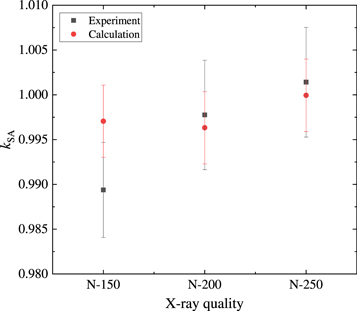
Figure 4. Comparison between the calculated and experimental values of the correction for departure from the condition of the Spencer-Attix cavity theory.
Download figure:
Standard image High-resolution imagec. Calibration of a transfer chamber
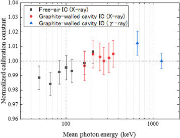
For validation of air kerma absolute measurements in new x-ray qualities such as N-350, N-400, and N-450, a spherical cavity ionization chamber, Exradin A5, with a 3-mm wall thickness was calibrated as a transfer chamber using two reference chambers. The transfer chamber was thick enough for Co-60 gamma rays to sufficiently approach the secondary charged particle equilibrium. The calibration coefficient ( ) for the transfer chamber in terms of air kerma rate (
 ) is given by
where  is the ionization current measured by the transfer chamber. The calibration coefficients depending on these effective energies are shown in figure 5. The vertical line shows the value of the calibration coefficient normalized for the Co-60 gamma ray. Error bars in each plot are relative standard uncertainties (k = 1). All measurements were performed in comparable air kerma rates in the range 0.52–0.61 μGy s−1 at a distance of 3.0 m from the x-ray source. As shown in figure 5, calibration coefficients by the new x-ray qualities are between those of medium-hard x-rays below N-300 and gamma rays and show no unexpected behavior. Therefore, the validity of the air kerma absolute measurements method using the graphite-walled cavity ionization chamber in qualities from N-200 to N-450 was confirmed.
Figure 5. Calibration results of Exradin A5 from medium-hard x-ray to gamma ray energy ranges using the free-air ionization chamber and the graphite-walled cylindrical cavity ionization chamber.
Download figure:
Standard image High-resolution image
4. Conclusion
Air kerma absolute measurement by a graphite-walled cavity ionization chamber requires determination of the mean restricted mass electronic stopping power ratio of air and a correction of departure from ideal condition of Spencer-Attix cavity theory. The validation for N-150 to N-250 were evaluated by performing measurements using different air kerma standards and numerical simulations. The calculated  values of N-200 and N-250 agreed well with their experimental values within the 0.74% combined uncertainties. The same calculation method of the stopping power ratio and the correction factor was applied to the NMIJ's new x-ray reference fields with a tube voltage of up to 450 kV. The calibration results of the transfer chamber in the new reference fields were appropriate compared with the values of the free-air chamber region and gamma-ray region. The NMIJ will conduct comparisons with the PTB or NIM for further validation of new qualities above N-300.
Data availability statement
All data that support the findings of this study are included within the article (and any supplementary files).