
Abstract
Silicone rubber (SR) composites filled with silicone rubber particles (SRP) and functionalized h-BN platelets were successfully prepared, which have high thermal conductivities and flexibility. The functionalization of h-BN adopts the combination of non-covalent and covalent modification. The Non-covalent functionalization of poly(dopamine) (PDA), which is deposited on the surface of h-BN platelets, improves the interfacial adhesion for grafting (3-aminopropyl) triethoxy-silan (KH550) by covalent modification (BN-PDA-KH550). To construct the thermal conductive pathway, silicone rubber particles are added. so that the fillers can distribute along the particle circumference by volume exclusion, which is advantageous for improving heat conduction of SR composites. The as-prepared 30 vol% BN-PDA-KH550@silicone rubber particles/silicone rubber composites (m-BN@SRP/SR) exhibited a relatively high thermal conductivity (2.24 W m−1·K−1), which is about 112 times of pure SR (0.20 W m−1·K−1). Besides, the m-BN@SRP/SR composites possessed satisfactory softness and excellent dielectric properties, which presented a broad application prospect in the field of electronic packaging.
Export citation and abstract BibTeX RIS

Original content from this work may be used under the terms of the Creative Commons Attribution 4.0 licence. Any further distribution of this work must maintain attribution to the author(s) and the title of the work, journal citation and DOI.
1. Introduction
Miniaturization, high integration, and functionalization are the development direction of electronic devices. The reason for the development is that the boost in power density of electronic components leads to a sharp increase in thermal accumulation, which is harmful to the reliability and stability of modern electronic devices [1–3]. How to enhance the thermal conductivity (TC) of polymer materials has received more attention for addressing the thermal dissipation issue [4]. Silicone rubber (SR) has been used in the electronic packaging field due to its high softness elasticity, electrical insulation, lightweight, and easy processing features. However, the low intrinsic TC of SR (only around 0.20 W m−1·k−1) becomes the major barrier for industrial application. The incorporation of thermally conductive fillers for instance BN [5], CNTs [6], Al2O3 [7], ZnO [8], and AlN [9] is the most common approach for manufacturing conventional thermal management materials. In the case of random distribution of filler, the high filler content is required to establish complete thermal transfer pathways, which inevitably leads to seriously harmful mechanical performance [10], as well as results in high interfacial thermal resistance in the filler and matrix interface [11]. Therefore, there is an urgent need to propose a novel method to construct an effective filler distribution to decline the thermal resistance.
Hexagonal boron nitride (h-BN) is a white layered crystal with a structure similar to graphite. It is characterized by high TC [12], outstanding thermal stability [13], extreme electrical insulating [14], and low dielectric constant [15]. Therefore, h-BN is considered to be an ideal filler for the manufacture of thermally conductive polymer-matrix composite materials for electronic packaging materials. General, the surface modification of the filler is a necessary procedure to decrease interface thermal resistance [16]. There have been many reports on covalent modification of BN platelets to improve interface interaction. Tang et al modify h-BN platelets via silane coupling agent (KH560) to enhance the TC and ameliorate the mechanical properties of BN/epoxy composites [17]. Ryu et al use sodium hydroxide (NaOH) to prepared functional-BN and incorporate functional-BN into polyphthalamide (PPA) to achieve higher TC [18]. Huang et al synthesized a thermally conductive epoxy nanocomposite by polyhedral oligosilsesquioxane (POSS) functionalized BNNTs [19]. Nevertheless, those covalent modification methods are complex and inefficient owing to the lack of active groups on the edge of h-BN platelets.
PDA has recently been used for non-covalent functionalization to improve the performance of polymer composites [20]. Meanwhile, it also has the potential for secondary reactions. Cai et al synthesized SnO2 nanoparticles with the assistance of polypodamine and strengthened the interfacial interaction in BN/epoxy composites [21]. Ni et al used dopamine to modified BN platelets to access natural rubber with high TC (0.46 W/(m · K)) [22]. Therefore, we have proposed the improved method basing on a combination of covalent and non-covalent functionalization.
Except for the interfacial thermal resistance, a continuous thermal conductive network is another critical element to influence the TC of composites [23]. Well contacted of fillers, and good compatibility between filler and matrix will significantly reduce the phonon scatterings and thus increase the thermal conductivity. Li et al manufacture a 3D interconnected rGO@Al2O3 hybrid fillers network in NR composites via a novel GO-assisted gelation method [24]. Guo et al report 2D nanofillers of rGO and BNNS into a micro-sandwich structure in polyimide composites [25]. Furthermore, high filler loading leads to mechanical properties deterioration, therefore filler arrangement structure is highlighted, such as segregated structure which enables TC enhancement and flexibility.
In this work, PDA wrapped on the BN platelets firstly (denoted as BN-PDA) and further grafted with KH550 containing amino functional groups (denoted as BN-PDA-KH550). As a result, the BN-PDA-KH550 platelets could structure interfacial interactions with rubber via taking part in the vulcanization reaction. Then, the as-prepared BN-PDA-KH550 platelets were controlled to distribute along the SR particle circumference by shear force during the mechanical mixing process. The method was efficient, simple, and can provide a novel general approach for the design of advanced polymer-based thermal management materials, and provides a broad application prospect for electronic packaging.
2. Materials and methods
2.1. Materials
3-Aminopropyltriethoxysilane (KH550) was purchased from Macklin. SR was purchased from Hoshino Silicon(Luzhou) Industry Co., Ltd, China. The h-BN powder (purity >99.5%, approximately 15 μm) was obtained by Dandong Rijin Science and Technology Co., Ltd, China. 2,5-Bis(tert-butyl peroxy)-2,5-dimethyl hexane (DMDBH), Tris-(hydroxymethyl)aminomethane (Tris), and Dopamine hydrochloride were provided by Aladdin Regent, China.
2.2. Surface modification of BN by dopamine and KH550
The preparation of BN-PDA-KH550 platelets was carried out according to the following procedures. Firstly, 5 g of BN platelets were immersed in a mixture of 300 ml of tris-buffer solution (10 mM, pH 8.5) and 100 ml of ethanol with sonication for 3 h at room temperature to make BN evenly dispersed. Then 600 mg of dopamine hydrochloride was put into the above-blended solution, and the mixture was vigorously stirred at 60 °C for another 24 h till the mixture's color turned gray. Subsequently, 450 mg of KH550 was added to the mixture under continuous stirring at 60 °C for 8h. After the reaction, the modified BN platelets, denoted as m-BN platelets, were centrifuged and washed several times with deionized water and ethanol until the centrifugate became colorless. Lastly, the m-BN platelets were dried in a vacuum oven at 60 0the m-B h. The color of the m-BN platelets changed from white to dark-brown, manifesting that the polydopamine was successfully coated on the BN platelets.
2.3. Preparation of SR particles by mechanical pulverizing
Firstly, pure SR composites were prepared through melt mixing by a torque rheometer. SR and DMDBH (vulcanizing agent) were mixed at 100 rpm for 10 min. The mixtures were hot-pressed in a metal mold at 160 °C under 10 MPa via a flat vulcanizing machine for further processing. Then the whole rubber lump was immersed in a liquid nitrogen tank and keep it for 3 min to ensure that has been beneath the glass transition temperature. Finally, the rubber lumps were pulverized via the high-speed pulverizing machine. Repeat the above steps until the rubber lumps were crushed to less than 300 μm. The SR particles with a size ranging from 100 to 250 μm, were named SR particles.
2.4. Preparation of m-BN@SRP/SR composites with segregated network
The m-BN platelets from 0 to 30 vol% volume fractions were mixed with SR particle, SR, and DMDBH by a torque rheometer. And SR and SRP have a mass ratio of 2:8. Then, m-BN@SRP/SR composites with a thickness of 2 mm were fabricated through hot pressing at 160 °C, 10 MPa for 20 min BN/SR composites with the same loading of filler were manufactured in the same procedure for comparison. The schematic diagram of the manufacturing procedure of m-BN@SRP/SR composites is shown in figure 1.
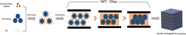
Figure 1. Schematic diagram of m-BN@SRP/SR composite manufacturing.
Download figure:
Standard image High-resolution image2.5. Characterization
An ESCALAB 250Xi (Thermo-VG Scientific, UK) X-ray photoelectron spectroscopy (XPS) system was used to analyze the surface elements of fillers. An X-ray diffractometer (XRD, Smart lab, Rigaku, Japan) was used to analyze the orientation degree of the filler. The morphology was investigated by scanning electron microscopy (SEM, Geminis 500, Zeiss, Germany). The morphology of fillers was observed via JEM-2100 (JEOL, Japan) transmission electron microscopy (TEM). The TC of the samples was tested by Hot Disk instruments (TPS 2200, AB Corporation, Sweden) and the result was average value from three repeated measurements. The thermal gravimetric analysis (TGA, Q5000IR, TA, USA) was carried out from 0 to 700 °C at a heating rate of 10 °C min−1. The infrared thermograph (FOTRIC 227s, China) was used to photograph the temperature variation. The hardness of the samples was tested by Rubber Shore Durometer (D2479-01, China) and the result was the average value from three repeated measurements. The tensile test was measured by using a universal tensile tester (CMT4204, China) according to the ASTM D412 standard.
3. Results and discussions
3.1. The BN –PDA –KH550 platelets structure and composition
The schematic diagram and mechanism of BN-PDA-KH550 platelets are demonstrated in figure 2. In general, due to the chemical inertness of h-BN, it is difficult to directly modification with KH550. Herein, we took a method including two steps reactions to modify the h-BN. The first procedure is to form a thin cover, which could be used as a versatile platform on an inert surface via self-polymerization of dopamine reaction [26, 27]. The reaction of KH550 with the hydroxyl groups of dopamine and indole, which has been grafted with PDA, is the second one [28]. Ultimately, the epoxide-dopamine was successfully prepared and self-polymerized on the surface of modified h-BN platelets.
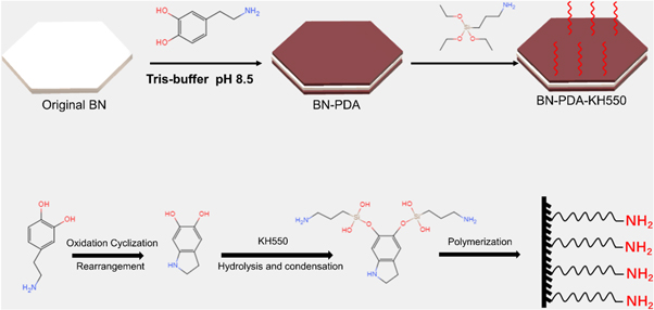
Figure 2. Schematic diagram and the reaction mechanism of BN-PDA-KH550 platelets synthesis.
Download figure:
Standard image High-resolution imageThe changes in surface elemental compositions of the three types of BN platelets were probed by X-ray photoelectron spectroscopy (XPS) and the results are reflected in figure 3. The evident peaks at 101 eV, 152 eV, 284 eV, 400 eV, and 532 eV are ascribed to Si 2p, Si 2s, C 1s, N 1s, O 1s, respectively. Comparison of figure 3(a) and (b) manifested that variation in the intensity of C 1s and O 1s peaks stemmed from the deposition of PDA on BN platelets surface. Furthermore, the C 1s spectrum of BN platelets can be decomposed into three peaks at 284.6 eV, 285.5 eV, and 286.6 eV, which can be ascribed to C–C, C–N, and C–O species. The spontaneous oxidative polymerization of dopamine caused an additional peak at 288.5 eV, which corresponds to the O–C=O species in the C1s XPS spectrum of BN-PDA platelets. As shown in figures 3(b) and (c), two new peaks of Si 2p and Si 2 s appeared at the binding energy near 101 and 152 eV, and enhanced the percentage content of O–C=O species indicated that KH550 has been grafted successfully on the cover of BN-PDA platelets.
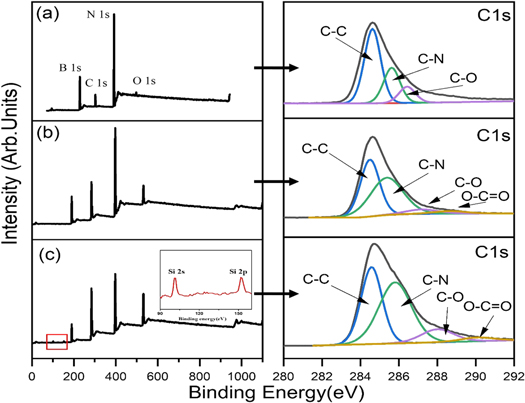
Figure 3. (a) BN, (b) BN-PDA, and BN-PDA-KH550 platelets of XPS scan and high-resolution C 1s spectra.
Download figure:
Standard image High-resolution imageXRD patterns were used to further detect the phase compositions of three kinds of BN platelets and figure 4(a) demonstrates the XRD curves. The sharp peaks of BN in the XRD pattern about at 26.9°, 41.6°, 43.9°, 50.2°, and 55.1° are attributed to the (002), (100), (101), (102), and (004) crystallographic planes of BN platelets, respectively, according to the PDA#09-0012 found in the MDI Jade database. It can be seen that there still exists characteristic diffraction peaks of BN after dopamine and KH550 modify BN platelets. Comparing with the unmodified BN platelets, the intensity of modified BN platelets' diffraction peaks becomes weaker in turn, which may be due to PDA deposition and grafting of KH550, The crystal structure still remained after being modified twice, indicating that the PDA and PDA-KH550 layers were amorphous. Moreover, TGA was used to evaluate the grafting contents of PDA and KH550 and the curves are recorded in figure 4(b). The mass residues of BN, BN-PDA, and BN-PDA-KH550 platelets were 99.6%, 97.9%, and 94.2% at 700 °C, respectively, indicating the successful grafting of PDA and KH550. And it can be calculated that the PDA modification efficiency is 1.7% and the grafting efficiency of KH550 is 3.7%.
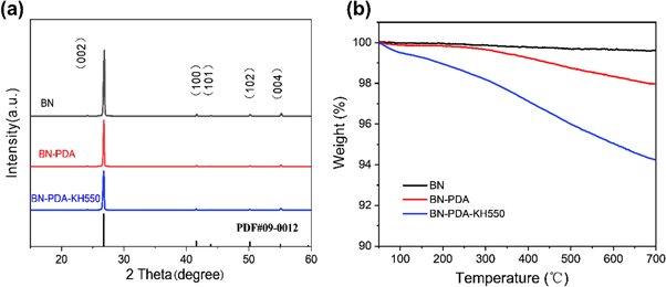
Figure 4. (a) XRD pattern and (b) TGA curves of BN, BN-PDA, and BN-PDA-KH550 platelets.
Download figure:
Standard image High-resolution imageThe surface morphologies of the BN, BN-PDA, BN-PDA-KH550 platelets were investigated by TEM. The surface of pristine BN platelets is smooth and free of impurities (figure 5(a)). Compared with figure 5(a), a continuous amorphous layer with a thickness of 10 nm has been deposited on the BN-PDA platelets surface (figure 5(b)), indicating that PDA was self-polymerized at the surface of BN platelets successfully. In figure 5(c), the thickness of the layer increased to 12 nm after grafting with KH550, demonstrating the successful grafting of KH550 with PDA. The thickness of the cover layer is taken from TEM images of several different platelets in the same sample, and the results are averaged.
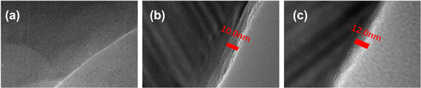
Figure 5. (a) BN, (b) BN-PDA, and (c) BN-PDA-KH550 platelets TEM images.
Download figure:
Standard image High-resolution image3.2. Morphologies of modified m-BN@SRP/SR and BN/SR composites
The arrangement of fillers in the SR matrix fundamentally determines the thermal conductivity property of the SR composite. Thence the cross-sectional morphology features of samples and the arrangement of fillers in the rubber matrix were investigated by SEM. The results were depicted in figure 6. As shown in figures 6(a)–(c), BN platelets were almost uniformly dispersed in the matrix at low filler content (5 vol%), but BN platelets gradually connected to form thermal networks in the horizontal direction along with the loading of filler increased. It's quite different from BN/NR composite, m-BN platelets tended to be attached to the surface of SR particles after the hot pressing process, forming the thermal conductive pathway. SR particles were completely wrapped by m-BN platelets at 20 vol% filler content, constructing a more perfect 3D thermal conductive network (figure 6(f)). This may owe to the good compatibility between m-BN platelets and the SR matrix.
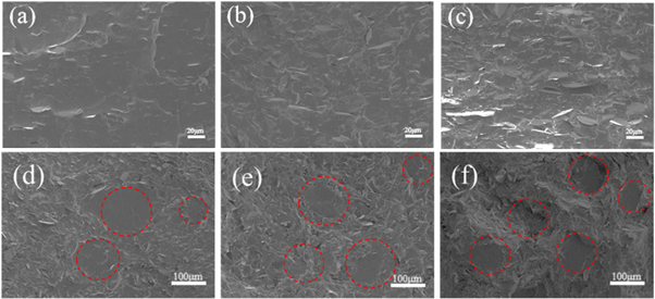
Figure 6. SEM images of (a) 5 vol%, (b) 15 vol%, (c) 20 vol% BN/NR composites, (d) 5 vol%, (e) 15 vol%, and (f) 20 vol% m-BN@SRP/SR composites.
Download figure:
Standard image High-resolution imageEDS images were used to further explore the arrangement of fillers in the SR matrix. As shown in figures 7(a) and (b), as for BN/SR samples, BN platelets were homogeneously distributed in the SR matrix. By contrast, in the case of m-BN@SRP/SR samples, m-BN platelets assembled on the surface of SR particles. The results further emphasized the incorporation of SR particles greatly improved the formation of the thermally conductive path.
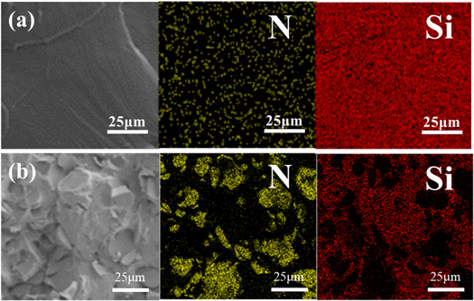
Figure 7. EDS mapping images of (a) BN/NR composites, (b) the m-BN@SRP/SR composites both at15 vol%.
Download figure:
Standard image High-resolution image3.3. Characterization of orientation degree
To research the influence of incorporated BN on the semi-crystalline structure of m-BN@SRP/SR composites, 5 vol% and 15 vol% m-BN@SRP/SR and BN/SR composites were surveyed through XRD (figure 8) [29]. The m-BN@SRP/SR composites exhibited two distinct characteristic diffraction peaks at 26.9° and 41.6°, which were ascribed to the (002) and (100) lattice plane diffraction of h-BN indicating that there was no phase change on SR composites regardless of the addition of BN. I (002)/I (100), which is the ratio of the intensity of (002) peak and (100) peak, means the degree of orientation. Compared to the I (002)/I (100) of BN/SR composites with different filler contents, it can be clearly shown that the degree of orientation increased with the increase of content. This is primarily because BN contacted with each other at higher filler loading and easy to form orientation along the in-plane direction. The same regularity also can be found for m-BN@SRP/SR with different filler concentrations. Taking the I (002)/I (100) of both m-BN@SRP/SR and BN/SR composites at the same concentration for comparison, it can be found that the orientation degree of BN in m-BN@SRP/SR is less than that in BN/SR. The degree of anisotropy is significantly weakened due to the effect of rubber particles, m-BN@SRP/SR sample is mainly reflected in the isotropic state. The reason for this phenomenon is that BN selectively distributed at the surface of SR particles rather than disorderly distributed in the SR matrix. It indicated that fillers could easier re-orient under the hot pressing especially when a large sum of BN is located in the gap of SR particles. More importantly, it proves that the thermal conductive pathway was indeed successfully constructed in the m-BN@SRP/SR composites.
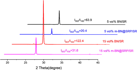
Figure 8. XRD results of 5 vol% and 15 vol% m-BN@SRP/SR and BN/SR composites.
Download figure:
Standard image High-resolution image3.4. Thermal conductivity and mechanical properties
To further clarify the degree of improvement, a parameter η was introduced, which is defined as

Where Kc and Km mean the TC of the rubber composite and pure SR, respectively. The difference of η was small at low volume fraction because the thermal conductive network was not completely structured. Figure 9(a) presents the effect of the content of m-BN or BN fillers on the TC of composites. The m-BN@SRP/SR composites possess relatively higher TC than that of BN/SR composites at the same content of fillers. With the filler content increased, the difference became larger. When the content of fillers reaches 30 vol%, the difference is at its maximum, and the corresponding TC value of the m-BN@SRP/SR and BN/SR composites were enhanced to 2.25 and 1.26 W/(m·K) respectively, which are higher than TC of pure SR (0.20 W/(m·K)). Meantime, thermal conductivity enhancement(TCE) of the m-BN@SRP/SR sample was up to 1023% at the maximum content of 30 vol% (figure 9(b)), which was more than twice the BN/SR sample. The first reason for the difference is that enhanced interfacial interactions between m-BN platelets and SR matrix declined interfacial thermal resistances, which in turn significantly improving TC. Second, the directional distribution of m-BN platelets is advantageous for constructing effective thermal transfer networks.
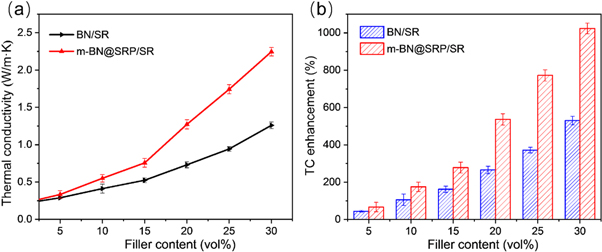
Figure 9. (a) TC of BN/SR samples, m-BN@SRP/SR samples; (b) thermal conductivity enhancement of two kinds of the sample.
Download figure:
Standard image High-resolution imageTherefore, the study found the modified BN wrapped SR particle promotes the perfection of the thermal conductivity network, so the TC is better; the unmodified BN promotes the poor performance of that network formation, which affects the improvement of the TC. Table 1 illustrates a comparison of TC of the m-BN@SRP/SR composites with the reported polymeric composites.
Table 1. Comparison of the TC of different filler and polymeric composites.
| Matrix | Filler | Loading | TC(W m−1 · k−1) | TCE(%) | Year |
|---|---|---|---|---|---|
| NR | PDA-BN | 30 vol% | 0.46 | 460 | 2019 [22] |
| NR | Al2O3 | 18 vol% | 0.514 | 514 | 2020 [24] |
| SR | Al2O3 | 55 vol% | 1.53 | 665 | 2020 [30] |
| PMMA | FCNT | 15 wt% | 0.96 | 405 | 2019 [31] |
| MVSR | MCFs@SiO2 | 20 vol% | 0.409 | 109.7 | 2018 [32] |
| SR | PDA-KH550-BN | 30 vol% | 2.24 | 1023 | This work |
Through making a tangent to the curve, find the volume fraction of the point that makes the temperature change the most. There is an intersection point of the two tangent lines which can be concluded from figures 10(a) (b), the point corresponding to the percolation threshold of composites (VC). According to figure 10(b), the VC of m-BN@SRP/SR was 13.6, which implies that the basic thermally conductive network has been constructed in this volume fraction. By comparing figures (a) and (b), the Vc value of the m-BN@SRP/SR sample was less than that of the BN/SR sample, indicating that SR particles help to speed up the formation of a thermally conductive network. The results further emphasized that the dispersion state of fillers and the perfect thermally conductive network within the SR matrix are two key points for the enhancement of BN/SR composites.
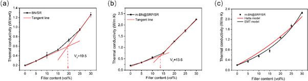
Figure 10. (a) (b) The tangent for the original experimental data and obtained the value of Vc; (c) fitting TC results of m-BN@SRP/SR composites by EMT model and Hatta model.
Download figure:
Standard image High-resolution imageThe physical model including effective medium theory (EMT) [33, 34], Hatta model [35], and Foygel's theory [36] was used to calculate the interfacial thermal resistance (Rc1) between fillers and SR matrix and Rc2 of the filler-filler interface, respectively.
The Hatta model, the equation is as follow:

Where Kfiller and Km are TC of filler platelets and SR matrix respectively; V is the volume fraction of filler; S is a coefficient related to the direction of the thermal conductivity test.
The EMT model, the equations are as follows:

With


Where Kfiller and Km are TC of filler and SR matrix respectively; Vf is the filler volume fraction, L and d are the lateral size (15 μm) and thickness (0.2 μm) of BN.
Hatta model and EMT model were used to fit experimental TC (figure 10(c)). R-squared is an important indicator of goodness of fit. By comparing R-squared to find a more suitable fitting model, the data is shown in table 2. It can be seen from figure 10(c) and table 2, the Hatta model and EMT model could match with the experimental data well both, but the EMT model has a slightly higher degree of fit and better matches the experimental data. Therefore, the interfacial thermal resistance(Rc1) was quantitatively calculated by the EMT model. According to the above equation (3)–(4), Rc1 of m-BN@SRP/SR and BN/SR composites is 2.71 × 10⁻⁷ m2 KW−1 and 4.26 × 10⁻⁷ m2 KW−1 respectively, which means that PDA-KH550 modified BN can decrease the interface thermal resistance between BN platelets and SR matrix.
Table 2. Comparison of R-squared values of EMT model and Hatta model.
| R-squared | EMT model | Hatta model |
|---|---|---|
| BN/SR | 0.9993 | 0.9863 |
| m-BN@SRP/SR | 0.9930 | 0.9816 |
The interface resistance of filler- filler Rc2 should be calculated by Foygel's model, which is shown as followed:

Where K0 is the coefficient related to BN; β is an index that depends on the aspect ratio of filler; K is the TC of the rubber composites; Vf is the volume fracture of filler; Vc is the percolation threshold, which can be received from figures 10(a) (b);
the Rc2 can be calculated by the following equation:


Where


According to the equations above (5)–(8), Rc2 of m-BN@SRP/SR and BN/SR composites is 3.2 × 10⁻⁶ m2 KW−1 and 4.4 × 10⁻⁶ m2 KW−1, suggesting that the interfacial thermal resistance between the BN platelets and BN platelets was decreased by modifying the BN with PDA-KH550.
The phonon transmission models of m-BN@SRP/SR and BN/SR composites are schematically described in figure 11, which clearly illustrate the different interfacial thermal conduction mechanisms. For BN/SR composites, since BN is randomly dispersed in the polymer matrix, heat flow is transferred between the BN platelets and the polymer matrix. The thermal boundary resistance induced by the polymer layer between the fillers causes phonons to scatter, thereby this leads to a short phonon free path. Therefore, the heat transfer efficiency of BN/SR composites is fairly low. With the incorporation of SR particle, the fillers were well aligned within the gap of particle and closely touched with each other structuring a perfect heat transfer path. When heat flow is preferentially transferred between m-BN platelets, it will produce a longer phonon mean free path and higher thermal transfer efficiency [37]. Phonons scatter less in the process of transferring heat, so the TC increases more obviously.
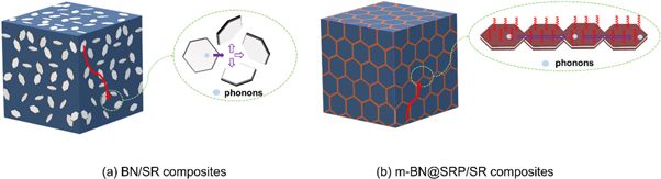
Figure 11. The illustration of the phonon transmission models (a) BN/SR composites (b) m-BN@SRP/SR composites.
Download figure:
Standard image High-resolution imageThe increase in TC generally comes at the cost of a significant reduction in mechanical properties. But m-BN@SRP/SR composites, which keep relatively low hardness, were obtained through improved methods. The hardness curves of BN/SR and m-BN @ SRP/SP composites were presented in figure 12, the effect of filler volume fraction on the hardness of SR composites is almost linear, which is the same as the TC increases along with the improvement of the filler volume fraction. The reason for this phenomenon may be that the fillers of BN/SR composites are scattered in the matrix randomly, so they cannot be in full contact. When the SR composite is deformed by an external force, the obstruction from the fillers is small. But for m-BN@SRP/SR composites, more factors are affecting. On the one hand, the fillers between SR particles in the segregated structure system are denser, and the hindering effect on the movement of rubber molecules is greater. On the other hand, the incorporated SR particles still keep good flexibility. Thus the hindrance is relatively small when subjected to an external force.
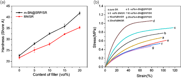
Figure 12. (a) The hardness curves and (b) Stress-strain curves of BN/SR and m-BN@SRP/SR composites with different loading of filler.
Download figure:
Standard image High-resolution imageThe results of the tensile test are consistent with that of the hardness curve. For m-BN@SRP/SR composites, more BN platelets were located around SRP to form filler channels. Comparing with BN/SR composites, it will decrease the relative concentration of the rubber within BN platelets. This means that the mechanical properties have dropped to a certain extent, and the ultimate tensile strength is reduced by 9.0% compared with pure rubber. However, the breaking stretch rate of a series of m-BN@SRP/SR composites was still above 80%, which is acceptable for rubber pads used in electronic packaging. All in all, these results indicate that the rubber composite still maintains its flexibility despite the excessive addition of BN.
To demonstrate the heat dissipation ability of m-BN@SRP/SR composite, a commercial LED was placed on a series of samples as the heat source (figure 13(a)), which imitates the working state of the electronic device, was used to observe surface temperature during the hot process [38]. The thermography and temperature change of LED were monitored and recorded every 10 s by an infrared thermal imager. As shown in figure 13(b), m-BN@SRP/SR composite constructed an effective thermal conductive channel that accelerated the heat dissipation of LED light efficiently. After the heating process of 120 s, the surface temperature of the LED placed on the m-BN@SRP/SR composite is about 58 °C, which is significantly lower than the surface temperature of pure SR (71.3 °C). Moreover, the pure SR composites had a faster rate of temperature increase in the same working time, while the m-BN@SRP/SR sample showed the slowest rate of temperature change. It should be noted that the decrease in the temperature of LED is due to heat transfer from LED to SR. Thus composites with high TC performance a fast heat dissipation rate. Figure 13(c) showed that samples with high thermal conductivity turned to darker color slower due to the optimized heat conduction network, hence the m-BN@SRP/SR can dissipate the accumulated heat in time. All results above manifested that m-BN@SRP/SR composites could be potentially applied as thermally conductive rubber pads.
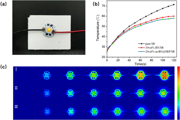
Figure 13. (a) The photograph of LED light placed on the sample; (b) temperature curves of pure SR and composites with 20 vol% filler content; (c) infrared thermal images of different samples (I pure SR; II 20 vol% BN/SR; III 20 vol% m-BN@SRP/SR).
Download figure:
Standard image High-resolution image3.5. Thermal stability analysis
The thermal stability properties of m-BN@SRP/SR composite were characterized by thermo-gravimetric analysis, as shown in figure 14. By adding m-BN platelets, the initial decomposition temperature of m-BN@SRP/SR composite revealed an upward trend, as shown in table 3. The temperatures T5% and T50% (decomposition temperature at 5% and 50% weight loss) were used to evaluate the thermal stability of materials. With the loading of m-BN increases, both T5% and T50% raised monotonously. When filler content was 20 vol%, T5% and T50% of the m-BN@SRP/SR composites reached 472.6 °C and 673.3 °C respectively (table 3) which were about 29.1 °C and 158.4 °C higher than that of the pure SR. The result indicated that the thermal stability of the SR composites was remarkably improved compared with the neat SR after the incorporation of m-BN platelets and SR particles.
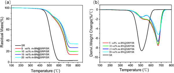
Figure 14. (a) TGA and (b) DTA belong to the m-BN@SRP/SR along with increased m-BN loading.
Download figure:
Standard image High-resolution imageTable 3. T5%, T50%, and Residual mass of m-BN@SRP/SR composites with different filler content.
| Samples | T5%(%m | T50%(0% | Residual mass |
|---|---|---|---|
| SR | 443.5 | 514.9 | 3.2% |
| 5% m-BN@SRP/SR | 467.0 | 646.0 | 14.0% |
| 10% m-BN@SRP/SR | 468.0 | 652.2 | 19.9% |
| 15% m-BN@SRP/SR | 471.4 | 664.2 | 26.8% |
| 20% m-BN@SRP/SR | 472.6 | 673.3 | 33.9% |
There are two thermal decomposition processes for m-BN@SRP/SR composite which can be seen from DTG curves in figure 14(b), one peak located at about 502 °C and the other peak is located at 671 °C. Due to the perfect heat conductive pathway in m-BN@SRP/SR composite, the heat flow can rapidly be conducted. Hence, the silicon rubber that coated on BN (within the heat conductive skeleton) will decompose first to form a dense char layer. This is the first decomposition process. The char layer insulates the heat from further transferring to the rubber particles inside, so the rubber particles inside will decompose at much higher temperatures. The shielding effect of filler also remarkably delayed the escape of rubber degradation products. Therefore, the temperature of the maximum decomposition rate is increased from 502 °C to 671 °C.
3.6. Dielectric properties
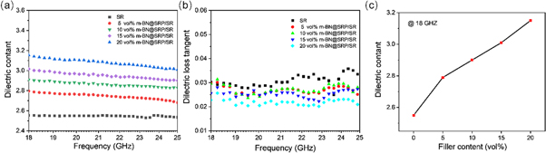
Figure 15 depicted the dielectric constant and dielectric loss tangent curves of pure SR and m-BN@SRP/SR composites, which were measured in the frequency range from 18 to 25 GHz. The dielectric constant of m-BN@SRP/SR composites appeared a slight rise along with the increase of filler content, which is due to Maxwell-Wagner polarization at the interface between the BN and rubber matrix. For the 20 vol% m-BN@SRP/SR composite material, the maximum dielectric constant was 3.15 at 18 GHz, which is larger than the dielectric constant of pure SR (2.56 at 18 GHz), but still at a lower level. Also, the dielectric constant of the m-BN@SRP/SR composites presented a downtrend with the increase of frequency, which may be because the polarization of the material could not catch up with the frequency vary at high frequency, so the dielectric constant continues to decrease.
Figure 15. (a) Dielectric constant and (b) dielectric loss tangent as a function of frequency for pure SR and m-BN@SRP/SR composites. (c) Dielectric constant at 18 GHz
Download figure:
Standard image High-resolution image
According to figure 15(c), it is found that the dielectric loss tangent of m-BN@SRP/SR composites was lower than that of the pure SR. The dielectric loss tangent decreases with the increasing content of m-BN platelets. This phenomenon can be explained by the following two reasons. First, the significant contribution of the inherent features of BN inhibits the charge migration. Secondly, the dispersion of filler in the SR matrix was improved by modification and directional alignment, thus there were fewer flaws and pores in the m-BN@SRP/SR composites which could be the dominant contribution. The great dielectric properties of the m-BN@SRP/SR composites provide an effective guarantee for the long-term operation of the microelectronic device.
4. Conclusions
In this work, h-BN was successfully functionalized by a feasible method including the deposition of PDA and graft of KH550. The results of XPS, TEM, TGA, and XRD tests together confirmed the functional modification of BN-PDA-KH550. The 3D filler networks were successfully constructed by surface modification of BN and volume exclusion of SR particles. The EDS mapping further confirmed that m-BN selectively distributes along the particle circumference. Compared with BN/SR composites, the m-BN@SRP/SR composites presented a higher TC of 2.24 W m−1·K−1 in 30 vol% filler content, and the low dielectric constant (3.15) and dielectric loss tangent (0.02) in 18 GHz. Meanwhile, it still maintains a low hardness with a relatively large filling volume. The m-BN@SRP/SR composites with high TC, excellent dielectric properties, and good mechanical properties provide a new strategy to construct an efficient thermal network and promises potential applications as electronic packaging materials in electronic devices.
Acknowledgments
The author would like to acknowledge the financial support from the National Key R&D Program of China (No. 2017YFB0406200).
Data availability statement
The data that support the findings of this study are available upon reasonable request from the authors.
Compliance with ethical standards
Conflict of interest
The authors declare that they have no conflicts of interest.