

Abstract
Due to its low melting point and high hardness, Ni60 (Ni–Cr–B–Si) alloy is widely used as surface cladding material for mould steel. In present study, Ni60 alloy thin-walled samples were fabricated using laser metal deposition (LMD) technology on H13 steel substrate which is usually used as mould material. The microstructure and mechanical properties (microhardness and wear resistance) of LMD Ni60 alloy were investigated. The results show that the LMD Ni60 alloy sample is mainly composed of Ni, Ni3Fe, Ni3B, Ni3Si, CrB, Cr5B3 and Cr7C3. The microstructures of the sample mainly include Ni–B–Si eutectics, Ni columnar dendrites and precipitates (boride and carbide). In the region with faster cooling rate of the sample, eutectics take a larger proportion, meanwhile precipitates are refined and dispersed uniformly. So hardness of the region can reach 950 HV. In the interlayer region, eutectics decrease while Ni dendrites increase because of the influence of remelting. The hardness of this region is about 750 HV. Wear resistance tests indicated that the wear resistance of LMD Ni60 alloy is about 9 times of H13 steel.
Export citation and abstract BibTeX RIS

Original content from this work may be used under the terms of the Creative Commons Attribution 4.0 licence. Any further distribution of this work must maintain attribution to the author(s) and the title of the work, journal citation and DOI.
1. Introduction
Ni60 (Ni–Cr–B–Si) alloy is a well-known hard-facing alloy with excellent wear resistance, corrosion resistance, low melting point and self-fluxing property [1]. With its unique performances, Ni60 alloy is widely applied for surface coating, mould repairing and mould producing by spraying, fusing and laser cladding techniques [2, 3]. Recently, LMD technique has been applied in producing and repairing of complex components, the use of which is not limited by the complexity of components [4].
Previous works on LMD mainly focused on steel, Ni-based super alloy, Ti-6Al-4V, and Al alloy [5–7]. There are only a few investigations on additive manufacturing of Ni–Cr–B–Si hard-facing alloys. Abe et al made high strength metallic components by selective laser melting (SLM) method. They found that moulds can be formed using Ni–Cr–B–Si alloy, but defects were observed [8]. Kozo Osakada et al fabricated Ni–Cr–B–Si alloy moulds by SLM, and the finite element simulation was used to optimize process to avoid defects [9]. Andrea Angelastro et al investigated direct laser metal deposition (DLMD) of Ni–Cr–B–Si alloy (Colmonoy-227). They studied the effects of process parameters such as hatch space, step height, laser power, scanning speed, specific energy and powder flow rate on the quality of DMLD components, and a mathematical model was used to obtain the optimum parameters [10–12]. Paul et al fabricated Ni–Cr–B–Si alloy (Colmonoy-6) bushes without defects by laser rapid manufacturing (LRM), and the quality of LRM components compared well with these fabricated using tungsten arc welding (GTAW) [13]. Hemmati et al investigated the microstructure and phase formation of laser cladded Ni–Cr–B–Si–C hard-facing alloy. They found that Ni–Cr–B–Si coatings consisted of different kinds of Cr boride, Cr carbide, dendrites of Ni solid solution and Ni–B–Si eutectics, and the microstructure depend on alloy compositions and processing parameters [14–16]. In summary, these works on additive manufacturing of Ni–Cr–B–Si alloys have mainly focused on the optimization of process parameters, but the research on microstructure and properties of LMD Ni–Cr–B–Si alloys is not mature [17].
In the present work, LMD technique was used to fabricate Ni60 alloy multi-layer thin-walled components on H13 steel substrate which is usually used as mould material. This study focused on the microstructure, phase constitution and phase formation in different regions of the LMD Ni60 alloy component. Mechanical properties such as hardness and wear resistance were also studied. The correlation between microstructure and hardness was discussed in detail.
2. Experimental materials and methods
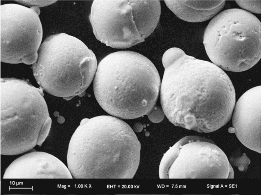
The LMD equipment consists of a semiconductor laser device (maximum laser power is 1000 W), powder feed system and IRB1410-ABB robot controlled by computer. Figure 1 shows the scheme of LMD process. Ni60 alloy powder used in this study was produced by gas atomization. The particle size varied from 53 to 150 μm as shown in figure 2. Table 1 shows the composition of Ni60 powder. Ni60 alloy was deposited as thin-wall samples on H13 steel plates as shown in figure 3. In order to study the microstructure and avoid cracks, optimized parameters were used, as shown in table 2.
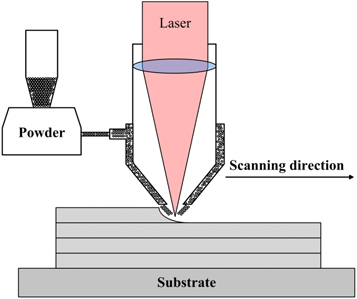
Figure 1. Scheme of LMD system.
Download figure:
Standard image High-resolution image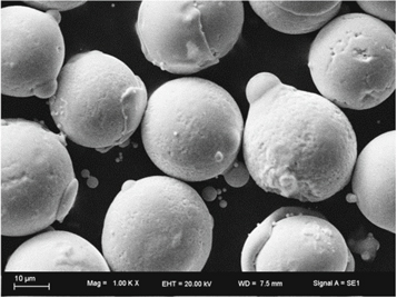
Figure 2. SEM image of Ni60 powder.
Download figure:
Standard image High-resolution imageTable 1. Compositions of Ni60 alloy powder (wt/%).
| Ni | Cr | B | Si | Fe | C |
|---|---|---|---|---|---|
| Bal. | 16.00 | 3.20 | 4.00 | 15.00 | 0.80 |
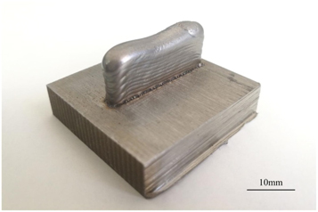
Figure 3. Appearance of LMD Ni60 sample.
Download figure:
Standard image High-resolution imageTable 2. Parameters of LMD.
| Laser power/W | Scan speed/mm · s−1 | Spot diameter mm−1 | Powder feed rate/g · min−1 | Z increment/mm |
|---|---|---|---|---|
| 400 | 5 | 1.25 | 7.3 | 0.6 |
Ni60 powder was fed into the melt pool through a coaxial nozzle. Argon acted as the powder carrier and shielding gas to prevent the melt pool from oxidation. Metallographic specimens were etched with a mixture solution consisted of 20 ml HNO3, 20 ml CH3−COOH and 30ml HCl. Microstructure of samples were investigated by optical microscopy (OM) (Zeiss Axio Imager A1m) and scanning electron microscopy (SEM) (TESCAN VEGA3) equipped energy-dispersive spectroscopy (EDS). X-ray diffraction (XRD) (Rigaku D/Max 2500PC) was used to analyze phase constitution of samples. The hardness of samples was measured using MH-3 Vickers hardness tester with 500g load and 10s load time. Wear resistance of samples was tested using ML-100 abrasion tester in comparison with H13 tool steel substrate.
3. Results and discussion
3.1. XRD analysis
Phase constitution of the LMD sample is complicated because of the rapid heating and cooling process. According to previous studies, microstructure constitution of Ni–Cr–B–Si alloy mainly includes Ni dendrites, boride and carbide precipitates as well as binary and ternary Ni–B–Si eutectics [16]. The XRD analysis of the phases was carried out by using a Rigaku D/Max 2500PC system based on the 2θ method and the results are shown in figure 4. The data was processed by using MDI Jade (version 6.5) software and the major phases in the sample specimen were identified as Ni, Ni3Fe, CrB, Cr5B3, Ni3B, Ni3Si and Cr7C3, corresponding to the relevant diffraction peaks as labled in figure 4. In laser formed Ni–Cr–B–Si alloy, CrB, Cr5B3 and Cr7C3 are typical hard phases. Ni exists in Ni dendrites, meanwhile Ni3Fe, Ni3B and Ni3Si exist in eutectics [15].
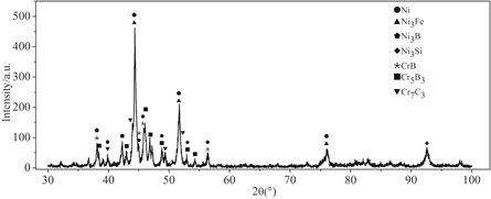
Figure 4. XRD pattern of LMD Ni60 alloy.
Download figure:
Standard image High-resolution image3.2. Microstructure observation
Figure 5(a) is the OM image of cross section of the sample. The LMD sample is a multilayer stack of laser deposited tracks. According to the difference of microstructure, the sample can be divided into three regions (I, II , III) as indicated in figure 5(a). Microstructures in different regions are presented from figures 5(a)–(e). Region I is the center of deposited layer. Region II is the remelting area between two layers. Because of the remelting of the base layer, microstructure of region II is significantly different from region I. Region III is close to surface of the sample. The temperature gradient in this region is larger and the cooling rate is faster than region I and II .
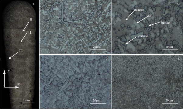
Figure 5. OM image of Ni60 alloy sample in cross section (a); low-magnification OM image of region I (b); high-magnification OM image of region I (c); low-magnification OM image of region II (d); low magnification OM image of region III (e).
Download figure:
Standard image High-resolution image3.2.1. Microstructure of Region I
Figure 5(b) shows that the microstructure consists of precipitates, dendrites and eutectics in the region I. Different shape and size of precipitates can be observed. Figure 5(c) shows that there are two kinds of blocky precipitates. Gray blocky precipitates are bigger and more distributed than the white ones. Some of the white precipitates have dendritic structure. Figure 6 presents the SEM and EDS analysis of the region I. It shows that the dendrites in figure 5(b) are Ni dendrites. Ni, B and Si distribute uniformly in eutectics. Light colored precipitates are Cr carbides because of the concentration of Cr and C. Deep colored precipitates are Cr borides because of the concentration of Cr and B. Based on the XRD analysis, the microstructures of region I consist of Ni dendrites, Ni-B-Si eutectics and precipitates (CrB, Cr5B3, Cr7C3 ).
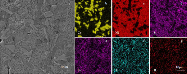
Figure 6. SEM(a) and EDS images of region I Cr(b); Ni(c); Si(d); Fe(e); C(f); B(g).
Download figure:
Standard image High-resolution image3.2.2. Microstructure of Region II
Region II is the interlayer region. The width of this region is about 60–80 μm as shown in figure 5(d). Due to the laser remelting, the microstructure in this region is significantly different from the region I and III. Compared with the region I, the proportion of dendrites and precipitates in the region II is larger, and the proportion of eutectics is smaller. In addition to the blocky precipitates, some precipitates are dendritic which distribute radially around the block Cr borides as shown in figures 5(c)–(d). Figure 7 is the result of SEM and EDS analysis of the region II , and it can be concluded that the dendritic precipitates are Cr7C3 combined with XRD analysis.
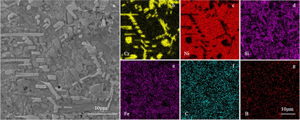
Figure 7. SEM(a) and EDS images of region II Cr (b); Ni (c); Si (d); Fe (e); C (f); B (g).
Download figure:
Standard image High-resolution image3.2.3. Microstructure of Region III
Figure 8 shows the results of SEM and EDS analysis of region III. Because of the higher cooling rate, the size of precipitates in region III is smaller than region Iand II . Compared with other two regions, Ni dendrites in this region are less and eutectics are more.
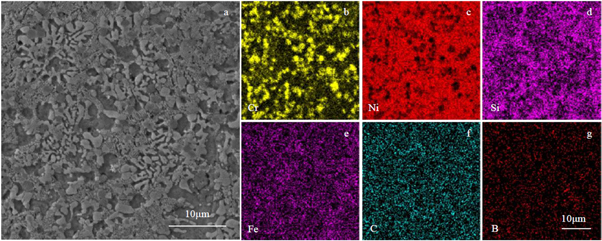
Figure 8. SEM(a) and EDS images of region III Cr (b); Ni (c); Si (d); Fe (e); C (f); B (g).
Download figure:
Standard image High-resolution image3.3. Mechanism of microstructure formation
XRD analysis shows that the phase formation of the LMD Ni60 alloy is complicated. During the LMD process, different cooling rates lead to different solidification morphology [16]. According to Cr–B, Cr–C, Ni–B, Ni–Fe phase diagram [18], temperatures of phase reactions that may occur during LMD process are as follows:
In the solidification process of region I, Cr borides and carbides form at first. Next, as the temperature goes down, dendrites of Ni appears. At last, Ni–Cr–B eutectics fill the space between precipitates and dendrites. In Region II , a large number of precipitates and Ni dendrites appear due to partly remelting of the fore deposited layer. When the fore deposited layer is partly remelted, temperature rise and eutectics melt. But the temperature is not high enough to melt Ni dendrites. When it begins to solidify, Ni dendrites grow up and the proportion of Ni dendrites significantly increases. Because the increase of dendrites consumes a lot of Ni, eutectics decrease compared to region I. The decrease of eutectics led to the enrichment of B element which is in favor of the formation of Cr precipitates.
Region III is close to the edge of the sample as shown in figure 5, so the cooling rate is very fast. The large temperature gradient promotes the precipitates nucleation and restrains the growth of Ni dendrites. During the solidification process, growth of precipitates was very limited. When the temperature decreases to the eutectic temperature, there are more Si and B element left in the melt which causes the increase of eutectics.
Due to the high cooling rate, typical floret-shaped structure forms in the LMD Ni60 alloy. According to the existing research, this kind of structure is the product of the non-equilibrium eutectic reaction at about 1100 °C which is composed of layered Ni and Cr5B3 [14]. As shown in figures 5(c) and (d), Cr7C3 dendrites grow radially around the Cr borides. According to the Cr–C and Cr–B phase diagrams, formation temperature of Cr7C3 is lower than Cr borides. Therefore, during the solidification process, Cr borides are firstly precipitated, and then Cr carbides nucleate attaching to first precipitate borides. With the growth of Cr carbides, radial structure forms at last [16].
3.4. Hardness and wear resistance
The hardness test was conducted along the X and Y directions on the cross section of sample as shown in figures 9 and 10. The average hardness of region I and region II is about 850 HV and 800 HV, respectively. The average hardness of region III is the highest which is about 900 HV.
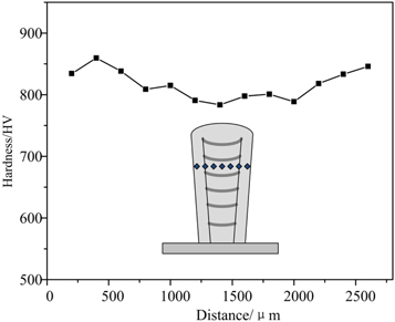
Figure 9. Microhardness distribution of sample along X direction.
Download figure:
Standard image High-resolution image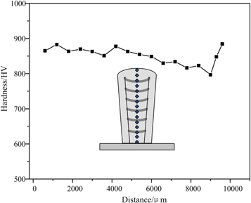
Figure 10. Microhardness distribution of sample along Y direction.
Download figure:
Standard image High-resolution imageAmong the phases of the Ni60 alloy, the hardness of Ni dendrites is 280–365 HV. The hardness of Cr carbides is 1080–1450 HV. The hardness of Cr borides and Ni borides can reach 1500–2400 HV [19]. Therefore, the distribution of the eutectics and the precipitates determines the hardness of LMD Ni60 alloy. Figure 9 shows the hardness distribution on the cross section of sample along the X direction. It is obvious that the hardness on both edges of the sample is higher than the middle. This is because the cooling rate on both edges of the sample is faster, and the precipitates such as CrB, Cr5B3 and Cr7C3 are finer and distributed uniformly, in addition to the increase of eutectics and the decrease of Ni dendrites.
Figure 10 shows the hardness distribution of the sample along the Y direction. The lower hardness appears at the remelting region, because of the decrease of the eutectics as well as the increase of precipitates and Ni dendrites. As indicated in figure 10, the hardness distribution in the range of 0∼4000 μm is relatively stable, and the hardness in the range of 4000∼9000 μm begins to decrease, but it increases again near the top of the sample. This is because in the first few LMD layers, the sample is mainly cooled by the substrate where the cooling rate is faster. With the increase of layers, the cooling condition of the melt pool becomes worse and worse, and the cooling rate decreases, resulting in the decrease of the hardness. At the top layers, the hardness rises again. Because at the final stage of the process, the melt pool is easier to dissipate heat to the surrounding environment, and the cooling rate is faster, so the hardness increases.
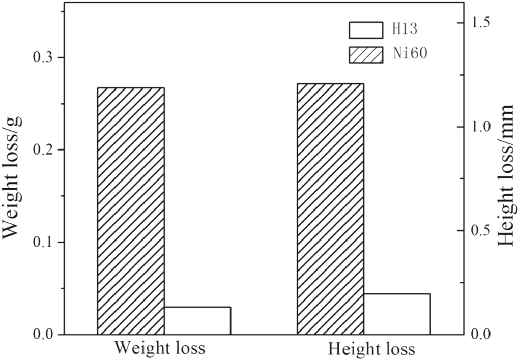
The wear resistance of the LMD Ni60 alloy was studied by comparing the H13 steel substrate which is usually used as mould material. Results are shown in figure 11. Under the same wear test conditions, the weight loss and height loss of the LMD Ni60 alloy specimens were 0.0296 g and 0.196 mm respectively. The weight loss and height loss of the H13 steel were 0.2673 g and 1.207 mm respectively. The wear resistance of the LMD Ni60 alloy sample is about 9 times of the H13 steel. Figure 12 shows the wear morphology of H13 steel and LMD Ni60 samples. The furrows on H13 steel sample were long and deep, while furrows on the Ni60 alloy sample were shallow. The wear resistance of LMD Ni60 is significantly better than that of H13 steel.

Figure 11. Wear resistance of H13 steel and Ni60 alloy.
Download figure:
Standard image High-resolution image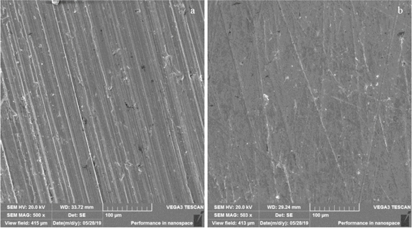
Figure 12. Wear morphology of H13 steel (a) and Ni60 alloy (b).
Download figure:
Standard image High-resolution image
4. Conclusion
- (1)The thin-walled Ni60 alloy sample was successfully fabricated by LMD technology. With the optimized process parameters, a well-formed sample with no macro cracks was obtained.
- (2)The LMD Ni60 alloy is mainly composed of Ni dendrites, Cr borides, Cr carbides and eutectics. The difference in cooling rate results in different microstructures in different regions of the sample. In the region where the cooling rate is faster, eutectics increase, meanwhile the precipitates are finer and uniformly distributed. In the interlayer regions, Ni dendrites and precipitates increase and eutectics decrease.
- (3)Refiner precipitates and larger amount of the eutectics can increase hardness of LMD Ni60 alloy. Laser remelting which causes the increase of precipitates and Ni dendrites can decrease the hardness of the LMD Ni60 alloy. The average hardness of the LMD Ni60 alloy is about 850 HV, and the wear resistance of LMD Ni60 alloy is about 9 times of the H13 steel.
Acknowledgments
This work was financially supported by the co-construction project between Jilin Province and Jilin University (440050316A14, SXGJQY2017-14) as well as Wenzhou Science and Technology Bureau through Project Grant ZG2017032.