
Abstract
Iron metal possesses good biocompatibility and excellent mechanical strength, though it degrades too slowly. In this work, selective laser melting (SLM) was applied to fabricate iron-manganese (Fe-Mn) biodegradable scaffold. Results shown Fe-Mn scaffold exhibited a uniform pore structure with a porosity of 66.72 ± 2.3%, which highly matched with as-designed model. Phase analysis revealed Fe-Mn scaffold mainly contained α-Fe, martensitic and austenitic phases. Due to the potential difference among these different phases, galvanic corrosion occurred in Fe matrix. In addition, a small amount of Mn distributed at grain boundaries also contributed to the formation of galvanic corrosion. Thus, the corrosion rate increased from 0.09 ± 0.02 mm/year to 0.23 ± 0.05 mm/year. The scaffold exhibited suitable mechanical properties with a yield strength of 137 ± 8.4 MPa, an ultimate strength of 221.7 ± 10.9 MPa. Moreover, cell assays demonstrated its good cytocompatibility. Taking these positive results into consideration, SLM processed Fe-Mn scaffold was a promising material for bone repair application.
Export citation and abstract BibTeX RIS

Original content from this work may be used under the terms of the Creative Commons Attribution 3.0 licence. Any further distribution of this work must maintain attribution to the author(s) and the title of the work, journal citation and DOI.
1. Introduction
As one of the three elements of bone tissue engineering, artificial bone scaffold plays an extremely important role in bone repair process [1, 2]. Ideally, scaffolds should have high porosities with open pore structure, over which cells can rapidly grow and develop into tissues that are viable [3, 4]. Meanwhile, they usually require a customized shape that matches the defect site, so as to reduce excessive bone resection during transplantation. Nevertheless, fabricating such bone scaffolds with a complex internal structure and a personalized shape poses a huge challenge to traditional manufacturing technology, such as casting, powder metallurgy, machining and so on.
Additive manufacturing (AM) technology has currently gained intensive attention for fabricating synthetic bone scaffolds as orthopedics implants [5–9]. Unlike the conventional material removal processes, AM involves a whole host of 'bottom up' approaches, which creates three dimensional objects originated from computer-designed models by gradually building them up with a layer-by-layer method [10, 11]. Such a high level of process flexibility enable it can directly fabricate complex internal structures and customized shapes. Up to now, AM has been applied to prepare bone scaffolds from various materials, including metals [12–14], polymers [15–17] and ceramics [18–20], even their composites [21–23]. Among them, metal bone scaffolds are most promising for load-bearing bone repair [24].
Biodegradable metals, mainly including Fe, Zn and Mg, have attracted the attention of researchers in recent years [25–28]. This is because they not only provide good mechanical structural support, but also gradually degrades in the body, which perfectly realizes the clinical application of the bone implant as a temporary substitute. Fe degrades more slowly but has superior mechanical strength than Mg and Zn, exhibiting greater potential as synthetic bone scaffold material [29]. Previously, Fe had been studied as a biodegradable scaffold, and induced no obvious inflammatory response or systemic toxicity during a long term period [3]. Besides, some researchers reported that alloying with manganese (Mn) could adjust the degradation of Fe [30]. More significantly, Mn is an essential trace element for human body [31].
To the best of our knowledge, although, alloying with Mn for enhancing the degradation rate of Fe had been studied by some researchers, there were few papers reporting on AM of Fe-Mn scaffold. In this study, selective laser melting (SLM), as one of AM techniques, was applied to prepare Fe-Mn scaffold. SLM was characterized by using high laser energy to fully melt thin metal powder layer [32–34]. The corrosion behavior, mechanical properties and biocompatibility of SLM processed Fe-Mn scaffold was investigated systematically, with an aim to assay its potential for bone repair applications.
2. Materials and methods
2.1. Materials and samples preparation
A self-developed SLM system consisted of a fiber laser, a powder delivery system and a computer control system was used as the samples manufacturing equipment. Spherical Fe powder (∼45 μm) and spherical Mn powder with size ranging from 5 to 10 μm were used as the starting material. Fe power and Mn powder (25 wt%) were mixed by utilizing a ball mill for 2 h at a speed of 260 rpm. The determination of the Mn addition was based on previous studies [30]. The obtained Fe-Mn mixed powder was used in SLM experiments. After several preliminary experiments, Fe and Fe-25Mn scaffolds were prepared with optimized parameters: laser power 120 W, scanning speed 3 m s−1, layer thickness 0.1 mm, spot size 0.05 mm and scanning distance 0.04 mm. During SLM, the new powder was spread by roller mechanism on the former layer, and the laser selectively melting the layer according to the cross section of as-designed model until the whole part was complete. These experiments were performed in an argon atmosphere with a purity of 99.9%.
2.2. Microstructural characterization
The samples were firstly mechanically polished with SiC papers up to 2000 grit and ultrasonically cleaned in ethanol. Subsequently, the samples were etched in a 4 vol.% nitric acid alcohol solution for 10 s. The microstructure was investigated using an optical microscope (OM, Leica DM4700, Germany). Meanwhile, the microstructure was investigated using a scanning electron microscope (SEM, QUANTA FEG250, FEI Company, USA) in backscatter mode at 20 kV. The chemical composition was investigated by an energy dispersive spectroscopy (EDS, JSM-5910LV, Japan). The phase composition was determined utilizing an x-ray diffractometer (XRD, D8 Advance, Bruker AXS Inc., Germany) with a scanning rate of 8 °/min.
A micro-computed tomography (μCT) scanner (FF35 CT; YXLON International, Germany) was used to scan the scaffold. Two dimensional slice images were collected, as the scaffolds were rotated by steps of 0.36° up to 360°. Then the three dimensional model was reconstructed through the obtained slice images using a software named VGStudio MAX 3.0. The porosity was subsequently analyzed from the reconstructed models by using software named Magics (Version 21.0.0, Materialise, Belgium).
2.3. Compression tests
According to the standard of ISO 13314: 2011, the compression tests were carried out using an electronic universal testing machine (CMT5105, MTS System Corporation, USA). The scaffold with a height of 16 mm was used in compression tests, with a loading of 100 kN and a pressure head speed of 2.5 mm min−1. Each group was repeated five times for the averages.
2.4. Electrochemical tests
Electrochemical tests were used to analysis the electrochemical behavior of SLM prepared Fe and Fe-25Mn. Before the tests, cubic sample (6 × 6 × 6 mm3) was linked with a copper wire and inserted in epoxy resin. Then an exposed surface with an area of 0.36 cm2 was polished using sandpaper, and ultrasonically cleaned using alcohol. Subsequently, the tests were performed on an electrochemical workstation (CHI604D, CH Instruments, Shanghai, China). The platinum, Ag/AgCl and the samples served as counter electrode, reference electrode and working electrode, respectively. Simulated Body Fluid (SBF) was used as the test solution. The detailed composition of SBF could be seen in reference [35]. After obtaining the open circuit potential (OCP), the potentiodynamic polarization curves were adopted within a potential window of OCP ± 200 mV. During electrochemical impedance spectroscopy (EIS) test, the frequency ranged from 0.01 Hz to 100 kHz, and the signal amplitude was 10 mV. Besides, the surface after electrochemical test was further investigated using SEM and EDS.
2.5. Immersion experiments
Immersion tests were carried out in SBF at pH of 7.4 and temperature of 37 ℃ according to ASTM-G31-72 [36]. During the immersion, the ion concentrations of Fe and Mn in SBF solution were detected using an inductively coupled plasma-atomic emission spectroscopy (ICP-AES, Thermo Elemental, USA). After immersion for one month, the scaffold was taken out from SBF. Then the corrosion products were washed out using chromic acid. The corrosion rates were obtained after measuring the weight loss (W) [37]:

Where C was the corrosion rate, D was the standard density, A the exposure area and t was the soaking time.
2.6. Cell test
In indirect cell assay, the scaffold was firstly immersed in dulbecco's modified eagle medium (DMEM) for 3 days to obtain 100% concentration extract. The ratio between exposure area and solution volume was set at 1.25 cm2·ml−1. 50% extract was obtained by diluting the 100% extract by pure DMEM. MG-63 cells (5 × 10⁴ cells mL−1) were seeded in a 96-well with 100 μl of DMEM and incubated for 1 day. Then cells were cultured in 100% and 50% extract for 1, 3 and 5 days at 37 ℃. Subsequently, CCK-8 solution (10 μl) was added in the each well and incubated for another 2 h. Then the absorbance was obtained utilizing a paradigm detection platform (BECK MAN, CA) at 450 nm.
In direct cell assay, MG-63 cells (1 × 10⁵ cells per well) were directly seeded on the scaffold in 24-well plates. After culture for 1, 3 days, the cells were gently washed using phosphate buffered solution (PBS) and stained for 15 min with calcein-AM and ethidium homodimer-1 solution. In detail, calcein-AM stained live cells in green, and ethidium homodimer-1 stained dead cells in red. All the stained cells were gently washed using PBS for two times. Then the cells morphologies were observed using a fluorescence microscopy (BX60, Olympus, Japan). Besides, the cells culture for 5 days on scaffold were directly observed using SEM, after the cells were fixed in 2.5% glutaraldehyde solution for 2 h.
2.7. Statistical analysis
The data were analyzed using SPSS 19.0 software. Student's t-tests were carried out to define the difference, which was believed to be significant as p < 0.05.
3. Results
3.1. Morphology and microstructure
The as-designed model and as-built Fe-Mn scaffold were presented in figure 1(a). The morphology of the as-built scaffold observed by SEM was shown in figure 1(b), which revealed that the scaffold exhibited a uniform pore structure. The two dimensional section from the as-built scaffold obtained by μCT was presented in figure 1(c). The strut thickness, volume and porosity of as-built Fe-25Mn scaffold were obtained by μCT analysis. Results shown that Fe-25Mn scaffold exhibited a strut thickness of 600–800 μm, porosity of 66.72 ± 2.3%, volume of 98.63 ± 5.4 mm3, which were very close to those of as-designed model. These results indicated that the scaffold prepared by SLM possessed high dimensional accuracy.
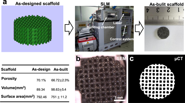
Figure 1. (a) The as-designed model, home-made SLM equipment and as-built scaffold; (b) The SEM showing the structure of as-built scaffold; (c) The two dimensional section from as-built Fe-Mn scaffold obtained by μCT. The inset table listed the macro structural characteristics obtained by μCT analysis of as-built Fe-Mn scaffold.
Download figure:
Standard image High-resolution imageThe microstructure of SLM processed Fe-25Mn and Fe scaffolds were shown in figure 2. In general, no obvious pores and cracks were observed in the matrix, indicating that SLM process was capable of fabricating part with high densification level. Furthermore, uniform equiaxed grains were observed for Fe-25Mn and Fe scaffolds (figures 2(a) and (b)). Obviously, Fe-25Mn scaffold exhibited a reduced grain size as compared with Fe scaffold. Meanwhile, some Mn-contained phased distributed at grain boundaries (figure 2(a)). The microstructure feature of Fe-25Mn scaffold was further investigated utilizing SEM combined with EDS (figure 2(c)). Mn mainly dissolved in Fe matrix (figure 2(c2)). EDS results indicated that 19.2 wt% (Point 2) and 20.3 wt% (Point 3) of Mn dissolved in Fe matrix, forming high Mn solid solution.
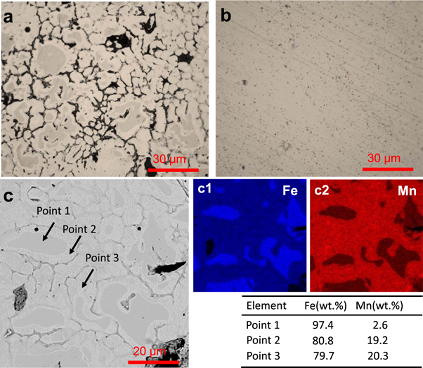
Figure 2. The OM images of (a) Fe-25Mn and (b) Fe; (c) SEM of Fe-25Mn scaffold, and corresponding EDS map which exhibited the distribution of Fe and Mn.
Download figure:
Standard image High-resolution imageTypical XRD spectra of SLM-processed Fe and Fe-25Mn scaffolds were depicted in figure 3(a). Clearly, SLM processed Fe scaffold mainly consisted of α-Fe phase, whereas SLM processed Fe-25Mn scaffold contained α-Fe, martensitic phase (JCPDS 44–1290) and austenitic phase (JCPDS 33–397). As alloyed with Mn, Fe and Mn atoms homogenously arranged and formed a solid solution with a face-centered cubic (fcc) crystal structure, which was known as austenitic phase [38].
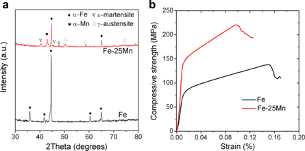
Figure 3. (a) XRD spectrum of SLM processed Fe and Fe-25Mn scaffolds; (b) Typical stress-strain curves derived from compressive experiments.
Download figure:
Standard image High-resolution imageCompressive tests were performed to study the mechanical behavior of Fe and Fe-25Mn scaffolds, with characteristic stress-strain curves depicted in figure 3(b). In detail, the obtained stress-strain curves started with a linear elastic region, and continued with a plateau region with fluctuating stresses, which presented the same trend as other typical porous scaffolds. The corresponding compressive properties derived from these stress-strain curves were shown in table 1. Due to the porous structure with high porosity, Fe scaffold only exhibited a yielding strength of 70.3 ± 4.2 MPa, an ultimate strength of 135 ± 5.2 MPa. As a comparison, Fe-25Mn scaffold exhibited improved compressive properties with yield strength of 137 ± 8.4 MPa and ultimate strength of 221.7 ± 10.9 MPa. These results indicated that alloying with Mn significantly enhanced the compressive properties.
Table 1. The compressive properties of SLM derived scaffolds.
| Scaffolds | Yield strength (MPa) | Ultimate strength (MPa) | Strain |
|---|---|---|---|
| Fe | 70.3 ± 4.2 | 135 ± 5.2 | 15.2 ± 1.8% |
| Fe-25Mn | 137 ± 8.4 | 221.7 ± 10.9 | 9.3 ± 1.5% |
3.2. Corrosion behavior
Typical potentiodynamic polarization curves of SLM process Fe and Fe-25Mn were shown in figure 4(a). The electrochemical properties analyzed from the potentiodynamic polarization curves were shown in figure 4(b). Clearly, Fe had a relatively high potential of -0.61 ± 0.04 V and a small corrosion current density of 7.38 ± 3.21 μA cm−2. As for Fe-25Mn, the corrosion potential negatively shifted to -0.74 ± 0.06 V. Meanwhile, the corresponding corrosion current density increased to 51.25 ± 7.52 μA cm−2. It was well accepted that a more negative corrosion potential indicated a weakened corrosion resistance of the surface, while an enhanced corrosion current density revealed an accelerated corrosion rate. Therefore, the lower corrosion potential and enhanced corrosion current density indicated the lower stability of Fe-25Mn in SBF solution. Besides, the obtained EIS curves of Fe and Fe-25Mn exhibited similar shape (figure 4(c)), indicating their same corrosion mechanism. It should be noted that Fe-25Mn part exhibited a lower polarization resistance than Fe part.
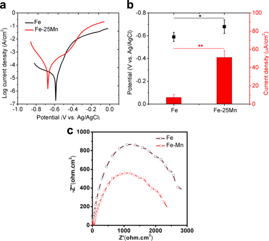
Figure 4. (a) Representative potentiodynamic polarization curves of Fe and Fe-25Mn samples in SBF; (b) the electrochemical parameters obtained from electrochemical tests; n = 3, *p < 0.05, **p < 0.01; (c) The Nyquist plots for Fe and Fe-25Mn samples.
Download figure:
Standard image High-resolution imageThe corroded surfaces of SLM derived Fe-25Mn and Fe after electrochemical tests were observed by SEM (figures 5(a) and (b)). For Fe sample, almost no corrosion products were observed, only leaving some very shallow corrosion pits, which indicated that only a slight electrochemical corrosion occurred on the surface. As a comparison, a large amount of corrosion products remained on the surface of Fe-25Mn sample, forming an extremely rough corrosion surface. Particularly, partial surface seemed to be covered by cracked layers, whereas some region covered an entire corrosion product layer. This indicated that Fe-25Mn experienced severe local corrosion during the electrochemical test. The elemental composition of corrosion products on Fe-25Mn was investigated using EDS, with results shown in figures 5(c) and (d). It could be seen that the formed corrosion products mainly consisted of O, Fe, C and Mn. It was reasonable to deduce that these corrosion products should be hydroxides and carbonates, which was in accordance with previous literature [30].

Figure 5. The SEM images showing surface morphologies of Fe-25Mn (a) and Fe (b) after electrochemical tests; The element distribution (c) and EDS spectrum (d) corresponding to figure 5(a).
Download figure:
Standard image High-resolution imageImmersion tests were performed to further study the corrosion behavior of Fe and Fe-Mn scaffolds, with results shown in figure 6(a). After considering the estimated surface area of scaffold, Fe scaffold presented a small corrosion rate of 0.09 ± 0.02 mm/year, while Fe-25Mn scaffold shown a considerably accelerated corrosion rate of 0.23 ± 0.05 mm/year. The evolution of the concentration of Fe and Mn ions in SBF during immersion was depicted in figure 6(b). Clearly, Fe-25Mn scaffold released considerably more ions than that of Fe scaffold. For the Fe scaffold, the Fe ion concentration showed slight change during the soaking period, indicating its extremely slow degradation rate. As for Fe-25Mn scaffold, both Fe and Mn ions increased sharply and reached 15.1 ± 3.3 mg L−1 and 4.9 ± 1.1 mg L−1, respectively, after immersion for 4 weeks. These results confirmed the enhanced degradation rate of Fe-25Mn scaffold as compared with Fe scaffold.
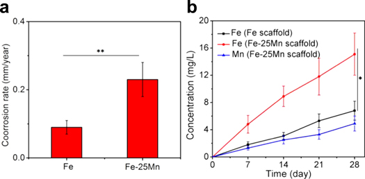
Figure 6. (a) Calculated degradation rate based on soaking experiments; (b) Fe and Mn ion concentration curves during immersion tests. n = 3, *p < 0.05, **p < 0.01.
Download figure:
Standard image High-resolution image3.3. In vitro cell response
CCK-8 assay was performed to evaluate the cytotoxicity of SLM processed Fe and Fe-25Mn scaffolds, with results shown in figure 7(a). After cultured in 100% extract of Fe scaffold for 1, 3, 5 days, the MG-63 cells exhibited cell viabilities of 78.8 ± 3.5%, 84.2 ± 4.2% and 91.5 ± 5.6%, which revealed the good biocompatibility of Fe. As for Fe-25Mn scaffold extracts, the cell viabilities at 1, 3, 5 days were 68.5 ± 5.9%, 71.4 ± 5.1% and 75.2 ± 4.2%, respectively. As cells were cultured in 50% concentration extract, the obtained cell viabilities was enhanced to 78.6 ± 6.5% at day 1, and 85.4 ± 4.6% at day 3 and 92.2 ± 3.8% at day 5. These results indicated that 100% extract of Fe-25Mn scaffold shown slight cytotoxicity, while 50% extract shown no obvious cytotoxicity to MG-63 cells.

Figure 7. (a) The CCK-8 results showing the cytotoxicity of Fe-Mn and Fe scaffolds, n = 3, *p < 0.05. (b) Fluorescent images of MG-63 cells on scaffolds after incubation for 1 and 3 days. (c) SEM observations of MG-63 cells on scaffolds after incubation for 5 days. The arrows indicated the cellular extensions across the pore walls.
Download figure:
Standard image High-resolution image
The morphologies of MG-63 cells after direct culture on scaffolds for 1, 3 days were observed by fluorescence microscopy, with results shown in figure 7(b). Green represented live cells and red represented dead cells. Obviously, few dead cells were observed for both Fe and Fe-25Mn scaffolds. Most of the MG-63 cells presented classical spindle shape, indicating their normal cell growth. Furthermore, the adhered cells on scaffold clearly increased with culture period extending, which also confirmed their good biocompatibility.
The adhesion morphology of MG-63 cells on scaffolds was further investigated by SEM, with results shown in figure 7(c). It could be seen that the adhered cells after culture for 5 days shown high cell densities. Meanwhile, the MG-63 cells formed a large amount of cell-cell junctions and cytoplasmic extension, as indicated by red arrows. The formed cytoplasmic extensions bridged pore walls and even infiltrated in the pores, which indicated that a good interface bond formed between the scaffolds and cells. These results further confirmed the good biocompatibility of SLM processed Fe-25Mn scaffold.
4. Discussion
4.1. Microstructure and mechanical properties
The porous structure of the bone scaffold is of great importance for bone repair. This is because the porous structure can provide space for cell growth, facilitate normal cell activity and maintain unique functional activity, thus guiding tissue-oriented endogenous growth. Compared with conventional processing techniques, AM technologies offer significant advantages in fabricating porous bone scaffolds because of its special layer by layer process. Combined with CAD and CT technology, it can produce bone scaffolds with precise and controllable internal structure, as well as customized shape [39]. Previously, researchers had successfully employed AM techniques to fabricate porous metal scaffolds, such as Ti based scaffolds [40] and 316 L steel scaffolds [41], for bone implant application. Nevertheless, both Ti and 316 L have no degradability, thus need a second surgery to remove. Researchers had also used AM techniques to prepare polymer and ceramic scaffolds [42]. But neither polymer nor ceramic scaffolds could meet the mechanical requirements for bone repair, especially for the weight bearing bone repair.
As a metal material, Fe possesses good mechanical strength and ductility, which makes it competent to provide a structural supporting during service. Even more valuable is that it also has natural degradability. The degradation products show no toxicity to human body. Therefore, researchers have tried to prepare biodegradable Fe based bone implants for bone repair. For instance, Chou et al applied inkjet 3-D printing method to fabricate Fe-based scaffold [43]. An organic solvent was used as the binder during the printing process. Results shown that 3-D printed Fe-based scaffolds exhibited relative insufficient mechanical strength, with a yield strength of ∼106 MPa. Therefore, a secondary sintering as post-treatment was required to improve the mechanical properties (yield strength ∼239 MPa), which certainly increased the complexity of the fabricating process. Moreover, some organic solvents were inevitably left in the 3-D printed scaffolds, which might deteriorate its original good biocompatibility. Xie et al applied spark plasma sintering to prepare Fe-Mg bone implants [44]. Nevertheless, spark plasma sintering had difficulty in realizing individualized customization.
In the present study, SLM technology was proposed and used to prepare Fe-Mn scaffold as bone implants. It was considered to be an effective approach for metal AM. μCT scanning analysis revealed that the obtained scaffolds were highly matched with as-designed models, which indicated that SLM technology achieved good molding accuracy. In present study, after focusing the laser beam with a wavelength of 1.06 μm, a very small spot with a size of 50–60 μm was obtained, which was certainly beneficial to improve the processing accuracy. In addition, with the advent of high-precision galvanometers, it was capable to achieve a high-precise and high-speed scanning, which was also conducive to improve the processing accuracy and efficiency of SLM. Previous studies had confirmed that SLM was capable of preparing pore structures with a pore size of about 300–800 μm, which was on par with that of macron pore in natural bone [4].
On the other hand, SLM was based on a complete melting/solidification process. A high-power laser was employed to output a high energy, so that the metal powder melted completely under the laser radiation. In this case, a complete molten pool was obtained, which subsequently experienced the solidification and formed solid parts in a layer-by layer method. Such a complete melting/solidification process was believed to make a contribution to obtain parts with high densification rate, without the aid of post heat-treatment. As observed by SEM and OM, no obvious defects, including pores and cracks, were observed in the Fe matrix, which confirmed this point. Previous literatures also revealed that the parts fabricated by SLM could achieve extreme high densification rate over 99% [45]. Fundamentally, SLM was also a rapid solidification process accompanied with a high thermal gradient and an extremely high cooling rate. It was well accepted that a rapid solidification could interrupt the grain growth and reduce segregation [46]. Thus, fine and uniform microstructure was obtained in the matrix of Fe-25Mn part (figure 2). The obtained high densification rate, as well as fine and uniform microstructure, was beneficial to improved mechanical properties of SLM processed scaffolds. In present study, the SLM processed Fe-25Mn scaffold exhibited enough compressive strength, as compared with that of natural cortical bone (130–180 MPa) [47]. Notably, SLM derived Fe-25Mn scaffold shown high compressive strength than that of Fe scaffold. This was supposed to be closely associated with the fine grain strengthening effect and a second phase strengthening caused by the orderly dispersion of second phase. Nevertheless, the Mn-contained phase distributed along grain boundaries would cause embrittlement in Fe-Mn scaffold. Thus, its elongation accordingly decreased to a certain extent.
4.2. The degradation behavior of Fe-Mn scaffold
Proper degradation rate is of great importance for porous bone scaffolds. Too rapid a degradation rate results in a rapid loss of mechanical strength, causing a premature failure of scaffold after implantation. And too slow a degradation rate will hinder the growth of new bone tissue, thus affecting the quality of bone repair.
It is well known that the degradation of Fe is a typical electrochemical corrosion process. Thus, electrochemical tests, which were usually used to characterize the electrochemical stability, were performed to evaluate the degradation behavior of SLM processed Fe and Fe-25Mn. Results indicated that the electrochemical stability of Fe matrix decreased after alloying with Mn, which could be deduced from the obtained electrochemical parameters, including the decreased the corrosion potential and increased corrosion current, as well as reduced electrochemical impedance. Mn possesses a relative lower corrosion potential as compared with Fe. Therefore, when Mn was alloyed with Fe, the corrosion potential of Fe matrix was reduced. For Fe-Mn alloy, unstable Mn oxide would form on the surface, which had a low passivity coefficient than that of Fe oxide [48]. In this case, the surface passivity was significantly decreased, resulting in accelerated electrochemical corrosion once pitting corrosion occurred. This might explain why the corrosion current of Fe-25Mn was enhanced during electrochemical tests.
Immersion tests were performed to evaluate the long-term degradation behavior, which might provide more accurate characterizations of the degradation property. The mass loss data from the immersion tests revealed that SLM processed Fe scaffold had an average degradation rate of 0.09 ± 0.02 mm/year. It was in accordance with previously literature, which reported that the degradation rate of Fe was about ∼0.10 mm/year in SBF solution. More importantly, the immersion tests indicated that Fe-25Mn scaffold had an accelerated degradation rate of 0.23 ± 0.05 mm/year. Increased degradation rate was believed to be associated with reduced surface passivity and galvanic corrosion between multiple phases in Fe matrix. The phase composition analysis revealed that Fe-25Mn scaffold contained α-Fe, martensitic and austenitic phases. Due to the potential difference between these different phases, galvanic corrosion formed among them, thus accelerating the corrosion rate. In addition, a small amount of Mn segregated at grain boundaries (figure 2(a)), which also contributed to the formation of galvanic corrosion, with Mn corroding preferentially. Such a dissolve of Mn caused a high concentration of Mn ion in SBF solution. The corroded surface of SLM processed Fe-25Mn also confirmed its greater tendency for corrosion as compared with Fe (figure 5(c)). During the corrosion of Fe-25Mn, a large amount of Fe2+ and Mn2+ were released into the solution, and subsequently formed insoluble hydroxides which would deposited on the surface. Hydrogen depolarization would occur and form hydrogen gas, which resulted in the formation of corrosion pits in which hydrogen gas were released [49]. Thus, cracked corrosion layer was easily formed on the corroded surface.
4.3. The biocompatibility of Fe-Mn scaffold
Although alloying with Mn accelerated the degradation of Fe matrix, the release of excess Mn ions may also cause cytotoxicity. Thus, the cytocompatibility of SLM derived scaffold was investigated systematically in vitro. As MG-63 cells were cultured in 50% concentration extract of Fe-25Mn scaffold, the cell viability reached 85.4 ± 4.6% at day 3, and even 92.2 ± 3.8% at day 5, which indicated that it shown no obvious inhabitation for cell growth. Nevertheless, relative low cell viability was demonstrated in 100% concentration extract after culture for 1 and 3 days. Such a considerable reduction in cell viability was believed to be related with the too high Mn concentration in culture medium. Mn was reported to reduce the viability of MG-63 cells by 50% at a concentration of 1 × 10⁻⁴ M (5.4 mg L−1) [50]. In fact, the local ion concentration in vivo would be considerably relieved, due to the dynamic cycling environment [51, 52]. Therefore, the cells culture in 50% concentration extract or even low concentration might be more convincible to reflect the effect of Mn ions on cell growth in vivo environment.
In direct culture, a large amount of live cells with healthy morphology was observed using fluorescence microscopy after 1 day culture on Fe and Fe-25Mn scaffolds, which directly confirmed that cells grow normally on scaffolds. Meanwhile, with extending culture time to 3 days, the cell density gradually increased, indicating that more cells adhered on the scaffold. These positive results were also confirmed by the SEM observations of the adhered cells on scaffolds. And a few cells grew across and into the pores, as indicated in figure 7(c). Previous study revealed that cells preferred to fill the locations with high curvature, such as the micro-scale surface pores, ravines of struts and small pores [53]. In present study, micro scale pores and ravines was built on the strut connection sites, which provided superior appearance environment for cells proliferation and adhesion on the scaffolds. Besides, the porous structure also provided diversified mechanical stimuli for adhered cells, thus might enhance the osteoblast differentiation [54, 55]. In short, in vitro assays revealed the good cytocompatibility of SLM derived Fe-25Mn scaffold.
5. Conclusions
In this work, porous Fe-Mn scaffold was successfully fabricated by SLM technology. The obtained scaffold exhibited a uniform pore structure with high porosity, which confirmed the processing accuracy and flexibility of SLM in the preparation of metal bone implant. Mn mainly dissolved in Fe matrix and formed high Mn solid solution, including martensitic and austenitic phases, due to the rapid solidification effect obtained by SLM. Meanwhile, laser rapid solidification also caused refined and homogenized microstructure. Mechanical tests revealed that the Fe-Mn scaffold demonstrated appropriate mechanical properties for load-bearing applications. Significantly, the Fe-Mn scaffold presented a more fast and proper degradation rate, as compared with Fe scaffold. In vitro cell assays further revealed its good cytocompatibility, with cells normally grew on the scaffolds. The overall results suggested that SLM processed Fe-Mn scaffold shown great potential for bone repair application.
Acknowledgments
This study was supported by the following funds: (1) The Natural Science Foundation of China (51935014, 51905553, 81871494, 81871498, 51705540); (2) Hunan Provincial Natural Science Foundation of China (2019JJ50774, 2018JJ3671, 2019JJ50588); (3) JiangXi Provincial Natural Science Foundation of China (20192ACB20005); (4) Guangdong Province Higher Vocational Colleges & Schools Pearl River Scholar Funded Scheme (2018); (5) The Open Sharing Fund for the Large-scale Instruments and Equipments of Central South University; (6) The Project of Hunan Provincial Science and Technology Plan (2017RS3008).
Data statement
Date will be made available on request.