


Abstract
Inertial confinement fusion (ICF) is currently one of the two main paths towards an energy source based on thermonuclear fusion. A promising ICF option is ion fast ignition (IFI), in which the ignition of nuclear fuel is initiated by an intense laser-driven ion beam. This paper presents the results of systematic numerical (particle-in-cell) studies of the properties of laser-driven carbon ion beams produced under conditions relevant for IFI, and the feasibility of achieving beam parameters required for fuel ignition is discussed. It was found that a 1 ps 200 kJ infrared laser driver is capable of producing ion beams with parameters required for IFI, even with a simple non-optimised target, but only at small distances (⩽0.1 mm) from the target. At such distances, the beam intensity and fluence exceeds 5 × 10²¹ W cm−2 and 2 GJ cm−2, respectively, while the beam energy approaches 30 kJ. The ion beam parameters can be significantly improved by carefully selecting the target thickness and shape. However, even with an optimised target, achieving the beam parameters required for IFI is possible only at distances from the target below 0.5 mm. The ion acceleration is accompanied by the emission of powerful (⩾50 PW) pulses of short-wavelength synchrotron radiation which are the source of significant ion energy losses and may pose a threat to the fusion infrastructure. In addition to ICF, the extremely intense ion beams demonstrated in the paper can be a unique research tool for research in nuclear physics, high energy-density physics or materials science.
Export citation and abstract BibTeX RIS
1. Introduction
Inertial confinement fusion (ICF) and magnetic confinement fusion (MCF) are currently the two main directions of research on controlled thermonuclear fusion aimed at creating a new energy source based on the fusion reaction of light nuclei, in particular the nuclei of hydrogen isotopes: deuterium (D) and tritium (T). Unlike MCF, where the energy from the fusion reaction is produced continuously or over long periods of time, ICF produces energy in repeated short (sub-nanosecond) explosions of thermonuclear fuel (e.g. DT) concentrated in a spherical pellet and compressed to very high densities. In the conventional approach to inertial fusion [1–4], as proposed in the early 1970s [1], the pellet containing DT fuel is symmetrically illuminated by many nanosecond laser beams or x-rays generated by a laser, Z-pinch or ion beam. As a result of pellet irradiation, rapidly expanding plasma is produced on the pellet surface. The momentum of the expanding plasma is balanced by the momentum of the inner part of the pellet, which leads to the implosion of the pellet and a decrease of its volume. The decrease of the pellet volume is accompanied by an increase of the fuel density and an increase of the temperature inside the pellet. At a sufficiently high reduction in volume, the temperature in the pellet centre rises to very high values (∼10 keV) and a 'hot spot' formed in such a way allows the self-ignition of the fuel. However, the implementation of this type of fuel ignition (usually referred to as central hot spot ignition—CHSI) in real ICF systems is associated with the need to meet numerous requirements that are difficult to achieve. In particular, CHSI requires: ensuring high efficiency of energy transfer from the laser to the fuel, precise control of the fuel compression symmetry, avoiding mixing of hot and cold fuel caused by hydrodynamic instabilities, preventing overheating of compressed fuel by x-rays, hot electrons and others. To meet these requirements, the fuel pellet must be made with extremely high precision and sphericity (with aberrations of no more than a few micrometres over both inner and outer surface), short-wavelength radiation (UV laser beam or soft x-rays) must be used to compress the fuel, and the beams irradiating the pellet must be extremely precise and must arrive at the same time on the pellet. Moreover, very high laser energies (multi-MJ) are needed to achieve in this option the high energy gain necessary for the fusion reactor.
The above-mentioned extremely difficult to attain requirements for CHSI have become an inspiration to look for alternative options for fuel ignition in which at least some of these requirements would be relaxed. Among these options, the so-called shock ignition (SI) [5–8] and fast ignition (FI) [9–15] are currently considered the most promising although other options such as proton–boron fusion are also under investigation [16–19]. In SI, the role of an ignitor of the DT fuel is played by a strong, converging shock wave generated in the fusion target in the final stage of its compression by the most intense final part of an appropriately shaped laser pulse compressing the fuel. This option has been described in detail in, e.g. [7, 8]. In the FI option, the ignition of the DT fuel, initially compressed with a multi-beam laser or x-rays to ∼1000 densities of the solid DT, is the result of the rapid heating (over ∼10 ps) of a small part of the fuel by a very intense flux of particles: electrons [9–15, 20, 22], protons [21, 23–26, 75] or ions [21, 27–38]. FI has some potential advantages over CHSI, namely: a higher energy gain, reduced requirements for compression symmetry, lower overall driver energy, and flexibility in using various kinds of compression drivers (lasers, X-pinches, ion accelerators [39]). However, the downside is the need to efficiently produce and deposit in the fuel a particle beam with extreme parameters that are difficult to achieve using conventional accelerators.
One of the currently studied FI variants is the so-called ion fast ignition (IFI), in which a laser-driven beam of ions (e.g. Be, C, Al or V ions) is used to ignite the fuel. The advantage of IFI compared to the FI variant using an electron beam is a more efficient and localised deposit of ion energy to the fuel, along with the relatively well-controlled transport of ions from the ion source to the fuel. Compared with much lighter and less energetic protons, the number of accelerated ions necessary to ignite the fuel can be several orders of magnitude lower (1014 for C ions or 1013 for V ions, vs 1016 for protons [21]), meaning that the volume and transverse size of the ion source can be much smaller than the proton source. This, in turn, means that, unlike with a proton beam, little to no focussing of the beam of ions on the fusion target would be required and thus significant energy losses associated with focussing the beam to a small spot (∼40 μm) on the fuel can be avoided. The target fabrication for C or metal targets is also much easier than for solid hydrogen targets. A possible disadvantage of IFI is the potentially lower energy conversion efficiency from laser to ions than to electrons or protons, as well as the need to use higher laser intensity to produce the ion beam required for IFI than in the case of electron or proton FI.
Despite the significant progress achieved in IFI studies in recent years [21, 34–38, 40], many issues remain unresolved, and a point design for ion driven FI has not yet been proposed. In particular, the detailed properties of an ion beam produced under realistic conditions appropriate for high-gain fusion—which is essential knowledge for a reliable model of the beam-fusion target interaction and a precise determination of the requirements for the ignitor—are relatively poorly understood. Effective ion acceleration schemes enabling the production of IFI-relevant ion beams using technologically feasible and cost-effective laser drivers have not been identified, and methods for controlling the ion beam parameters have not been sufficiently developed.
According to present knowledge, based on computer simulations carried out at fairly idealised assumptions about both the fusion target and the ion beam, the parameters of the ion beam required for ignition of DT fuel compressed to ∼300 g cm−3 should be as follows [21, 32]: beam energy Eb ⩾ 10 kJ, beam fluence Fb ∼ 1 GJ cm−2, beam intensity Ib ∼ 1020 W cm−2, ion density ni ∼ 1022 cm−3, mean ion energy Ei ∼ 10–40 MeV/amu, and duration of the ion pulse τb ∼ 1–10 ps. In addition, the ion energy spectrum should be as narrow as possible, and the laser-to-ions energy conversion efficiency should be high enough (>10%) to obtain the required ion beam parameters with the reasonable energy of a picosecond laser driver (not more than a few hundred kJ).
At sufficiently high energy (>100 kJ) and power (>100 PW) of the picosecond laser driver, achieving ion beam parameters required for IFI is potentially possible using the currently known mechanisms of laser-driven ion acceleration. Among these, the mechanism referred to as radiation pressure acceleration (RPA) [41–45] (also called skin-layer ponderomotive acceleration—SLPA [45–49]) seems to be most suitable to reach this goal. RPA uses strong ponderomotive forces induced by a short (pico- or femtosecond) laser pulse in a thin and dense plasma layer created by the leading edge of the pulse in front of the irradiated target. The laser field of the main part of the pulse penetrates the plasma layer to the skin depth and produces two opposite ponderomotive forces in the vicinity of the critical plasma surface. Each of these forces acts on the plasma electrons placed near the critical surface, and the electrons are pushed along the force direction and locally separated from the plasma ions. The charge-separation field created between the electron layer and the ion layer accelerates ions [50]. Since, in general, two opposite ponderomotive forces are produced near the critical surface, these forces drive (through the charge-separation field) two ion bunches moving in a forward and backward direction. However, when the laser intensity is sufficiently high (>1021 W cm−2), the forward-directed ponderomotive pressure (radiation pressure) clearly prevails over the backward-directed one, and the vast majority of laser energy is transferred to a forward-accelerated ion bunch. Because at high laser intensities (>1021 W cm−2) the ponderomotive/radiation pressure can reach extremely high values (∼terabars or higher), the target plasma is quickly compressed to a density higher than its initial density (solid density) and, as a result, the density of the accelerated ion beam can be very high (ni ∼ 1022 cm−3 or higher), many orders of magnitude higher than the density of ion beams produced in conventional accelerators. Thus, at sufficiently high ion velocities (sub-relativistic or higher), the intensity Ib = ni vi Ei of RPA-driven ion beams (vi, Ei—velocity and energy of ions, respectively) can reach extremely high values (>1020 W cm−2) [45, 51], which are hardly attainable in RF driven accelerators. In addition, since the spatial length of the beam is ∼micrometers, the duration of the ion pulse can be very short, ∼ps or shorter.
In laser-driven ion acceleration systems suitable for IFI, in addition to RPA, other acceleration mechanisms can participate in the process of ion acceleration, in particular, target normal sheath acceleration (TNSA) [44, 45, 52], laser break-out afterburner (BOA) [21, 44, 53] or Coulomb explosion acceleration (CEA) [44, 54]. Their contribution to the acceleration process depends on both the laser pulse parameters (e.g. intensity, fluence, polarisation) and the target (e.g. thickness, shape, density, atomic composition), and therefore this contribution will be different in acceleration systems that differ in some of these parameters. In RPA-dominant ion acceleration systems, these additional acceleration mechanisms usually lead to the broadening of the ion energy spectrum and increasing of the angular divergence of the ion beam, and thus to adverse changes from the point of view of obtaining ion beam parameters required for IFI. On the other hand, these additional mechanisms can lead to an increase in the laser-to-ions energy conversion efficiency, and thus to the changes that are desired. Designing the optimal IFI-relevant ion acceleration system, therefore, requires testing the effect on the ion beam properties of many parameters of both the laser and the target, followed by a careful selection of those parameters that ensure the achievement of ion beam parameters as close as possible to those required for IFI.
Among the various types of ions considered as potentially applicable for IFI, the use of C ions looks like a reasonable compromise between the use of much lighter protons (whose number required to ignite fuel is ∼100 times greater [21]), and heavy ions such as V or Fe ions for which achieving ion energies useful for IFI (∼several GeV [21, 33]) requires very high laser intensities close to ultra-relativistic ones (∼1023 W cm−2) [51]. Laser-driven acceleration of carbon ions was investigated numerically in the context of their possible use for IFI in several works [21, 31, 32, 35–38]. Some properties of C ion beams were also tested experimentally, e.g. in [21, 40, 55]. Although laser intensities and energies used in the experiments were much lower than necessary to achieve ion beam parameters useful for IFI, the laser-to-ions energy conversion efficiency of ∼10% [40] and the maximum C ion energy of 700 MeV [55] can be considered promising.
Numerical simulations of C ion acceleration carried out so far were usually limited to a narrow range of laser and target parameters and focussed on the properties and parameters of the ion beam in the immediate vicinity of the ion source (in the 'near expansion zone' of the beam). However, in real IFI fusion systems, the possibility of initiating fuel ignition is determined by the values of the ion beam parameters in the 'far expansion zone' (i.e. at distances from the ion source much larger than the size of the source), where such beam parameters as beam intensity and fluence or 'useful' beam energy (deposited in the area of fuel ∼40–50 μm) can be even orders of magnitude lower than in the near zone. Computer models used in these simulations [21, 31, 32, 35–38] omitted some phenomena important for the process of ion acceleration, such as synchrotron radiation (emitted by relativistic electrons), which at laser intensities ∼1022–1023 W cm−2 required to produce C ion beams useful for IFI can significantly affect the acceleration process and ion beam parameters [30, 56–59]. The set of analysed ion beam characteristics was also quite limited, and some of these characteristics, such as temporal shapes of ion pulses or spatial distributions of ion beam fluence, were not determined, although knowledge of these characteristics is necessary for reliable quantitative modelling of the ion beam-fusion target interaction. So although the research conducted so far has broadened our knowledge about the acceleration process and properties of C ion beams produced by high-intensity, high-energy lasers under conditions relevant for IFI, our knowledge in this area continues to be fairly limited and insufficient for quantitative modelling of IFI, the identification of the main limitations of this variant of ICF and assessment of its feasibility.
In this paper, the results of systematic numerical studies of the properties of carbon ion beams accelerated by a high-energy infrared (1.05 μm) laser under the laser-target interaction conditions relevant for IFI are presented and the possibility of achieving parameters of the ion beam predicted as necessary for the fusion target ignition is discussed. The numerical simulations of the process of laser-target interaction and ion acceleration were conducted using the multidimensional (2D3V) PICDOM particle-in-cell code [60], taking into account dynamic ionisation of the carbon target and synchrotron radiation emitted by laser-driven relativistic electrons. A set of ion beam characteristics determining the fusion target ignition was determined for both the 'near expansion zone' and 'far expansion zone' at various laser energies/intensities and parameters of the carbon target. It was shown that by properly selecting the thickness and shape of the carbon target, it is possible to increase the parameters of the ion beam such as the beam fluence, the beam intensity or the mean ion energy up to several times. However, even with properly selected target parameters, obtaining the ion beam parameters anticipated as necessary for IFI with laser energy of ∼200 kJ is possible only at small distances from the ion source (carbon target) not larger than ∼200–400 μm. It was also found that the ion acceleration is accompanied by the generation of ultra-relativistic electrons (Ee ≫ 1 MeV), which are the source of very strong bursts of short-wavelength synchrotron radiation with peak power reaching tens of PW and energy tens of kJ. Since at least some of the produced photons have energies ∼1 MeV or higher, such radiation bursts can potentially be dangerous for the fusion infrastructure and cause the destruction of the structural and optical materials of this infrastructure, as well as significantly disturb diagnostics.
The paper is organized as follows. Section 2 of the paper briefly describes the laser and target parameters adopted in the numerical simulations and the computer code used for these simulations. Section 3 presents the basic properties of a carbon ion beam produced by a laser under conditions relevant for IFI and a discussion of the mechanisms of ion acceleration. Section 4 discusses the effect of the laser driver energy on the ion beam characteristics, and the effect of the thickness and shape of the target on these characteristics is considered in sections 5 and 6. The problem of generation of synchrotron radiation accompanying ion acceleration and the impact of the emission of this radiation on the ion beam parameters is discussed in section 7. A summary of the main results of the work and conclusions are presented in section 8.
2. The numerical code and the laser and target parameters
The numerical investigations of ion acceleration by a high-energy short-pulse laser were conducted using a fully electromagnetic, relativistic 2D3V particle-in-cell PICDOM code [60]. The code includes, in particular, radiation losses (radiation reaction force) due to synchrotron radiation produced by relativistic electrons driven by the laser [30, 56–59] and also 'on-line' calculations of the ionisation levels of the target atoms and accelerated ions [51, 61, 62]. To calculate the radiation losses (RL), the Sokolov model was used [63], while the process of ionisation was described using the Ammosov–Delone–Krainov formula [64–67].
The numerical simulations were carried out for carbon targets with three different shapes: a flat target, a target with a curved (spherical) rear surface and a target with a curved front surface (figure 1). The volume of all three types of targets was the same. When choosing the target thickness, LT, the following criteria were adopted: the target should be thick enough so that it cannot be destroyed or significantly disturbed by the laser pre-pulse (LT at least a few μm); at the laser beam intensities and fluencies assumed in the simulations, the mean ion energy should be close to the one required for IFI (see introduction); the target should be relatively easy to manufacture and use. Based on the above criteria, the results of the work [37] and our test simulations, LT = 6 μm was taken as the basic reference thickness of the flat target and diamond with an atomic density of 1.76 × 10²³ atoms/cm3 was used as the target material. To examine the effect of the target thickness on the properties of the produced ion beam, simulations were also carried out for a carbon target with LT = 12 μm. The target transverse size was fixed at 30 μm. A pre-plasma with a density shape described by an exponential function and the total length of 2.76 μm was placed in front of the target.
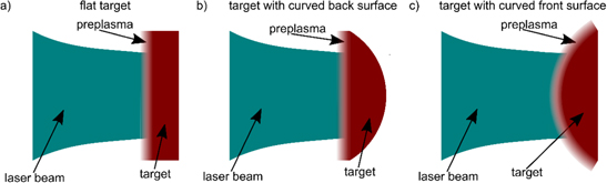
Figure 1. The carbon targets used in the simulations.
Download figure:
Standard image High-resolution imageAn infrared laser with a wavelength of 1.05 μm, a circular polarisation and a pulse duration of 1 ps (FWHM) was chosen as the laser driver accelerating ions. The assumed laser pulse duration ensured obtaining an ion pulse of the length required for IFI (∼10 ps or shorter) in the 'far expansion zone', so at a distance from the ion source desired for real IFI systems (the duration of the ion pulse increases with increasing distance from the source in the case of a non-mono-energetic ion beam). It also enabled us to perform the simulations in an acceptable period of time (not more than ∼1 month for a single set of the laser and target parameters). Bearing in mind that the ion beam energy deposited in DT fuel should be ∼10 kJ or higher, and also taking into account the expected laser-to-ions energy conversion efficiency and the possibility of a significant loss of the ion beam energy during propagation of the beam from the ion source to the fuel [33], it was found that the laser energy should not be less than 100 kJ. On the other hand, for economic and technological reasons, this energy should not be greater than several hundred kJ. Considering the above limitations, the simulations were carried out for the laser pulse energy equal to 150 kJ, 200 kJ and 250 kJ. The width of the laser beam was set at dL = 20 μm (FWHM) so that at least not very far away from the ion source a significant part of the energy of the angularly divergent ion beam could be contained in the area with a diameter not larger than ∼40–50 μm [10, 21]. In addition, it enabled us to achieve the ion beam intensity and fluence values relevant for IFI. The laser beam shape in space (along the y-axis) and time was described using a super-Gaussian function with a power index equal to 6.
The numerical simulations were performed in the x, y space of dimensions 150 × 40 μm2. The time and space steps were equal to 4.44 as and 20 nm, respectively. The number of ion macro-particles was assumed to be 18.6 × 10⁶ (40 particles/cell) for 6 μm target and 36.9 × 10⁶ (40 particles/cell) for 12 μm target.
Based on the simulations, various characteristics of the laser-produced ion beams for both the 'near expansion zone' and 'far expansion zone' were determined and the effect of laser energy, the target thickness and shape as well as the RL on these characteristics were examined in detail.
3. Basic properties of the laser-driven ion beam and the ion acceleration mechanism
3.1. Ionising properties of the carbon ion beam
When an ultra-intense laser beam interacts with a target, the target atoms are ionised by an electric field of the beam and plasma is created in the laser-target interaction region. The plasma ions are additionally ionised by the strong electric field generated in the plasma as a result of the local imbalance between the positive charge of ions and the negative charge of the electrons surrounding the ions. The laser-induced 'ionisation wave' created in the interaction region follows a cloud of the laser-accelerated electrons propagating across the target and the remaining non-irradiated portion of the target is ionised by the electric field produced by these electrons inside the target. Such a picture of the ionisation of the carbon target can be seen in figure 2, where 2D spatial distributions of the ionisation level in the carbon target are shown for different periods of the laser-target interaction. The distribution of the ionisation level in the target is in-homogenous and changes over time, right up to approximately 200 fs from the moment the laser starts interacting with the target. Once that time passes, the whole target is ionised to the maximum possible value of Z = 6 despite the fact that during the period of 200 fs the laser beam penetrated the target to a depth of less than 1 μm (figure 3). The consequence of the in-homogeneous distribution of the ionisation level in the target is an in-homogeneous distribution of forces accelerating ions in the ionisation stage of laser-target interaction, which affects the formation of the ion beam also in the later stages of ion acceleration and the final characteristics of the beam. In earlier works dedicated to carbon ion acceleration for IFI [21, 31, 32, 35, 36, 38], the effect of dynamic and in-homogeneous target ionisation was ignored.
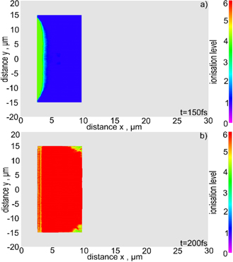
Figure 2. 2D spatial distributions of the ionisation level in the carbon target for different periods of the laser-target interaction. The laser energy EL = 200 kJ, the target thickness LT = 6 μm.
Download figure:
Standard image High-resolution image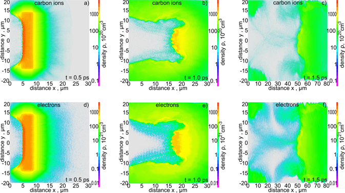
Figure 3. 2D spatial distributions of the ion density (a)–(c) and the electron density (d)–(f) in the simulation region for various stages of ion acceleration. EL = 200 kJ and LT = 6 μm.
Download figure:
Standard image High-resolution image3.2. Spatial characteristics of the ion beam and the ion acceleration mechanism
Spatial distributions of the quantities characterising the ion beam such as ion density, electron density or electric fields in the plasma and the evolution of these distributions over time are an important source of information on the course of the process of ion acceleration and acceleration mechanisms and are also helpful in developing methods for controlling ion beam parameters. 2D spatial distributions of the ion density and the electron density in the simulation region for various stages of ion acceleration are presented in figure 3, while the spatial distributions of the electric field perpendicular to the laser beam axis Ey and parallel to the laser beam axis Ex are shown in figure 4. In the early (t = 0.5 ps) and intermediate (t = 1 ps) stages of acceleration, a compact ion block with the density comparable to the initial density of the target is generated. Throughout the further stages of acceleration, the ion beam density decreases and in the late stage of acceleration (t = 1.5 ps), the mean density of the high-energy ion beam in the simulation area drops to ni ∼ 5 × 1022 cm−3. In all acceleration stages, the electron density distribution is almost identical to the ion density distribution and the vast majority of electrons co-move with ions. In fact, a dense block of quasi-neutral carbon plasma is generated, in which the charge of ions is almost completely neutralised by the charge of co-moving electrons. Thanks to this, the Coulomb repulsion between the ions is insignificant, and thus it is possible to produce an ion beam with a very high density desired in IFI-related applications. However, a spatial structure of the ion (plasma) beam is complex and inhomogeneous. One of the main reasons for the observed inhomogeneities, particularly pronounced in the intermediate acceleration stage (figures 3(b) and (e)), are plasma instabilities. Possible mechanisms producing these instabilities are discussed, for example, in [68–70].
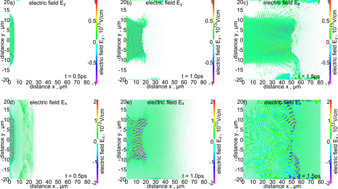
Figure 4. 2D spatial distributions of the electric fields perpendicular to the laser beam axis Ey (a)–(c) and parallel to the laser beam axis Ex (d)–(f) in the simulation region for various stages of ion acceleration. EL = 200 kJ and LT = 6 μm.
Download figure:
Standard image High-resolution imageComparing the ion and electron distributions with the electric field distributions presented in figure 4, we can conclude that the ions are accelerated primarily by the RPA mechanism. RPA is accompanied by the sheath acceleration (SA) mechanism (TNSA-like mechanism) in which the ions are accelerated by the electric field generated in plasma by hot electrons separated from the ions by laser-induced ponderomotive forces. This mechanism begins to dominate when the direct interaction of the laser pulse with the target terminates. Unfortunately, both RPA and SA drive ions not only along the laser beam axis but also in a radial direction and, as a result, the ion beam is angularly divergent (see further). The contribution of RPA and SA (TNSA) to the ion acceleration process is illustrated even better in figure 5, where spatial profiles of the ion density, the electron density and the electric field accelerating ions, Ex , along the laser beam axis at the early and late stages of ion acceleration are shown. In both stages, the RPA field is significantly stronger than the TNSA field, and the first one delivers most of the energy transferred from the laser to the ion beam. The TNSA field penetrates far behind the dense ion (plasma) block carrying the majority of the ion beam energy and this field primarily drives ions with the highest velocities. This field exists in plasma longer than the ponderomotive pressure accelerating the dense ion block and also occurs at t > 1.5 ps. However, in this final phase of acceleration, only a relatively small number of ions moving in front of the ion block is accelerated by this field, while the vast majority of ions concentrated in the block move inertially (ballistically). The result of this final acceleration phase may therefore be an increase in the maximum energy in the ion energy spectrum, while the influence of this acceleration phase on the parameters of the ion beam determining fuel ignition, such as fluence, intensity and energy of the ion beam as well as the mean ion energy, should not be significant. Taking into account the above physical premises and technical limitations of the supercomputer used, the simulation time was limited to 1.5 ps, i.e. the period of time after which the interaction of the laser with the target is practically terminated and further ion acceleration has little effect on the parameters of the ion beam important for IFI. This made it possible to perform a single cycle of calculations (for one set of input parameters) in a reasonable, technically acceptable time of about one month.
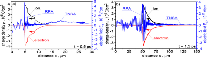
Figure 5. Spatial profiles of the ion density, the electron density and the electric field accelerating ions, Ex , along the laser beam axis at the early (a) and late (b) stages of ion acceleration. EL = 200 kJ and LT = 6 μm.
Download figure:
Standard image High-resolution imageThe above-described properties of the ion acceleration process enabled us to determine the parameters of the ion beam in the 'far-expansion zone' by adopting the simplifying assumption that outside the PIC simulation region, ions move ballistically. This assumption generally leads to the ion beam parameters being underestimated in the 'far-expansion zone'. However, taking into account that the values of fluence, intensity and 'useful' energy of the ion beam change by more than an order of magnitude in the considered range of distance x from the target (see e.g. figures 17, 18 and 20), underestimating these values in the 'far expansion zone' even by several dozen percent as a result of this assumption does not affect the main conclusions drawn from our computations.
3.3. The ion energy spectra
The ion energy spectra for all accelerated ions and for ions passing through an aperture with a diameter of 50 μm placed 50 μm behind the target are presented in figure 6. In turn, figure 7 shows the energy spectra for ions passing through a 50 μm aperture placed 50 μm, 100 μm and 500 μm behind the target. For a better visualisation of the structure of these spectra, they were presented using both the linear scale and logarithmic scale on the vertical axis. The spectra are wide since both RPA and SA contribute to the ion acceleration mechanism. The spectrum for all accelerated ions has a two-peak structure. The second peak in the spectrum is formed by ions propagating near the axis of the ion beam, so the ions that can be used to ignite the fuel. This high-energy part of the spectrum is quasi-mono-energetic with the standard deviation of ions energies equals to  . The shape of the spectrum for ions passing through the 50 μm aperture relatively weakly depends on the distance from the target, and the mean ion energy is rather close to that required for IFI. Unfortunately, the relatively large effective spectrum width and a long high-energy tail in the spectrum reaching energy above 2.5 GeV prevents the efficient and well-localised deposition of the ion beam energy into the fuel.
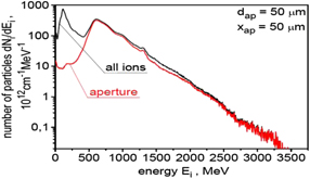
Figure 6. The energy spectra of ions presented using the logarithmic scale on the vertical axis for all accelerated ions and for ions passing through an aperture with a diameter of 50 μm placed 50 μm behind the target. EL = 200 kJ and LT = 6 μm.
Download figure:
Standard image High-resolution image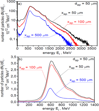
Figure 7. The energy spectra of ions presented using the logarithmic scale (a) and the linear scale (b) on the vertical axis for ions passing through an aperture with a diameter of 50 μm placed 50 μm, 100 μm and 500 μm behind the target. EL = 200 kJ and LT = 6 μm.
Download figure:
Standard image High-resolution image3.4. The ion beam fluence
Ion beam fluence is one of the key parameters determining the possibility of fuel ignition in IFI systems. The absolute values of fluence as well as its spatial distribution and the amount of beam energy in the area corresponding to the region with high fuel density are important (it is usually assumed that this area has a diameter of not more than 50 μm [10, 21]). In addition, for the efficient transport of ion beam energy from the ion source to the fuel, the angular distribution of fluence in the beam is crucial. The above ion beam characteristics for the laser and target parameters adopted in this section are demonstrated in figures 8 and 9.
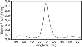
Figure 8. The angular distribution of ion beam fluence in the x–y plane. EL = 200 kJ and LT = 6 μm.
Download figure:
Standard image High-resolution image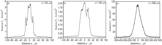
Figure 9. The spatial distribution of ion beam fluence in the x–y plane recorded at a distance of 50 μm (a), 100 μm (b) and 500 μm (c) behind the target. In the calculations of absolute values of the ion beam fluence, a correction related to the three-dimensional expansion of the ion beam was taken into account. EL = 200 kJ and LT = 6 μm.
Download figure:
Standard image High-resolution imageFigure 8 presents the angular distribution of ion beam fluence in the x–y plane. The fluence is strongly piled up around the laser beam axis, and the effective angular divergence (FWHM) of the ion beam is ∼20 deg. However, a significant portion of ions are emitted at large angles to the axis (up to 90 deg), and these ions are not useful in terms of fuel ignition. The main reason for this wide-angle ion emission is the radial ponderomotive forces generated in the plasma as a result of the heterogeneous (super-Gaussian) intensity distribution in the laser beam as well as the complex structure of electric fields induced in plasma in both the early and the late stages of ion acceleration (figure 4).
The spatial distribution of ion beam fluence in the x–y plane recorded at a distance of 50 μm, 100 μm and 500 μm behind the target is shown in figure 9. While calculating the absolute values of the ion beam fluence, a correction related to the three-dimensional expansion of the ion beam (3D correction) was taken into account. To account for this correction, it was assumed that the distribution of fluence in the x–z plane is the same as in the x–y plane. It can be seen that as the distance from the target increases, peak fluence decreases rapidly, the fluence distribution widens and its shape changes. The main reason for these changes is the angular divergence of the ion beam. At distances from the target ⩽100 μm, the peak fluence significantly exceeds 1 GJ cm−2, most of the ion beam energy is concentrated in the area <50 μm and the beam energy within this area is greater than 10 kJ (31 kJ at a distance of 50 μm and 18 kJ at a distance of 100 μm). Thus, these parameters are higher than or comparable with the values of the fluence and energy of the beam predicted to be sufficient to ignite the fuel (see introduction). At a distance of x = 500 μm, the effective width of the fluence distribution is ∼150 μm and the peak fluence and beam energy in an area <50 μm are much smaller than those required for IFI (the beam energy equals to 1.5 kJ).
3.5. The ion beam intensity and duration
Ignition of the fusion target by an ion beam in the IFI scenario is possible when the beam intensity is sufficiently high, and the ion beam energy is deposited in the target in a short period of time usually not longer than about 20 ps. The run of the ignition process is therefore determined not only by the absolute value of the effective beam intensity but also by the duration and shape of the ion pulse. Figure 10 presents the temporal shape of the ion pulse recorded 50 μm, 100 μm and 500 μm behind the target for the laser and target parameters assumed in this section. The ion pulse intensity is averaged over the area of aperture dap = 50 μm and to calculate the absolute values of the intensity, the 3D correction was applied. As the distance from the target increases, the peak intensity as well as the duration and shape of the ion pulse change significantly. The duration of the ion pulse increases from ∼0.5 ps at x = 50 μm to ∼3 ps at x = 500 μm, and the reason for the observed elongation of the pulse is the dispersion of ion velocities. The rapid drop in the peak intensity with the distance x seen in the figure is the result of the ion velocity dispersion and the angular divergence of the ion beam, with the angular beam divergence being crucial here. The peak intensity is extremely high and even at a distance from the target ∼0.5 mm it reaches the value comparable to that required for IFI (∼1020 W cm−2).
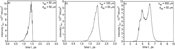
Figure 10. The temporal shape of the ion pulse recorded 50 μm (a), 100 μm (b) and 500 μm (c) behind the target. The ion pulse intensity is averaged over the area of aperture dap = 50 μm. In the calculations of absolute values of the intensity, a correction related to the three-dimensional expansion of the ion beam was taken into account. EL = 200 kJ and LT = 6 μm.
Download figure:
Standard image High-resolution imageThe dependence of the ion beam characteristics presented in this section on laser energy as well as the thickness and shape of the carbon target will be discussed in the next two sections.
4. The effect of laser energy on the ion beam characteristics
We will demonstrate the influence of laser energy on the characteristics of the ion beam for a fixed duration of the laser pulse and a fixed width of the laser beam irradiated carbon target with a reference thickness of 6 μm. The range of changes in laser energy from 150 kJ to 250 kJ adopted in the numerical simulations corresponds to the range of changes in the peak intensity of the laser pulse from 3.9 × 10²² W cm−2 to 6.5 × 10²² W cm−2.
The influence of laser energy on the energy spectra of the carbon ion beam is shown in figures 11 and 12. Figure 11 presents the energy spectra for all ions accelerated at various laser energies, while figure 12 shows the energy spectra for ions passing through an aperture with a diameter of 50 μm placed 50 μm (a) and 500 μm (b) behind the target. As one would expect, an increase in laser energy leads to an increase in ion energy; however, the shape of the spectrum changes relatively weakly with a change in laser energy. As the distance from the target increases, the number of ions passing through the 50 μm aperture decreases, but the shape of the spectrum and the mean ion energy changes little with the increase of this distance. The dependence of the mean and maximum ion energy on laser energy for ions passing through the 50 μm aperture located 50 μm behind the target is shown in figure 13. Both of these ion energies increase approximately linearly with increasing laser energy. However, the increase in the mean ion energy is faster than the maximum energy, which is advantageous from the point of view of fuel ignition, since a long high-energy tail in the energy spectrum hinders the localised deposition of the ion beam energy to the fuel.
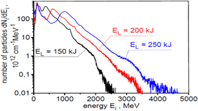
Figure 11. The energy spectra of ions presented using the logarithmic scale on the vertical axis for all ions accelerated at various laser energies. The target thickness LT = 6 μm.
Download figure:
Standard image High-resolution image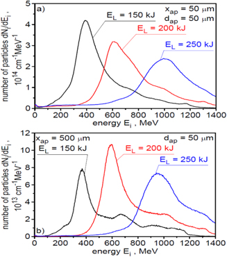
Figure 12. The energy spectra of ions accelerated at various laser energies and passing through an aperture with a diameter of 50 μm placed 50 μm (a) and 500 μm (b) behind the target. The target thickness LT = 6 μm.
Download figure:
Standard image High-resolution image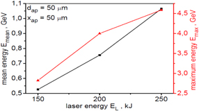
Figure 13. The mean and maximum ion energy as a function of laser energy for ions passing through an aperture with a diameter of 50 μm placed 50 μm behind the target. The target thickness LT = 6 μm.
Download figure:
Standard image High-resolution imageThe laser-to-ions energy conversion efficiency increases with the increase of laser energy. Nonetheless, the efficiency increase in the considered range of laser energy is relatively small (figure 14). The total energy conversion efficiency (conversion to all ions) is fairly high—it exceeds 20%. About 3/4 of the energy of all ions is carried by forward-accelerated ions passing through the 50 μm aperture located 50 μm from the target. At the laser energy of ∼200 kJ, the total energy of these ions is ∼30 kJ, so it significantly exceeds the energy required for the fuel ignition.
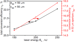
Figure 14. The laser-to-ions energy conversion efficiency for all the ions and for the ions passing through an aperture with a diameter of 50 μm placed 50 μm behind the target as a function of laser energy. The target thickness LT = 6 μm.
Download figure:
Standard image High-resolution imageThe influence of laser energy on the angular distribution of the ion beam fluence is presented in figure 15. The shape of the distribution changes relatively weakly with the change of the laser energy, while the effective distribution width (FWHM) decreases with the increase of laser energy. At the laser energy of 250 kJ, the effective angular divergence of the ion beam is slightly below 20 deg.
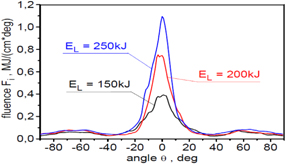
Figure 15. The angular distribution of ion beam fluence in the x–y plane, for ion beams produced with various laser energies. The target thickness LT = 6 μm.
Download figure:
Standard image High-resolution imageThe effect of laser energy on the spatial distribution of ion beam fluence at different distances from the target is shown in figure 16. The change in laser energy significantly affects both the shape of the distribution and the peak value of the beam fluence. The peak beam fluence grows rapidly with an increase in laser energy and an increase of this energy by a factor of ∼1.7 results in an increase in the peak fluence by a factor of ∼4 in both the near and far ion expansion zone. This considerable increase in the peak fluence is the result of the simultaneous increase in the number and energy of forward-accelerated ions with the increase in laser energy.
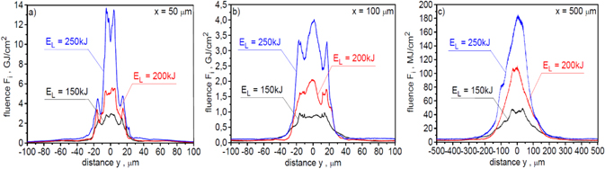
Figure 16. The spatial distribution of ion beam fluence in the x–y plane, recorded at a distance of 50 μm (a), 100 μm (b) and 500 μm (c) behind the target, for ion beams produced with various laser energies. In the calculations of absolute values of the ion beam fluence, a correction related to the three-dimensional expansion of the ion beam was taken into account. The target thickness LT = 6 μm.
Download figure:
Standard image High-resolution imageThe dependence of the peak ion beam fluence on the distance x from the target for different laser energies is shown in figure 17. In turn, figure 18 shows how the beam energy contained in the aperture with a diameter of 50 μm changes with the increase of this distance. Both of these beam parameters decrease rapidly with increasing distance x, and the reason for the observed decrease in their value is the angular divergence of the beam. At 250 kJ laser energy, these parameters reach the values predicted to be required for the fuel ignition (Fmax > 1 GJ cm−2, E > 10 kJ) only at a distance of x < 200 μm. At 150 kJ, this distance is even shorter and amounts to only ∼50–100 μm.
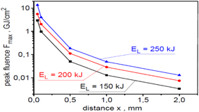
Figure 17. The peak fluence of ion beams produced with various laser energies as a function of the distance x from the target. In the calculations of absolute values of the fluence, a correction related to the three-dimensional expansion of the ion beam was taken into account. The target thickness LT = 6 μm.
Download figure:
Standard image High-resolution image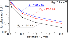
Figure 18. The dependence of the ion beam energy recorded inside the aperture with dap = 50 μm on the distance x from the target for ion beams produced with various laser energies. In the calculations of absolute values of the beam energy, a correction related to the three-dimensional expansion of the ion beam was taken into account. The target thickness LT = 6 μm.
Download figure:
Standard image High-resolution imageThe effect of laser energy on the shape and intensity of the ion pulse at different distances from the target is shown in figure 19. The change in laser energy considerably affects both the shape and the peak intensity of the ion pulse. The peak intensity grows very rapidly with an increase in laser energy and an increase of the laser energy by a factor of ∼1.7 results in an increase in the peak intensity by a factor of ∼6 at a short distance from the target (x = 50 μm) up to a factor ∼10 at a long distance from the target (x = 500 μm). This rapid increase in the peak intensity of the ion pulse is the result of a significant increase in both the number and energy of forward-accelerated ions with the increase in laser energy. The peak intensities are extremely high and even at x = 500 μm the peak intensity of the ion pulse produced by a 250 kJ laser reaches a value well above 1020 W cm−2.
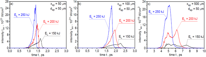
Figure 19. The temporal shapes of the ion pulses produced with various laser energies and recorded 50 μm (a), 100 μm (b) and 500 μm (c) behind the target. The ion pulse intensity is averaged over the area of aperture dap = 50 μm. In the calculations of absolute values of the intensity, a correction related to the three-dimensional expansion of the ion beam was taken into account. The target thickness LT = 6 μm.
Download figure:
Standard image High-resolution imageThe dependence of the peak intensity and duration of the ion pulse on the distance x from the target for different laser energies is shown in figure 20. The peak intensity decreases rapidly with increasing distance x due to both the angular divergence of the beam (main reason) and the ion velocity dispersion. However, at the laser energy ⩾200 kJ, the peak intensity reaches the values predicted to be required for the fuel ignition (∼1020 W cm−2) even at a relatively long distance from the target of ∼0.5 mm. Due to the ion velocity dispersion, the ion pulse duration increases linearly with an increase in the distance from the target, and the duration increase is the fastest for the lowest laser energy.
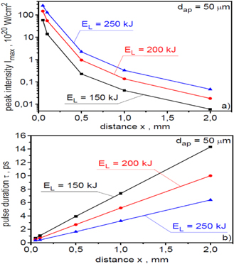
Figure 20. The peak intensity (a) and duration (b) of the ion pulses produced with various laser energies as a function of the distance x from the target. The ion pulse intensity is averaged over the area of aperture dap = 50 μm. In the calculations of absolute values of the intensity, a correction related to the three-dimensional expansion of the ion beam was taken into account. The target thickness LT = 6 μm.
Download figure:
Standard image High-resolution imageIn summary, laser energy significantly affects all ion beam parameters that are important for IFI. The increase in laser energy results in approximately a linear increase in mean ion energy; however, the increase in peak fluence and peak intensity of the ion beam is non-linear and much faster: an increase in laser energy from 150 kJ to 250 kJ results in an increase in the peak fluence by a factor of ∼4 and in the peak intensity even by a factor ∼10. At the same time, an increase in laser energy causes a reduction in the ion pulse duration as well as a reduction in the effective angular divergence of the ion beam.
5. The effect of target thickness on the ion beam characteristics
The target thickness, LT, is an important parameter of the laser-target interaction that significantly affects the run of the ion acceleration process and the characteristics of the produced ion beam. We will demonstrate the influence of LT on the ion beam characteristics by comparing the simulation results for a target with a 'reference' thickness of 6 μm with the results for a target with a thickness of 12 μm. The comparison is made for a laser energy of 150 kJ.
Figure 21 presents the ion energy spectra for all ions generated from the target with the thickness of 6 μm or 12 μm, and figure 22 shows the energy spectra for ions passing through the 50 μm aperture placed 50 μm or 500 μm behind the target. Both the shape of the energy distribution and the mean and maximum energies of ions generated from targets of different thicknesses are significantly different. As expected [37], the mean and maximum ion energy is higher for the thinner target while the number of accelerated ions, including ions propagating near the laser axis, is higher for the thicker target. Because the fluence and intensity of the ion beam depend on both the mean ion energy and the number of ions, the regularities shown in figures 21 and 22 suggest that reducing the target thickness does not have to lead to an increase in the beam fluence and intensity, and that there may be optimal target thicknesses at which these beam parameters reach maximum values [37].
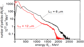
Figure 21. The energy spectra of ions presented using the logarithmic scale on the vertical axis for all ions produced from carbon targets of different thicknesses. The laser energy EL = 150 kJ.
Download figure:
Standard image High-resolution image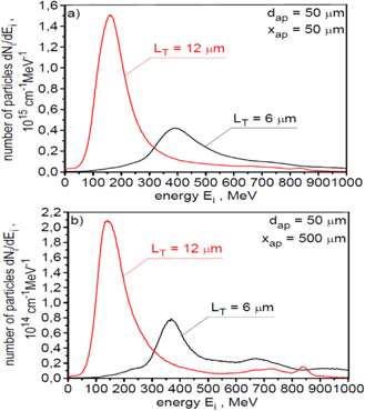
Figure 22. The energy spectra of ions produced from carbon targets of different thicknesses and passing through an aperture with a diameter of 50 μm placed 50 μm (a) and 500 μm (b) behind the target. The laser energy EL = 150 kJ.
Download figure:
Standard image High-resolution imageFigure 23 presents the angular distribution of the ion beam fluence for two considered targets, and a comparison of spatial distributions of the fluence for ion beams generated from these targets are shown in figure 24. The shapes of the distributions for both targets are similar; however, the peak fluence is higher for the thinner target. Since the fluence is proportional to both the mean ion energy and the number of ions, it means that the increase in the mean ion energy resulting from the smaller thickness of the target compensates with excess for the reduction in the number of ions. The difference between the peak fluences of the ion beams generated from the 6 μm and 12 μm targets increases with increasing distance x from the target because the effective divergence of the beam generated from the thinner target is slightly smaller. This is also demonstrated by figures 25 and 26, which show the dependence of the peak beam fluence (figure 25) and the 'useful' beam energy (figure 26) on the distance from the target.
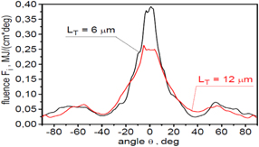
Figure 23. The angular distributions of ion beam fluence in the x–y plane, for ion beams produced from carbon targets of different thicknesses. The laser energy EL = 150 kJ.
Download figure:
Standard image High-resolution image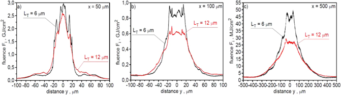
Figure 24. The spatial distributions of ion beam fluence in the x–y plane, recorded at a distance of 50 μm (a), 100 μm (b) and 500 μm (c) behind the target, for ion beams produced from carbon targets of different thicknesses. In the calculations of absolute values of the ion beam fluence, a correction related to the three-dimensional expansion of the ion beam was taken into account. The laser energy EL = 150 kJ.
Download figure:
Standard image High-resolution image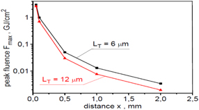
Figure 25. The peak fluence of ion beams produced from carbon targets of different thicknesses as a function of the distance x from the target. In the calculations of absolute values of the fluence, a correction related to the three-dimensional expansion of the ion beam was taken into account. The laser energy EL = 150 kJ.
Download figure:
Standard image High-resolution image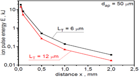
Figure 26. The dependence of the ion beam energy recorded inside the aperture with dap = 50 μm on the distance x from the target for ion beams produced from carbon targets of different thicknesses. In the calculations of absolute values of the beam energy, a correction related to the three-dimensional expansion of the ion beam was taken into account. The laser energy EL = 150 kJ.
Download figure:
Standard image High-resolution imageThe impact of the target thickness on the peak intensity as well as the shape and duration of the ion pulse are demonstrated in figures 27 and 28. Because the intensity of the ion beam is proportional to the mean energy of ions in the 3/2 power, an increase in this energy seen in figure 22 results in an increase in the intensity of the beam greater than the increase in the beam fluence (figure 24) and, consequently, the differences between the beam intensity distributions of ions generated from targets of different thicknesses are greater than in the case of fluence distributions. In the case under consideration, the peak beam intensity for the 6 μm target is even a factor 3–4 higher than for the 12 μm target.
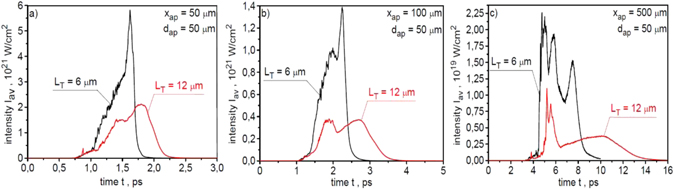
Figure 27. The temporal shapes of the ion pulses produced from carbon targets of different thicknesses and recorded 50 μm (a), 100 μm (b) and 500 μm (c) behind the target. The ion pulse intensity is averaged over the area of aperture dap = 50 μm. In the calculations of absolute values of the intensity, a correction related to the three-dimensional expansion of the ion beam was taken into account. The laser energy EL = 150 kJ.
Download figure:
Standard image High-resolution image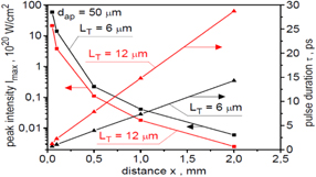
Figure 28. The peak intensity and duration of the ion pulses produced from carbon targets of different thicknesses as a function of the distance x from the target. The ion pulse intensity is averaged over the area of aperture dap = 50 μm. In the calculations of absolute values of the intensity, a correction related to the three-dimensional expansion of the ion beam was taken into account. The laser energy EL = 150 kJ.
Download figure:
Standard image High-resolution imageThe above results show that by carefully adjusting the target thickness to the laser parameters it is possible to significantly improve almost all of the ion beam parameters important for IFI.
6. The effect of the target shape on the ion beam characteristics
Like the thickness of the target, its shape can also affect the parameters of the ion beam accelerated by the laser. We will demonstrate this with the example of targets with the shapes shown in figure 1: a flat target with a thickness of 6 μm, a target with a curved (spherical) rear surface and a target with a curved front surface. It was assumed for the simulations that the area of each of the three targets in the x–y plane is the same, and the laser energy is equal to 250 kJ.
Figure 29 presents 2D spatial distributions of the ion density (a)–(c) and the electric fields perpendicular to the laser beam axis Ey (d)–(f) in the simulation region for carbon targets with various shapes shown in figure 1 and the simulation time t = 1 ps. Differences in ion density distributions and Ey field distributions at this acceleration stage are relatively small for the targets being considered. Both in the case of a flat target and targets with curved surfaces, a dense ion (plasma) block is formed with a density comparable to the initial density of the target. The average speed of the ion block is the highest for the flat target, but plasma instabilities that deteriorate the quality of the ion beam also develop fastest in this case.
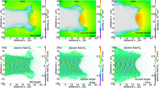
Figure 29. 2D spatial distributions of the ion density (a)–(c) and the electric fields perpendicular to the laser beam axis Ey (d)–(f) in the simulation region for carbon targets with various shapes. The simulation time t = 1 ps, EL = 250 kJ and LT = 6 μm.
Download figure:
Standard image High-resolution imageThe higher speed of the ion block from the flat target is visible in the ion energy spectra shown in figure 30, which presents the energy spectra of ions produced from carbon targets with various shapes and passing through an aperture with a diameter of 50 μm, placed 50 μm and 500 μm behind the target. Although the shapes of the energy spectra are similar, the ion beam generated from the flat target has the highest mean ion energy. The number of ions passing through the 50 μm aperture is, however, the smallest for this target. This is a result of the larger angular divergence of the ion beam generated from the flat target, as can be seen in figure 31, presenting the angular distributions of the ion beam fluence for targets of different shapes. The main reason for the smaller angular divergence of ion beams produced from targets with a curved surface is the better matching of the intensity/fluence distribution in the laser beam to the distribution of the areal atom density in targets with a curved surface. The result of a smaller angular divergence of the ion beam generated from targets with curved surfaces is a higher peak fluence of the beam at a large distance from the target (figure 32). In the cases considered, the highest peak fluence of the beam is obtained for the target with a curved back surface; at x = 500 μm, the peak fluence for this target is more than twice as high as for the flat target.
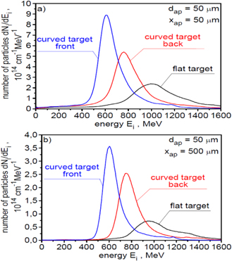
Figure 30. The energy spectra of ions produced from carbon targets with various shapes and passing through an aperture with a diameter of 50 μm placed 50 μm (a) and 500 μm (b) behind the target. EL = 250 kJ and LT = 6 μm.
Download figure:
Standard image High-resolution image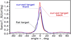
Figure 31. The angular distributions of ion beam fluence in the x–y plane, for ion beams produced from carbon targets with various shapes. EL = 250 kJ and LT = 6 μm.
Download figure:
Standard image High-resolution image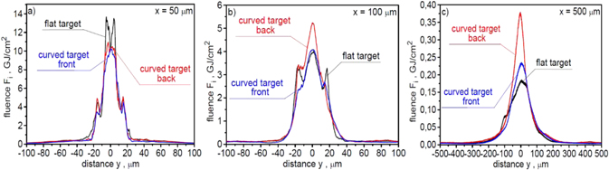
Figure 32. The spatial distributions of ion beam fluence in the x–y plane, recorded at a distance of 50 μm (a), 100 μm (b) and 500 μm (c) behind the target, for ion beams produced from carbon targets with various shapes. In the calculations of absolute values of the ion beam fluence, a correction related to the three-dimensional expansion of the ion beam was taken into account. EL = 250 kJ and LT = 6 μm.
Download figure:
Standard image High-resolution imageFigures 33 and 34 show the dependence of peak fluence (figure 33) and 'useful' energy (figure 34) of an ion beam generated from targets of different shapes on a distance x from the target. The decrease in peak fluence and 'useful' energy of the beam with an increase in x is slower for targets with a curved surface, meaning that these parameters retain the values required for IFI at distances x larger than for a flat target. In addition, the peak intensities of ion pulses generated from the targets with a curved surface are higher than in the case of a flat target, with the peak intensity for such targets decreasing more slowly with increasing distance from the target (figures 35 and 36). The highest peak intensities are obtained for a target with a curved back surface; at x = 500 μm, this intensity is a factor of three higher than for the flat target. The shape of the target, however, affect the duration of the ion pulse relatively weakly (figure 36(b)).
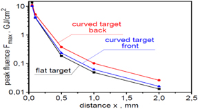
Figure 33. The peak fluence of ion beams produced from carbon targets with various shapes as a function of the distance x from the target. In the calculations of absolute values of the fluence, a correction related to the three-dimensional expansion of the ion beam was taken into account. EL = 250 kJ and LT = 6 μm.
Download figure:
Standard image High-resolution image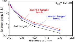
Figure 34. The dependence of the ion beam energy recorded inside the aperture with dap = 50 μm on the distance x from the target for ion beams produced from carbon targets with various shapes. In the calculations of absolute values of the beam energy, a correction related to the three-dimensional expansion of the ion beam was taken into account. EL = 250 kJ and LT = 6 μm.
Download figure:
Standard image High-resolution image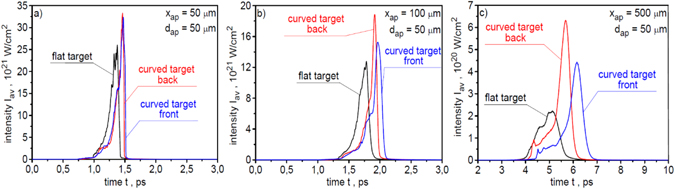
Figure 35. The temporal shapes of the ion pulses produced from carbon targets with various shapes and recorded 50 μm (a), 100 μm (b) and 500 μm (c) behind the target. The ion pulse intensity is averaged over the area of aperture dap = 50 μm. In the calculations of absolute values of the intensity, a correction related to the three-dimensional expansion of the ion beam was taken into account. EL = 250 kJ and LT = 6 μm.
Download figure:
Standard image High-resolution image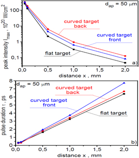
Figure 36. The peak intensity (a) and duration (b) of the ion pulses produced from carbon targets with various shapes as a function of the distance x from the target. The ion pulse intensity is averaged over the area of aperture dap = 50 μm. In the calculations of absolute values of the intensity, a correction related to the three-dimensional expansion of the ion beam was taken into account. EL = 250 kJ and LT = 6 μm.
Download figure:
Standard image High-resolution imageIn summary, the shape of the target significantly affects the characteristics of the generated ion beam, so that, by properly matching the shape of the target surface to the distribution of the laser beam intensity, it is possible to increase the peak intensity, peak fluence and 'useful' energy of the ion beam even several times.
7. Synchrotron radiation and its effect on parameters of the ion beam
When the intensity of the laser beam approaches what is known as ultra-relativistic intensity (∼1023 W cm−2 or higher), the interaction of the beam with a solid or plasma target may be accompanied by the emission of short-wavelength synchrotron radiation, whose source is laser-driven relativistic electrons. In recent years, the laser-induced generation of synchrotron radiation has become a hot topic studied both theoretically and numerically in many works (e.g. [30, 56–59, 71–73]). In some of these works, it has been shown that, when the femtosecond laser pulse of ultra-relativistic intensity interacts with the target, a significant percentage of the energy of laser-driven plasma electrons can be converted into synchrotron radiation [30, 56–59, 71]. Since at least some of these electrons are the source of electric fields accelerating ions in the plasma, RL of electron energy can affect the ion acceleration process and thus the parameters of the generated ion beam. Here we show that, under laser-target interaction conditions relevant for IFI, even at laser intensities well below 1023 W cm−2, extremely strong (tens of PW) bursts of synchrotron radiation are produced and electron energy losses associated with its emission have a significant impact on the parameters of the ion beam determining the ignition of the fuel.
Figure 37 presents 2D spatial distributions of the radiation power density for various stages of ion acceleration. Comparing this figure with figures 3(d)–(f) and 4(a)–(c), it can be seen that radiation is generated mainly in the region of direct interaction of the laser field with fast electrons produced by the laser. The density of radiation power in the source is extremely high, up to ∼1025–1026 W cm−3. The analysis of the energy spectra of fast electrons produced in the plasma showed that the energies of the vast majority of these electrons, both forward and backward accelerated, lie in the ultra-relativistic region: the maximum electron energies reach several hundred MeV, and their mean energies are ∼25–30 MeV. This suggests that at least part of the energy spectrum of emitted photons lies in the energy range >1 MeV, and therefore in the energy region of gamma rays [57, 71, 73]. The total power of the emitted radiation reaches 70 PW (in peak), and the duration of the emission is fairly close to the duration of the laser pulse (figure 38). The efficiency of energy conversion from laser to radiation is ∼30%, and the total energy of the radiation is ∼60 kJ. It can be expected that such a powerful burst of short-wavelength radiation will significantly disturb the diagnostics used in the IFI fusion system, and that gamma photons from the high-energy region of the radiation spectrum can be dangerous for the fusion infrastructure and lead to the destruction of the structural and optical materials of this infrastructure.
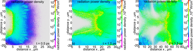
Figure 37. 2D spatial distributions of the radiation power density for various stages of ion acceleration. EL = 200 kJ and LT = 6 μm.
Download figure:
Standard image High-resolution image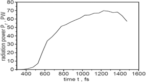
Figure 38. The power of synchrotron radiation emitted by relativistic electrons produced at the laser-carbon target interaction as a function of time. EL = 200 kJ and LT = 6 μm.
Download figure:
Standard image High-resolution imageA more detailed discussion of the properties of the synchrotron radiation and possible mechanisms of the radiation generation is beyond the scope of this paper and will be carried out elsewhere. Below, we will focus our attention on the impact of losses associated with the emission of this radiation (RL) on the ion beam parameters important for IFI.
The effect of RL on the energy spectrum of ions generated from a 6-um target by a 200 kJ laser pulse is shown in figure 39. RL relatively weakly affects the overall shape of the energy spectrum, though they cause a large shift of the high-energy peak in the spectrum towards lower energies, and lead to a significant reduction in both the mean and maximum ion energy. The effect of RL on the low-energy part of the spectrum—dominated by ions emitted at a large angle to the laser axis (figures 6 and 7)—is smaller and the change in the mean ion energy of this 'unusable' (for IFI) part of the ion beam is insignificant.
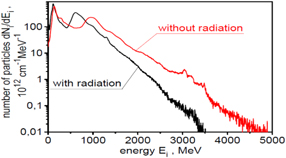
Figure 39. The ion energy spectra obtained in the simulation with included RL (black line) and in the simulation without RL (red line) presented using the logarithmic scale on the vertical axis. EL = 200 kJ and LT = 6 μm.
Download figure:
Standard image High-resolution imageThe reduction of the mean ion energy and the number of high-energy ions due to RL results in a decrease in the value of other parameters of the ion beam, in particular the peak fluence and peak intensity of the ion beam. This is demonstrated by figures 40 and 41, which show that the peak ion beam fluence and the peak beam intensity are reduced by a factor of ∼2 due to the emission of synchrotron radiation.
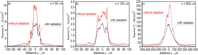
Figure 40. The spatial distributions of ion beam fluence in the x–y plane, recorded at a distance of 50 μm (a), 100 μm (b) and 500 μm (c) behind the target, for the case with RL (black line) and without RL (red line). In the calculations of absolute values of the ion beam fluence, a correction related to the three-dimensional expansion of the ion beam was taken into account. EL = 200 kJ and LT = 6 μm.
Download figure:
Standard image High-resolution image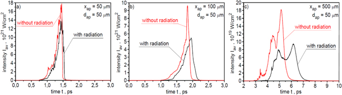
Figure 41. The temporal shapes of the ion pulses recorded 50 μm (a), 100 μm (b) and 500 μm (c) behind the target, for the case with RL (black line) and without RL (red line). The ion pulse intensity is averaged over the area of aperture dap = 50 μm. In the calculations of absolute values of the intensity, a correction related to the three-dimensional expansion of the ion beam was taken into account. EL = 200 kJ and LT = 6 μm.
Download figure:
Standard image High-resolution image
A summary of the effect of RL on the various ion beam parameters important for IFI is given in table 1. This effect is significant in relation to all beam parameters shown in the table and increases as the distance from the target increases. The synchrotron radiation emission accompanying ion acceleration has the greatest effect on the peak values of fluence, intensity and power of the ion beam, and at a distance of ∼0.5 mm from the target these values are lower by a factor of ∼2, due to RL. This also means that RL shortens the distances from the target at which it is possible to achieve the ion beam parameters required for IFI.
Table 1. Comparison of ion beam parameters obtained from the simulation taking into account the RL and from the simulation without these losses. EL = 200 kJ and LT = 6 μm.
| x = 50 μm | x = 500 μm | |||||||||||
|---|---|---|---|---|---|---|---|---|---|---|---|---|
| Emean GeV | EmaxGeV | Imax 1020 W cm−2 | Fmax GJ cm−2 | Eb kJ | Pb PW | Emean GeV | Emax GeV | Imax 1020 W cm−2 | Fmax GJ cm−2 | Eb kJ | Pb PW | |
| With RL | 0.76 | 4.00 | 148 | 5.59 | 31.1 | 146 | 0.77 | 2.99 | 0.95 | 0.11 | 1.5 | 0.94 |
| Without RL | 1.08 | 5.47 | 178 | 10.1 | 36.4 | 176 | 1.19 | 4.89 | 1.83 | 0.21 | 1.83 | 1.80 |
8. Summary and conclusions
In summary, systematic numerical studies of laser-driven acceleration of carbon ions for high-gain fusion in the IFI scenario have been carried out, and the possibility of achieving the parameters of the ion beam predicted as necessary for the fusion target ignition has been analysed. The numerical simulations of the process of laser-target interaction and ion acceleration were conducted using multidimensional (2D3V) particle-in-cell code, taking into account the dynamic ionisation of the carbon target and synchrotron radiation emitted by laser-driven relativistic electrons. A set of ion beam characteristics determining the fusion target ignition, in particular ion energy spectra, spatial and angular distributions of ion beam fluence, time shapes of ion pulses, ion beam energy and power, and peak values of the beam fluence and intensity, was determined for both the 'near expansion zone' and 'far expansion zone' of the ion beam. The effect of energy/intensity of 1 ps infrared (1.05 μm) laser in the energy range from 150 kJ to 250 kJ as well as the target thickness and shape were examined in detail.
It has been found that, under the conditions of the laser-target interaction considered in the paper, the dominant mechanism of ion acceleration is the RPA mechanism, though the influence of the TNSA-like mechanism in the acceleration process is also noticeable. The energy spectrum of ions has a two-peak structure regardless of the laser energy and the thickness and shape of the target. The second, high-energy peak in the spectrum, with a width (FWHM) ∼35%–40%, is formed mainly by ions propagating at relatively small angles to the laser axis, so that part of the ion beam that can be considered 'useful' from the point of view of the fusion target ignition. The mean ion energy in the high-energy peak depends on the laser energy and target parameters and lies in the energy range ∼400 MeV to 900 MeV, i.e. the range of ion energy that can be considered relatively well matched to IFI requirements. However, the relatively large spectrum width and long tail in the spectrum approaching several GeV prevents the well-localised and efficient deposition of the ion beam energy into the fusion fuel.
It has been shown that, while the mean ion energy increases with an increase in laser energy/intensity approximately linearly, the peak ion beam fluence and peak beam intensity increases much more rapidly: an increase in laser energy/intensity by a factor of ∼1.7 results in an increase of the peak fluence by a factor of ∼4 and a peak intensity by as much as a factor of ∼10. The increase in laser energy leads to a slight reduction in the angular divergence of the ion beam, which means that an increase in the peak fluence and intensity with laser energy is the fastest in the 'far expansion zone'.
The ion beam parameters can be considerably increased with the proper selection of the target thickness and shape. It has been shown that a change in the carbon target thickness from 12 μm to 6 μm results in an increase in the peak ion beam fluence by a factor of ∼1.5–2, the mean ion energy by a factor of ∼2.5–3 and the peak beam intensity by a factor of ∼3–4, and an increase in the values of these parameters is higher in the 'far expansion zone'. The shape of the target also significantly affects the ion beam parameters. Replacing the flat target with a target with a curved (spherical) back surface resulted in a reduction in the angular divergence of the ion beam and an increase, in the 'far expansion zone', of the peak beam fluence by a factor of ∼2 and the peak beam intensity by a factor of ∼3. These results prove that, by carefully selecting the thickness and shape of the target, it is possible to increase the ion beam parameters important for IFI even several times (∼5 or more).
It has been found that, under laser-target interaction conditions relevant for IFI, ion acceleration is accompanied by a strong emission of short-wavelength synchrotron radiation. At an energy and intensity of 1 ps laser pulse ∼200 kJ and 5 × 10²² W cm−2, respectively, a picosecond synchrotron radiation pulse with ∼60 kJ energy and peak power approaching 70 PW is generated. RL associated with the emission of this radiation significantly reduce (by a factor of ∼1.5–2) all ion beam parameters important for IFI.
The ion beam parameters depend significantly on the distance x from the target. At the laser and target parameters considered in the paper, the ion beam parameters such as peak beam fluence, peak beam intensity and 'useful' beam energy reach, in the 'near expansion zone' (x ∼ 50–100 μm), values far exceeding those predicted as required for IFI. In particular, the peak intensity and fluence of the beam exceeds 5 × 10²¹ W cm−2 and 2 GJ cm−2, respectively, while the 'useful' beam energy approaches 30 kJ. The shape of the 'useful' part of the ion energy spectrum depends weakly on x, with the mean ion energy being relatively well matched to the required values in both the 'near expansion zone' and the 'far expansion zone'. However, due to the angular divergence of the ion beam, the fluence and intensity of the beam, as well as the 'useful' beam energy, decreases rapidly as x increases. As a result, achieving the required values of these parameters is possible only at distances from the target not greater than several hundred (∼200–400) μm.
In conclusion, we found that a picosecond IR laser with an energy of ∼200 kJ enables the ion beam parameters required for high-gain fusion in the IFI scenario to be achieved, even with a simple non-optimised carbon target, but only at small distances (⩽100 μm) from the target. At such distances, the 'useful' energy of the ion beam approaches 30 kJ while the peak intensity and fluence of the beam exceeds 5 × 10²¹ W cm−2 and 2 GJ cm−2, respectively. The parameters of the ion beam can be significantly improved (the fluence and intensity of the beam can be increased by as much as a factor ⩾5) by carefully selecting the thickness of the target and adjusting its shape to the intensity distribution in the laser beam. However, even with an optimised target, achieving the values of the ion beam parameters required for IFI is possible only at distances from the target not larger than several hundred micrometres. Achieving such values of beam parameters at longer distances from the target (∼1 mm), which is desired in the IFI fusion systems, seems possible, but would require the use of higher laser energies and/or more sophisticated acceleration schemes ensuring a greater concentration of ion energy near the beam axis (e.g. [31, 74, 75]) and the reduction of the angular beam divergence. We showed, for the first time, that, under laser-target interaction conditions relevant for IFI, ion acceleration is accompanied by the emission of picosecond pulses of short-wavelength synchrotron radiation of very high power (tens of PW) and energy (tens of kJ). Apart from the fact that this emission is a source of significant energy losses in the ion beam, such strong bursts of short-wavelength radiation can significantly disturb the diagnostics used in the IFI fusion system, and gamma photons from the high-energy region of the radiation spectrum can potentially be dangerous for the fusion infrastructure and cause the destruction of the structural and optical materials of this infrastructure.
The extremely intense picosecond ion beams demonstrated in the paper are unattainable with conventional RF-driven accelerators. Their peak fluence, intensity and power are at least 2–3 orders of magnitude higher, their durations are 3–4 orders of magnitude shorter, and their density is 10 orders of magnitude higher than those obtained in the largest conventional accelerators. In addition to IFI, ion or proton beams of such extreme parameters can also be used in other ICF options, for example in proton–boron fusion [18, 19, 76]. Moreover, they can be a unique research tool in new, as yet unexplored areas of fundamental research in nuclear physics, high energy-density physics or material science. The powerful picosecond bursts of synchrotron X/γ radiation revealed in our simulations may pose a threat to the fusion infrastructure on the one hand, and on the other hand, they can potentially be used for research, e.g. in nuclear physics or for material structure studies.
Acknowledgments
This work was supported in part by the EUROfusion Consortium (the RoHGIFE project No. ENR-IFE19.CCFE-01) and has received partial funding from the Euratom research and training programme 2014–2018 and 2019–2020 under Grant agreement No. 633053. The views and opinions expressed herein do not necessarily reflect those of the European Commission. This scientific work was also supported by Polish Ministry of Science and Higher Education within the framework of the scientific financial resources in the year 2020, allocated for the realization of the international co-financed project. The simulations were carried out with the support of the Interdisciplinary Centre for Mathematical and Computational Modelling (ICM), University of Warsaw under Grant No. G57-20 and the Poznan Supercomputing and Networking Centre under Grant No. 417.