


Abstract
It is well established that edge localized modes can be entrained to the frequency of applied global magnetic perturbations. These perturbations are delivered to the plasma using the vertical control system field coil currents. These field coils are part of an active control system that is required to maintain the plasma in a steady state. We perform time domain timeseries analysis of natural ELMing when there are no applied perturbations in the ASDEX Upgrade tokamak. We find that the plasma can transition into a state in which the control system field coil currents continually oscillate and are synchronized with oscillations in characteristic plasma parameters such as plasma edge position and total MHD energy. These synchronous oscillations have a one-to-one correlation with the naturally occurring ELMs; the ELMs all occur when the control system coil current is around a specific temporal phase. Large and small ELMs may be distinguished by the amplitude of inward movement of the edge following an ELM. Large ELMs are then found to occur preferentially around a specific temporal phase of the vertical position control coil current. Small ELMs are most likely in antiphase to this. The large and small natural ELMs occur at the opposite extrema of the oscillations in the control system vertical position control coil current. The control system coil current phase may thus provide a useful parameter to order the observed ELM dynamics. We have identified a class of natural ELMing which is a self-entrained state, in which there is a continual non-linear feedback between the global plasma dynamics and the active control system that is intrinsic to the cyclic dynamics of naturally occurring ELMs. Control system-plasma feedback thus becomes an essential component for integration into future models of natural ELM dynamics.
Export citation and abstract BibTeX RIS
1. Introduction
Intense, short duration relaxation events known as edge localized modes (ELMs) [1–5] often accompany enhanced confinement (H-mode) regimes in tokamak plasmas. Once local conditions for instability are reached, the peeling–ballooning MHD instability at the plasma edge is believed to underlie the onset of an ELM burst [6–9].
ELMs release particles and energy which load tokamak plasma-facing components; scaled up to ITER [10], the largest such loads would be unacceptable. ELMs also play a role in removing impurities from the plasma, which needs to be achieved in a controllable manner. There are several proposed methods for externally triggering, or pacing ELMs in order to influence their size and occurrence frequency. This can be achieved by modifying the conditions at the edge by injecting frozen deuterium pellets [11–16] which quickly ionise. Resonant magnetic pertubations [17–19] and magnetic kicks which are externally applied [20–23] are also used to pace ELMs. Externally forced large scale plasma perturbations are achieved via magnetic kicks by pulsing the current in coils that encircle the plasma toroidally to generate poloidal fields. In these experiments, the ELM occurrence frequency can become entrained [24] to that of the externally applied driving current. Intriguingly, the amplitude of the driving force needed to achieve entrainment is at a minimum when the driving frequency matches that of ELMs that are found to occur naturally in the absence of an externally applied driving [23]. The field coils used to apply these kicks in the vertical position are also the vertical position portion of the active control system that is essential to maintaining the plasma in a global steady state [25] (vertical position stabilization control coils, labelled CoI in figure 1 of [26]).
Active control of the plasma is achieved by real-time monitoring of the plasma including changes in global plasma shape, current, position and velocity. The control system takes these inputs, and one of its outputs is to apply voltages to the field coils. This process modifies the current in the field coils, generating inductive magnetic fields that react back on the plasma. The question is then whether in the absence of any external driving, the non-linearly coupled global plasma and control system dynamics plays a role in the physics of naturally occurring ELMs [27–31, 33].
Dynamical systems that include active control by nonlinear feedback can exhibit rich phenomenology [24]. A system whose bulk position (or other characteristic of the motion) X is kept close to its dynamically balanced steady state value by constant active feedback from a control system, Y, can exhibit mutual synchronization (or self, or mutual entrainment [36]) where there is phase-locking between X and Y. Importantly, this phase synchronization can occur at small amplitudes of the bulk motion X and the control system feedback Y. Dynamical equations for self-entrainment require terms that capture both the perturbations in, and the nonlinear feedbacks between, X and Y. Indeed, they form a single coupled system. If the motion of X becomes oscillatory, then the oscillation frequency is an emergent property of the interaction between X and Y, rather than simply depending on the properties of either X or Y in isolation. This is in contrast to entrainment, where X is simply responding to the driving applied by Y. Once an amplitude threshold is exceeded, the motion X becomes entrained to that of Y and if Y is oscillatory, the oscillation frequency of X is just that of Y. Entrainment occurs when the driving of X by Y dominates over the feedback to Y from X, therefore it can only occur at sufficiently large perturbation amplitudes. In dynamical equations for entrainment, the terms for the driving of X by Y will strongly dominate over any feedback from X to Y.
Externally driven ELM entrainment may then be understood as ELMs being generated by a response to applied magnetic kicks and the resulting plasma displacements, with ELM entrainment to the drive frequency being achieved once a threshold of vertical plasma displacement amplitude is exceeded. Here we propose that natural ELMing can occur via self-entrainment between the active control system and the plasma. In this case there are no externally applied magnetic kicks. Instead, changes in the plasma state, leading to an ELM, emerge from the dynamics of the nonlinear active feedback between the active control system and the plasma. This self-entrainment is found to be characterized by a synchronization between the temporal phase of the current in the vertical position control field coils and the occurrence of natural ELMs. This self-entrainment is distinct from externally driven, entrained dynamics; we will see that the corresponding vertical plasma displacements during self-entrained dynamics are below that needed to externally drive entrained ELMing.
Statistical approaches can be used in the time domain to quantify aspects of the ELMing process [34, 35, 37] and in particular to identify low dimensional dynamics [38, 39]. We found in JET that the timeseries of system scale variables such as the current in full flux loops in the divertor region, [27–30] and in control system poloidal field coils, that all encircle the plasma toroidally [31, 33] contain statistically significant information on when ELMs will naturally occur. In these JET plasmas, the build up to a natural ELM occurs whilst these system scale variables are still at low amplitude but are statistically likely to be at a particular phase. Typically, these natural ELMs produce a coupled plasma and control system response which then dies away to low amplitude before the next natural ELM occurs. However sometimes in these JET plasmas a naturally occurring ELM is immediately followed by a second, prompt ELM; the first ELM providing the necessary conditions to immediately generate the second ELM. We would then expect that under some conditions, the second ELM would again provide the necessary conditions to immediately generate a third ELM, and so on, so that long trains of prompt ELMs could be generated, with the occurrence of each natural ELM coupled directly to the next. This would be a fully synchronous dynamics where the coupling between the control system and global perturbations in the plasma become synchronized or entrained to each other and their synchronous oscillations coincide with the occurrence times of all the natural ELMs. This mutually synchronous, or self-entrained dynamics is the topic of this paper.
2. Details of the experiment and time series analysis
We study in detail naturally occurring ELMs in an H-mode ASDEX Upgrade (AUG) plasma in which there are no externally applied field coil 'kicks' or injected pellets. We will focus on the H-mode flat top of AUG plasma 30411 in which the plasma parameters are  MA,
MA,  T and
T and  m−3. An overview of this plasma is given in figure 1. After t = 4 s there is a (stepped) increase in neutral beam injection (NBI) heating to
  MW and nitrogen seeding (N) is switched on at t = 5 s. Between these two transitions, in the interval t = 4.2–5 s where the heating is constant and Nitrogen seeding is zero, we will see there is a candidate interval for self-entrained dynamics.

Figure 1. Survey plot of plasma 30411. Top to bottom the panels show (i) the NBI (blue) which is stepped up at t = 4 and t = 4.2 s, whilst the ECRH heating (green) is kept constant and the total radiated power (red) slowly increases; (ii) the plasma energy (black) which responds to the increase in heating power and the Nitrogen seeding (iii) Nitrogen seeding rate (green) which is switched on at t = 5 s whilst the deuterium puff rate (red) is kept constant (iv) line averaged density (blue) and core density (red crosses) stay constant (v) ELM monitor signal (black) and (vi) an estimate of the ELM frequency, the inverse of the inter ELM time interval (black diamonds). The grey shaded box indicates the interval t = 4.2–5 s within which there is self-entrained dynamics.
Download figure:
Standard image High-resolution imageWe will focus on high time resolution ( 50 μs) global signals. An ELM monitor, which is the thermionic current in a tile in the divertor region, is used to identify the ELM occurrence times. The location of the outboard edge of the plasma (Rout) and the total magnetohydrodynamic field and plasma energy (WMHD) are used as an indication of ELM size. These are compared to the phase of the current in the field coils which are actively used for vertical stabilization of the plasma by the control system (vertical position stabilization control coils, see figure 1 of [26]). We will focus on results for the upper coil current
  but have also analysed the lower coil current which shows similar dynamical behaviour. These signals are plotted for a short time interval of self-entrained dynamics in figure 2. The symbols on the figure will be used throughout the paper and relate to the occurrence times of the ELMs.

Figure 2. Time traces plotted for time window t = 4.66 s to 4.75 s in plasma 30411 within an interval of self-entrained dynamics. From top to bottom we plot with black traces: the edge position (Rout); the z position of the geometric axis (Zgeo); the current in a tile in the divertor region (ELM monitor); the total MHD energy in the plasma (WMHD); the current in the upper vertical position control system coil ( ); and its analytic temporal phase (
 ). ELM occurrence times are determined from the ELM monitor signal, see text. For each ELM, we identify an onset time tR (open circles) and an end time tF (yellow diamonds) which are at the data points just before the ELM monitor signal upcrossing and downcrossing, respectively, of a threshold (green line) which is one standard deviation away from the running baseline (red line) of the ELM monitor signal. The blue circles are at a time just before the start of the ELM crash,
  ms. Red and blue symbols indicate small and large ELMs respectively identified from the size of the drop in Rout (see text).
Download figure:
Standard image High-resolution imageWe will use an ELM monitor signal to determine the ELM occurrence times. However, the ELM monitor signal has a finite rise-time. We therefore implement a single, simple algorithm that identifies two times relative to each ELM, tR, where the ELM monitor start to rise at the ELM onset, and tB, a time just before the ELM onset where the both the plasma edge position Rout and the MHD energy are maximal. This simple algorithm is then applied in the same manner to all ELMs across the entire timeseries. We first determine the ELM occurrence times from the ELM monitor signal using an algorithm as follows (we refer to the third from top panel in figure 2). We determine a baseline as a 300 pt locally weighted regression (LOESS [45]) running mean  which down-weights outliers (red line). We then subtract this baseline from the ELM monitor signal
  giving
  . We select as a threshold
  the baseline plus one standard deviation of
  (green line). We then can usefully identify three time points in an ELM: (i) the time tR of the data point before the first up-crossing time when
  (open circles), (ii) a time tB just before the beginning of the ELM which is
  (filled circles) where the choice of
  ms or 7 data points is determined by inspection of the ELM monitor signal, and (iii) the time tF of the data point before the first down crossing time
  following the ELM monitor peak, (yellow diamond). To avoid detection of multiple crossings due to noise we work with
  which is a 5 point running average of the original signal and exclude multiple crossings that are within 50 data points of each other. The same symbols that denote these times are then overplotted on all the signals analysed. The times tB just before the beginning of the ELM can then be seen to identify when both the plasma edge position Rout and the MHD energy are maximal, and the times tF, where they are minimal. These minima just following the ELM crash are more clearly identifiable in Rout compared to the WMHD signal which is more strongly fluctuating near its mimima. For this reason our analysis will focus on the change in Rout as an indicator of ELM size. From figure 2 we can also see that the z position of the geometric axis, Zgeo, tracks the ELM cycle in a similar manner to Rout. The times tB just before the beginning of each ELM again identify the maximum positive excursion in Zgeo.
We can see that some ELMs are larger than others and we will divide them into two populations based upon how far the plasma edge moves inwards during the ELM: large ELMs where  and small ELMs where
  , these are indicated on all plots at tR and tB with blue and red symbols respectively. In figure 3 we plot the energy released
  versus
  for all of the ELMs that occur in the interval t = 4.2–5 s of self-entrained dynamics. As expected these track each other but with some scatter, both measurements rely upon the equilibrium reconstruction of the plasma and hence both respond on similar timescales and both are related physically. From this plot we can identify two populations which do not overlap in
  and we will use a threshold
  mm (grey line) to distinguish these two populations here. From figure 2 we can see that the random fluctuations in
  are less than 1 mm. The minima in WMHD following the ELM crash are less well determined so that
  is scattered and as a consequence does not show a gap. For the smallest ELMs, both
  and
and  can be small enough to be within the noise and so can take on negative values, this simply indicates that they are too small to be accurately determined. An example of this is the small ELM that occurs just after t = 4.67 s in figure 2.

Figure 3. ELM correlated inward movement of the edge  versus MHD energy drop
  for all of the ELMs that occur in the interval t = 4.2–5 s of self-entrained dynamics. The grey line indicated the threshold
  used to distinguish small (red circles) and large (blue circles) ELMs throughout.
Download figure:
Standard image High-resolution imageWe now turn to the analysis of the vertical position stabilization control coil current  ; the signal and its instantaneous temporal phase are plotted on figure 2. The instantaneous phase is obtained by constructing the analytic signal defined by
 ![$ \newcommand{\e}{{\rm e}} S(t)+{\rm i}H(t)=A \exp[{\rm i}\phi(t)]$](https://content.cld.iop.org/journals/0029-5515/58/12/126003/revision2/nfaadd1cieqn034.gif) , where
, where  is the Hilbert transform of
  , discussed in detail in [24, 40, 41] see also [42, 43]. This then defines an instantaneous temporal analytic amplitude
  and phase
  where the instantaneous frequency is
  for the real signal
  . We compute the analytic signal by Hilbert transform over the entire plasma flat top. The
  signal has a time-varying baseline which we remove by first subtracting a 1000 pt running LOESS mean (which is plotted as a red line in figure 2). Since phase is relative, all phases are given relative to the average at the time tB over all ELMs shown in the plot, that is, we subtract
  from the computed instantaneous temporal phase before plotting.
3. Transition to self-entrained dynamics
The short time interval shown in figure 2 suggests that the small and large ELMs occur when the  current is at different temporal phases of its approximately oscillatory behaviour. Trains of large ELMs correspond to clear drops in Rout and WMHD and where
  is around zero. Small ELMs have correspondingly smaller excursions in Rout and rarely occur near zero
  phase. The large ELMs tend to occur when the control coil current is at its most negative excursion and the small ELMs when it is at its most positive excursion. To investigate this in more detail we will now discuss the full interval of this self-entrained dynamics and the transitions to and from it. Figure 4 presents an overview of the transition into, and out of, synchronous dynamics, it plots the same quantities as figure 2 but for t = 3.5–6 s and a zoom on this plot to the synchronous time interval t = 4.2–5 s is given in figure 5.

Figure 4. Time traces plotted for time window t = 3.5 s to 6 s in plasma 30411 showing the transition into and out of an interval of self-entrained dynamics which occurs within t = 4.2–5 s. From top to bottom we plot with black traces: the edge position (Rout); the current in a tile in the divertor region (ELM monitor); the total MHD energy in the plasma (WMHD); the current in the upper vertical position control system coil ( ); and its analytic phase (
 ). Symbols that refer to the ELM occurrence times are plotted on both (
 ) and its analytic phase (
 ), these are defined as in figure 2; red and blue symbols indicate small and large ELMs respectively as defined in the text.
Download figure:
Standard image High-resolution image
Figure 5. Time traces plotted for time window t = 4.2 s to 5 s in plasma 30411 showing an interval of self-entrained dynamics, in the same format as the previous figure. The shaded box in figure 1 is for the same time interval.
Download figure:
Standard image High-resolution imageThe plasma MHD energy can be seen to track the NBI heating which is stepped between t = 4–4.2 s, and the N seeding at t = 5 s, and these times mark the transitions into and out of synchronous dynamics which occurs within the time interval t = 4.2–5 s. Synchronous dynamics corresponds to enhanced amplitude of the variation in plasma edge position Rout, the ELM monitor signal, and the control coil current  . We indicate small (red) and large (blue) ELMs on the
  signal as defined above, and synchronous dynamics can be seen in the phase bunching of the large ELMs (around zero phase) which tend to occur at the most negative excursion of
  signal. This is in contrast to the time intervals before and after self-entrained dynamics where the
  phases at the ELM occurrence times can be seen in figure 4 to be much less ordered. For comparison, figures 6 and 7 plot intervals t = 3.2–4 s and t = 5.2–6 s which are before and after that shown in figure 5 and are of the same time duration.

Figure 6. Time traces plotted for time window t = 3.2 s to 4 s in plasma 30411 showing an interval before that of self-entrained dynamics, in the same format as the previous figure.
Download figure:
Standard image High-resolution image
Figure 7. Time traces plotted for time window t = 5.2 s to 6 s in plasma 30411 showing an interval after that of self-entrained dynamics, in the same format as the previous figure.
Download figure:
Standard image High-resolution image3.1. Circular statistics and the Rayleigh test
We can quantify the extent, and statistical significance of this temporal phase bunching using the Rayleigh test (see e.g. [44] and refs. therein). Using the procedure described above, we determine the temporal analytic phase  at which each kth ELM occurs. If each temporal phase value is represented by a unit vector
  then a measure of their collective alignment is given by the magnitude of the vector sum, normalized to N. This is most easily realized if we use unit magnitude complex variables to represent the
  . Then the Rayleigh test statistic is the amplitude of the complex number:
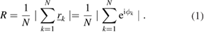
Clearly, if R = 1 the temporal phases are completely aligned. An estimate of the p-value under the null hypothesis that the vectors are uniformly distributed around the circle is given by [44]:
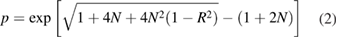
so that a small value of p indicates significant departure from uniformity, i.e. the null hypothesis can be rejected with 95% confidence for p < 0.05.
Figures 8–10 plots histograms of the instantaneous phases of the vertical position stabilization control coil current for all the ELMs that occur for both the signals of the current in the upper ( ) and lower coils (
 ). These histograms are plotted for the time interval of self-entrained dynamics t = 4.2 s to 5 s, and for comparison, time intervals of the same duration before (t = 3.2 s to 4 s) and after (t = 5.2 s to 6 s). As above, we have identified the ELM times (tR, upper panels) from the sharp rise in the ELM monitor signal and a time just before the ELM (tB, lower panels). We can see that the values of the control system coil current instantaneous phases at the times tB just before the onset of each of the ELMs, are strongly aligned, they are bunched around zero. This is also the case for the values of the control system coil current instantaneous phases at the later times tR, however at tR the control system may already be responding to the ELM onset. The fact that we see a high degree of phase alignment at both these times tB and tR confirms that this phase alignment does not simply reflect that response of the control system that occurs after the ELM has begun. The plots discriminate all ELMs (purple bars) from small ELMs (green bars overplotted) and this confirms the result that can be seen by inspection of figures 4 and 5, that large and small ELMs occur when the vertical position control system current are at phases ∼
 apart, that is, at opposite (+ve and −ve) excursions in the signal. The Rayleigh test statistics for all ELMs and for large ELMs only, respectively are:
  and 0.71;
  and 0.69;
  and 0.61;
  and 0.62. When both large and small ELMs are taken as a single population the phases are not random (p < 10−5 for all these populations) but a clear statistical discrimination requires identifying the large and small ELMs. There is thus a strong phase bunching or alignment of the large ELMs, with
  for the upper control coil current (
 ) and
) and  for the lower coils (
 ). The upper and lower control current signals are roughly in antiphase and there is a corresponding shift of ∼
 between these signals in the phases around which bunching occurs. We can compare this to some time intervals before and after that in which synchronization is found. These histograms are shown in figures 9 and 10. In both these intervals, small ELMs are seen at all phases and in the interval after synchronization t = 5.2 s to 6 s almost all the ELMs are small. In the interval before synchronization t = 3.2 s to 4 s there are both large and small ELMs and although the large ELMs are not randomly distributed in phase the p-value does not clearly reject this null hypothesis.

Figure 8. Histograms of instantaneous phases of the signal of the current in the upper ( ) and lower (
 ) vertical position control system coils at the ELM occurrence times (tR, upper panels) and just before (tB, lower panels). The histograms are for all ELMs that occur in the time interval of self-entrained dynamics t = 4.2 s to 5 s in plasma 30411. Purple bars are first plotted for all ELMs, then overplotted in green are bars for small ELMs only.
Download figure:
Standard image High-resolution image
Figure 9. Histograms of instantaneous phases of the signal of the current in the upper ( ) and lower (
 ) vertical position control system coils at the ELM occurrence times (tR, upper panels) and just before (tB, lower panels). The histograms are for all ELMs that occur in a time interval before self-entrained dynamics is seen, t = 3.2 s to 4 s in plasma 30411. Purple bars indicate all ELMs and overplotted in green are bars for small ELMs only.
Download figure:
Standard image High-resolution image
Figure 10. Histograms of instantaneous phases of the signal of the current in the upper ( ) and lower (
 ) vertical position control system coils at the ELM occurrence times (tR, upper panels) and just before (tB, lower panels). The histograms are for all ELMs that occur in a time interval after self-entrained dynamics is seen, t = 5.2 s to 6 s in plasma 30411. Purple bars indicate all ELMs and overplotted in green are bars for small ELMs only.
Download figure:
Standard image High-resolution imageWe can directly visualize any correlation between ELM size and control coil current ( ) phase by plotting plasma edge inward movement
  versus
  and this is shown as scatter plots in figure 11. Again, in the interval of synchronous dynamics (mid panel) large ELMs are clustered approximately within
  where there are few small ELMs. This is in contrast to the intervals before (top panel) and after (bottom panel) synchronous dynamics is seen. In the interval before, both large and small ELMs occur at all phases and in the interval after, almost all ELMs are small and again occur over a broad range of phases. For the intervals of the same duration, 0.8 s before, and after the interval t = 4.2–5 s of self-entrained dynamics, the ELMs do not readily separate into two populations (large and small) as they do when synchronous dynamics is occurring.

Figure 11. ELM correlated inward movement of the edge  is plotted versus the analytic phase (
 ) of the upper vertical position control system at the time just before each ELM tB for all of the ELMs that occur in each of three 0.8 s time intervals. The intervals are at times before (top panel), during (mid panel) and after (bottom panel) the interval of self-entrained dynamics. The threshold
  (grey line) is again used to distinguish small and large ELMs.
Download figure:
Standard image High-resolution imageELM size is known to correlate with waiting time, or inter- ELM time interval, and we plot waiting time versus control coil current phase ( ) in figure 12, where the waiting time of the kth ELM is
  . Longer waiting times tend to correlate with an
  phase just before the ELM occurrence time within
  , however shorter waiting times correspond to both small and large ELMs and can be found at all phase values.

Figure 12. ELM waiting time  is plotted versus the analytic phase (
 ) of the upper vertical position control system at the time just before each ELM tB for all of the ELMs that occur in the interval t = 4.2–5 s of self-entrained dynamics. The threshold
  is used to distinguish small (red circles) and large (blue circles) ELMs.
Download figure:
Standard image High-resolution image3.2. Control system vertical position stabilization coil current ordering of ELM cycle
We will finally plot the ELM cycle of dynamics directly from the data by plotting a variable that tracks the overall ELM cycle as function of the control system vertical position control coil current and its instantaneous temporal phase. A natural variable to track the ELM cycle is the total plasma MHD energy WMHD, but as discussed above (see figure 2 and accompanying discussion) the times tB and tF just before and just after the ELM, that are identified from the ELM monitor signal, are more clearly identifiable in Rout. Note that the choice of Rout as a system variable is not unique, one could use one of the other global plasma position variables obtained from high time resolution equilibrium reconstruction or fast parameterization, provided that it adequately resolves the ELM cycle dynamics. For example, the z position of the geometric axis, Zgeo, is of a similar amplitude to Rout and can from figure 2 also be seen to also track the ELM cycle.
The synchronized or self-entrained dynamics of control system and plasma is shown in figures 13 and 14. In figure 13 we plot the mean subtracted location of the plasma outer edge  and of the total plasma MHD energy
  versus the (mean subtracted) current in the control system field coils
  for the interval t = 4.2–5 s of self-entrained dynamics. The signal values just before each ELM, at time tB, are again plotted with blue circles for the large ELMs and red circles for small ELMs. On these plots the system executes a cycle with a crash (a) with fast inward motion of the edge and drop in energy, followed by a recovery (b) with little change in energy, and outward movement of the plasma edge then (c) build up with plasma edge roughly constant whilst the MHD energy increases. The system is at its largest edge excursion and energy just before each large ELM occurs (blue circles) when the (mean subtracted) vertical position stabilization control coil current is in the negative part of its oscillation. The smaller ELMs are more scattered but almost all occur when the vertical position stabilization control coil current is in the positive part of its oscillation. This is in contrast to what one would expect from a scenario in which roughly periodic ELMs with a random jitter in arrival times were simply coincident with a roughly periodic oscillation in the vertical position control coil current; in that case large and small ELMs would have equal likelihood of appearing at either the positive or negative excursion of the control system signal. Instead, in this interval of the dynamics we find that the vertical position stabilization control coil current phase discriminates between the larger, and smaller ELMs.

Figure 13. Mean subtracted location of the plasma outer edge  and of the total plasma MHD energy
  plotted versus the (mean subtracted) current in the control system field coils
  for the entire interval t = 4.2–5 s of self-entrained dynamics. All ELMs that occur within the interval are plotted and the threshold
  is used to distinguish small (red circles) and large (blue circles) ELMs which are plotted at the time tB just before each ELM. Grey dots indicate the full timeseries and a single short interval of roughly one cycle is indicated with the black solid line. The ELM crashes (a), recovery (b) and build up (c) are indicated with arrows.
Download figure:
Standard image High-resolution image
Figure 14. Mean subtracted location of the plasma outer edge  and of the total plasma MHD energy
  plotted versus the phase of the (mean subtracted) current in the control system field coils
  for the entire interval t = 4.2–5 s of self-entrained dynamics. All ELMs that occur within the interval are plotted and the threshold
  is used to distinguish small (red circles) and large (blue circles) ELMs which are plotted at the time tB just before each ELM. Grey dots indicate the full timeseries and a single short interval of roughly one cycle is indicated with the black solid line.
Download figure:
Standard image High-resolution image
The control system field coil current ( ) temporal phase orders this global plasma dynamics as shown in figure 14 which plots mean subtracted location of the plasma outer edge
  and of the total plasma MHD energy
  versus
  instantaneous phase, increasing time is then increasing phase on these plots. The ELM crashes occur close to
  and again, the
  phases of the large ELMs tend to be clustered about zero. The build up to the ELM is just before this, within
  and the recovery begins just after. The small ELMs (red) occur from the end of the recovery phase and throughout the build up phase.
4. Discussion
We have identified an interval of natural ELMing in which current in the control system vertical position stabilization field coils continually oscillates in a manner which is synchronized with oscillations in the plasma edge position and total MHD energy. Importantly, there is a one-to-one correlation between these oscillations and ELM occurrence; ELMs occur preferentially when oscillations in the current in the control system vertical position stabilization field coils are at a specific temporal phase. Large and small ELMs tend to occur at opposite phases or excursions of the current in the vertical position control field coils.
The control system vertical position stabilization field coils are essential to the active stabilization of the plasma. The control system takes as its inputs multiple plasma properties, including global plasma shape, current, position and velocity inferred from plasma equilibria calculated in real time. Examples of these are the signals analysed here: the plasma stored energy WMHD and the edge position Rout. One of control system outputs is to apply voltages to the vertical stabilization field coils. This modifies the current in the field coils, generating inductive magnetic fields that react back on the plasma.
Large scale perturbations in plasma position can be driven externally by applying magnetic kicks through the same control system vertical position stabilization field coils, and these have been shown to entrain ELMs to the driving frequency of the kicks [20–23]. Evidence that this is indeed entrainment [24] is that the amplitude of the driving force needed to achieve entrainment is at a minimum when the driving frequency matches that of ELMs that are found to occur naturally in the absence of an externally applied driving [23]. The entrained ELMs correlate with vertical displacement of the plasma that is induced by the applied magnetic kicks. ELM entrainment is also sensitive to conditions at the plasma edge. In experiments on AUG-C with partial carbon wall coverage [21] it was found that the plasma displacement associated with natural ELMs (vertical displacement z ∼ 5–7 mm) defined a critical threshold which needed to be exceeded in order for ELMs to become entrained to the external driving frequency. Imposing a significantly smaller z shows no effect, on either plasma motion or ELM behaviour. With z in the range 6–10 mm, incomplete locking was achieved, between the observed ELM frequency and the driving frequency. At  mm almost immediate locking was achieved and maintained [21]. However, when these experiments were repeated in AUG-W following changeover to an ITER-like, all metal wall [15], the ELM frequency did not lock to the driving frequency and entrainment could not be achieved even at large vertical peak-to-peak amplitudes
  mm.
mm.
ELM entrainment, in the sense discussed above, then may be understood as ELMs being generated as a response to the applied magnetic kicks and resulting plasma displacements. Following each ELM, the active control system will also adjust to stabilize the plasma but any effect on the plasma state relevant to ELMing is considered to be negligibly small compared to that imposed by the applied kicks. The applied perturbations are sufficiently large to overcome any displacements that would occur due to natural ELMing.
Here we propose that natural ELMing can occur via self-entrainment between the active control system and the plasma. In this case there are no externally applied magnetic kicks. Instead, changes in the plasma state, leading to an ELM, emerge from the dynamics of the nonlinear active feedback between the active control system and the plasma. The active control system is constantly adjusting the plasma position and shape, both in response to an ELM, and in response to other modes and instabilities that can occur between one ELM and the next. In plasma 30411 analysed here there are no externally applied magnetic kicks; the current in the control system vertical stabilization field coils arises solely from the feedback between the control system and plasma. Plasma 30411 was an AUG-W experiment and the vertical displacement associated with the ELMs is: (i)  mm in the synchronized interval t = 4.2–5 s; (ii)
  mm in the interval before it, t = 3.2–4.0 s and (iii)
  mm in the interval after, t = 5.2–6 s. Phase synchronous, or self-entrained ELM dynamics is thus associated with displacements that are at least 50% below the threshold required for entrained (externally kicked) ELMing. This is consistent with a natural ELMing process that involves phase synchronous, self-entrained dynamics that can occur even when the vertical position control coil current amplitude is small, as we have found previously on JET [27–31]. It is distinct from entrainment which requires a large amplitude driving of the ELMs by externally applied magnetic kicks.
This implies that any physical model for self-entrained natural ELMing must include the coupling and non-linear feedback between the plasma and the active control system. One possibility is resonance between the control system and natural ELMing but this would require quite specific conditions, that is, a frequency matching between the natural ELMs and a resonant frequency of the control system and its feedback timescales. In contrast, phase synchronization can occur over a broader range of conditions [24] and can generate a richer range of phenomenology. Within the framework of phase synchronization, the control system phase provides a parameter that orders the observed ELM properties as we have found here, with large and small ELMs occurring at opposite phases or excursions of the current in the control system vertical stabilization field coils. It may thus provide a useful parameter for ELM classification.
Future work is needed to establish the full range of conditions under which synchronization can occur. Examples of it have been found in other AUG plasmas [32], also [46] under different conditions (plasma 30792,  MA,
MA,  T and
T and  m−3) and with different heating power (NBI heating
  MW and
  MW), to that of plasma 30411 discussed here. The vertical displacement is larger in the interval of self-entrainment as compared to earlier and later times. This may be a consequence of self-entrained dynamics, where there is a positive feedback between the vertical position control coil current and global plasma dynamics which in turn enhances the vertical motion. Since there is feedback both from control system to plasma and from plasma to control system, it has the potential to be self-regulating so that it keeps the vertical displacement just below that required for externally driven entrainment. Global plasma dynamics plays a role in both externally driven, entrained ELMs and in naturally occurring self-entrained ELMs. In either case, the ELM finally occurs via instability at the plasma edge. Changing from AUG-C to AUG-W modified the threshold for externally driven, entrained ELMs. Changes in conditions at the edge may then also affect whether fully synchronous, self-entrained natural ELMing can occur. In the plasma studied here, self-entrainment stops when Nitrogen seeding is switched on. Intriguingly, on JET, natural compound ELMs were more frequently observed with the carbon wall than with the more recent ITER-like metal wall. These compound ELMs [39] are trains of highly time-regular small ELMs that follow directly from a single large ELM, reminiscent of ELMing via fully synchronized, self-entrained dynamics discussed here.
5. Conclusions
Time domain time series analysis in an ASDEX Upgrade plasma has identified an interval of natural ELMing in which current in the control system vertical position stabilization field coils continually oscillates, and is synchronized with oscillations in the plasma edge position and total MHD energy. In this synchronous, or self-entrained state there is a one-to-one correlation between oscillations in the vertical position control coil current and ELM occurrence; ELMs occur preferentially when oscillations in the current in the control system vertical stabilization field coils are at a specific temporal phase. This interval of synchronized ELMing switches on with an increase in applied neutral beam injection (NBI) heating and switches off at the start of nitrogen seeding, suggesting that this may be a controllable phenomenon. Examples of it have been found in other AUG plasmas [32, 46] under different conditions. Here we have found a feature of synchronous dynamics not reported previously: the amplitude of the inward contraction of the plasma edge during an ELM is used to identify two populations, small and large ELMs, and these tend to occur at the opposite excursions of the control system current. In this interval of self-entrained dynamics, the instantaneous phase of the control system vertical stabilization field coil current correlates with indicators of ELM size: larger inward movements of the edge and longer ELM waiting times occur around a specific phase. Our results suggests that during intervals of synchronous dynamics the phase of the control system can provide a useful co-ordinate, or 'clock' to quantify the ELM cycle; the same phase relationship will persist even if the ELM frequency is drifting. It may assist in understanding and perhaps simplifying the classification of ELM types.
It is also well established that ELMs can be entrained to the frequency of applied global magnetic perturbations. These perturbations are delivered to the plasma using the vertical control system stabilization field coil currents. These field coils are also part of an active control system that is required to maintain the plasma in a steady state. We have identified that, in this AUG plasma, ELMs naturally occur around a specific temporal phase in the current in these field coils, in the absence of any perturbation that is purposely externally applied. This suggests that control system-plasma feedback can be come fully synchronized [24, 42, 43] with these synchronous oscillations coinciding with the occurrence times of all the natural ELMs that occur within the time interval of self-entrainment. This self-entrainment can be a significant part of the natural ELMing process in the plasma studied. Control system-plasma feedback thus becomes an essential component for integration into future models of natural ELM dynamics. High time resolution solutions for the control coil currents and magnetic field perturbations applied dynamically to the plasma could usefully be included in future implementations of fast equilibrium solvers in order to further advance our understanding of natural ELMing. In this self-entrained dynamics, the ELM occurrence times and energies both become more predictable.
Acknowledgments
This work has been carried out within the framework of the EUROfusion Consortium and has received funding from the Euratom research and training programme 2014–2018 under grant agreement No 633053 and from the RCUK Energy Programme [grant number EP/P012450/1]. The views and opinions expressed herein do not necessarily reflect those of the European Commission. S.C.C acknowledges a Fulbright-Lloyd's of London Scholarship and AFOSR grant FA9550-17-1-0054.