
Abstract
Objective. Non-invasive brain stimulation has been promoted to facilitate neuromodulation in treating neurological diseases. Recently, high-definition (HD) transcranial electrical stimulation and a novel electrical waveform combining a direct current (DC) and theta burst stimulation (TBS)-like protocol were proposed and demonstrated high potential to enhance neuroplastic effects in a more-efficient manner. In this study, we designed a novel HD transcranial burst electrostimulation device and to preliminarily examined its therapeutic potential in neurorehabilitation. Approach. A prototype of the transcranial burst electrostimulation device was developed, which can flexibly output a waveform that combined a DC and TBS-like protocol and can equally distribute the current into 4 × 1 HD electrical stimulation by automatic impedance adjustments. The safety and accuracy of the device were then validated in a series of in vitro experiments. Finally, a pilot clinical trial was conducted to assess its clinical safety and therapeutic potential on upper-extremity rehabilitation in six patients with chronic stroke, where patients received either active or sham HD transcranial burst electrostimulation combined with occupational therapy three times per week for four weeks. Main results. The prototype was tested, and it was found to comply with all safety requirements. The output parameters were accurate and met the clinical study needs. The pilot clinical study demonstrated that the active HD transcranial burst electrostimulation group had greater improvement in voluntary motor function and coordination of the upper extremity than the sham control group. Additionally, no severe adverse events were noted, but slight skin redness under the stimulus electrode immediately after stimulation was seen. Conclusions. The results demonstrated the feasibility of incorporating the HD electrical DC and TBS-like protocol in our device; and the novel neuromodulatory device produced positive neurorehabilitation outcomes in a safe fashion, which could be the basis for the future clinical implementation for treating neurological diseases.
Trial registration: ClinicalTrials.gov Identifier: NCT04278105. Registered on 20 February 2020.
Export citation and abstract BibTeX RIS

Original content from this work may be used under the terms of the Creative Commons Attribution 4.0 license. Any further distribution of this work must maintain attribution to the author(s) and the title of the work, journal citation and DOI.
1. Introduction
NIBS protocols, such as tDCS and rTMS, have been extensively investigated as promising neuromodulatory techniques, which are beginning to be used clinically to modulate cortical excitability. tDCS polarizes the resting membrane potential by subthreshold stimulation and modulates ongoing spontaneous neuronal firing [1], while rTMS depolarizes neurons by suprathreshold stimulation and induces neuronal firing [2]. Although tDCS and rTMS underlie different neuromodulatory mechanisms, both of them have been demonstrated to induce long-lasting changes in cortical excitability that can enhance mental and physical functions after a short period of stimulation [3, 4]. However, rTMS is much more complicated, costlier, and bulkier to deliver to patients than tDCS and may be associated with more risks, particularly the potential for causing seizures [5, 6]. Moreover, tDCS is more portable and has the potential for simultaneous use with rehabilitation or task-specific training as a means to enhance neuroplasticity.
Several flaws have restricted the clinical effects of tDCS, although a large number of clinical trials have demonstrated modest effects of tDCS on neuromodulation and functional improvements [7–9]. Conventional tDCS can only provide a DC waveform, which may sacrifice flexibility and tailoring of stimulation parameters for different patient populations, thus diminishing the therapeutic effects. Moreover, conventional tDCS employs rectangular saline-soaked sponge pads (commonly 25 ∼ 35 cm2) [10] and induces diffuse distributions of current flow in widespread brain areas, where the largest electrical field strength might not occur directly underneath the electrodes [11–13]. Thus, improvements in the output waveform and montage are needed to enlarge the treatment effects of conventional tDCS.
A novel electrical waveform combining DC with TBS-like waveforms was proposed to enhance the effectiveness and efficiency of transcranial electrical stimulation on brain neuroplasticity [14, 15]. TBS, a patterned form of rTMS, is a revolutionary form of brain stimulation that mimics the natural rhythms of brain neurons [16]. TBS can be applied using a continuous protocol (cTBS) to induce long-term depression-like cortical plasticity or using an intermittent protocol (iTBS) to induce long-term potential-like cortical plasticity [17]. TBS was demonstrated to more efficiently produce relatively strong, long-term changes in the excitability of cortical circuits after only a few minutes of simulation [16, 17]. Furthermore, combining DC with intermittent TBS-like waveforms showed a stronger neuroplastic effect than the conventional DC waveform in our animal study [14], which has promising therapeutic potential for human neurological diseases such as stroke and psychiatric disorders.
A diminished electrode size was shown to reduce the affected cortical area size, and thus increase focalization of transcranial electrical stimulation [11, 18]. HD electrode arrays were developed to limit the spread of current flow outside of the target area and thus achieve a more-localized electrical field distribution [11, 19, 20]. The electrode montage exhibits a 4 × 1 ring configuration, with a central active electrode surrounded by four return electrodes, which can produce a more-focalized transcranial current confined within the target cortical area of interest [11]. Recent studies demonstrated that HD can induce greater cortical excitability and a longer-lasting after-effect [21, 22].
The potential of DC combined with TBS-like waveforms may produce promising therapeutic effects with transcranial electrical stimulation; however, few studies have further delivered this special waveform underlying an HD electrode montage. Thus, the aim of this study was to design and develop a sophisticated transcranial burst electrostimulation device with HD electrodes for application in clinical neurorehabilitation. In this proof-of-concept study, a novel HD transcranial burst electrostimulation device was first implemented, which integrated three printed circuit boards, including circuits of a DC generator, a TBS current generator, and impedance adjustment. A series of in vitro experiments was subsequently conducted to validate the accuracy of the current output and impendence adjustment function of the prototype device. Finally, a pilot clinical trial was conducted to preliminarily determine its feasibility, safety, and therapeutic potential in patients with chronic stroke.
2. Methods
2.1. Design of the HD transcranial burst electrostimulator system
In this study, a prototype of an HD brain stimulation system was designed, as shown in figure 1. The overall structure of the system was composed of three major components, including: (a) a main stimulation body, comprising a power supply module, MCU module, and waveform generation module, housed in a double-insulated plastic box; (b) a set of applied-interface parts, consisting of a head cap, wires, and HD electrode montage; and (c) controlling software, developed by MATLAB software and installed on a laptop PC, which was capable of setting the stimulation current and period, and other parameters.
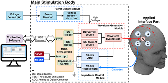
Figure 1. Overall structure of the high-definition transcranial burst electrostimulator. The system comprised three major components, including a main stimulation body, a set of applied-interface parts, and controlling software. A, anodic electrode; C, cathodic electrode.
Download figure:
Standard image High-resolution imageInside the main stimulation body, the MCU module was established by a commercial Arduino Mega 2560 board, which was based on an ATmega microchip and equipped with functions and components needed to support the microcontroller. The MCU module is the core of the system and was utilized to control the waveform generator circuits and impedance adjustment circuits. The user can set up the stimulation parameters using the controlling software on a laptop PC, and then the selected parameters are sent to the main stimulation body through a USB port of the MCU module. For electrical safety, we installed an isolated USB transceiver (LTM2284, Analog Devices, Wilmington, MA, USA) between the MCU module and the laptop PC.
The stimulator was powered by a 5 V DC source, for which the rated current was 300 mA. The power source was well isolated by the power isolation module for safety and stability issues. To provide sufficient voltage to the output stage, a 5 ∼ 36 V voltage booster circuit with XL6009 (by Kylinchip, Shanghai, China) was designed.
Figure 2 illustrates the detailed electrical circuits of the waveform generator module. The waveform generator module mainly consists of two subsets of current generator circuits, i.e. DC and TBS circuits, as shown in figure 2(a). Both circuits can output an electrical current ranging from 0 to 2 mA (0.25 mA/step) using an adjustable current source unit (LM334, Texas Instruments, Dallas, TX, USA) and was also controlled by eight single-pole/single-throw switches (ADG5412, Analog Devices) to choose specific resistors. The DC and TBS output triggers used GPIO ports that were controlled by ISR events to control the timing of waveform generation with no notable delays. Thus, the waveform generator module can produce a TBS-like waveform that consists of three pulses per burst output, with a 0.5 ms pulse duration over 20 ms, and which repeats every 200 ms (i.e. 5 Hz each burst), as shown in figure 2(b). To avoid discomfort caused by a sudden increase in the stimulation current, a 5 s ramp-up and ramp-down waveform current was set at the beginning and end of brain stimulation.
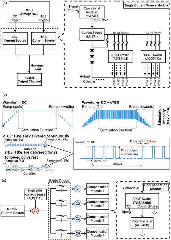
Figure 2. Detailed circuit design for the waveform generator and impedance modules in the main stimulation body. (a) The waveform generator module integrated the electrical circuits of direct current (DC) and theta burst stimulation (TBS) current generators. (b) Profile of the TBS combined with DC waveform output from the waveform generator module. (c) An impedance adjustment circuit designed to evenly distribute the stimulation current from an anodic (A) to four cathodic electrodes (C1 ∼ C4).
Download figure:
Standard image High-resolution imageThe impedance adjustment circuit was designed to ensure that the current is evenly distributed from an anodic to four cathodic electrodes, as shown in figure 2(c). Before stimulation, the impedance was measured with an adjustable current source unit (LM334) which generates the 0.1 mA current that individually passes through each anode-cathode pair. Subsequently, the analog-to-digital converter (ADS1115, Texas Instruments) detects the voltage between each anode-cathode pair to measure the resistance according to Ohm's law. The highest resistance value was determined as the baseline to compensate for the rest of the current pathway, by switching the SP3T switches (TS5A3359, Texas Instruments) to closer potentiometers (AD8400, Analog Devices). For safety considerations, the maximal resistance for system operation was set to 50 kΩ.
The electrostimulator was designed to flexibly output various stimulation waveform protocols by setting the graphic user interface of the controlling software, such as DC, DC combined with iTBS, and DC combined with cTBS waveforms. Figure 3 illustrates the flowchart of software working items and the user interface for the manual operation of the transcranial burst stimulation device. The stimulation mode is selected as the first step after the stimulation electrodes are applied to the scalp (figure 3(a)). Then, stimulation parameters, such as the duration and current intensity, are selected.
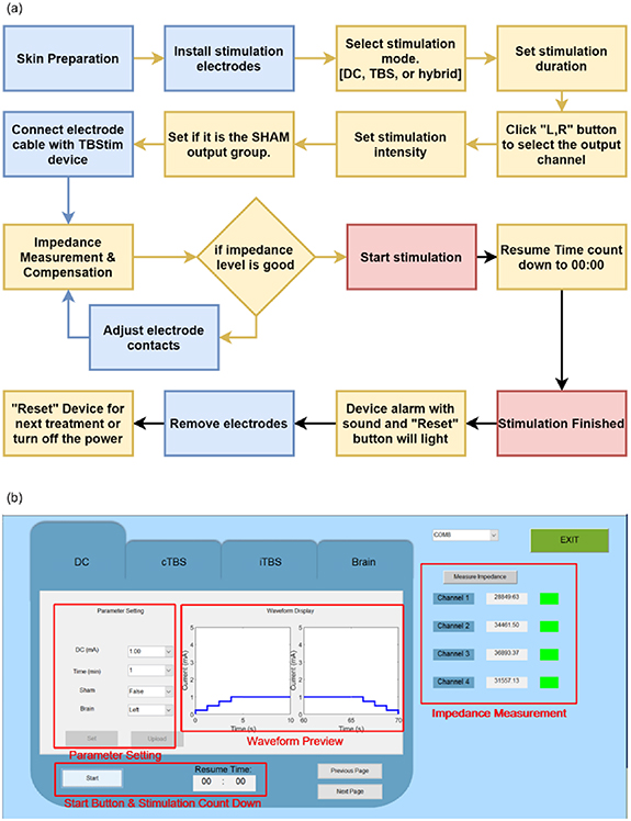
Figure 3. Controlling software for setting the stimulation waveform protocols. (a) Flow chart of software operation in the system. (b) Graphic user interface for selecting the stimulation parameters.
Download figure:
Standard image High-resolution imageThe duration of stimulation can be set up to 30 min with an increment of 1 min. The impedance between the anode and cathodes is then measured and adjusted accordingly if the measured impedance is smaller than the default value (<50 kΩ), otherwise the device will be inactive and wait for confirmation of adequate electrode-tissue contact. After confirming all the parameters, the 'Set' and 'Upload' buttons are pressed on the user-device interface, to upload all parameters to the hardware and communicate with the firmware, as shown in figure 3(b).
After finishing the setting of all the treatment parameters, the user needs to decide whether the treatment belongs to 'true' or 'sham'. The function of the sham model allows an investigator to perform a blinded study on all subjects that can eliminate the placebo effect. Under the sham model, the program will begin with a 5 s ramp-up to elevate the current to the setting, and immediately be followed by a 5 s ramp-down to diminish the current to zero. At the end of the program, symmetrical ramp-up and -down are applied again. This design will create sensational stimulation at the beginning and the end of the program to treat a subject with a placebo. No current is delivered in the middle of the program under the sham model.
2.2. Computational simulation of the current distribution in the brain cortex
In order to validate the focalized performance of the special current waveform under an HD montage of the brain, a software simulation experiment was conducted to analyze the distribution of current flow and the electrical field. We utilized an open-source computational modeling tool developed by Parra Lab at City College of New York, namely an ROAST electric simulation (www.parralab.org/roast/) to generate a 3D rendering of the E-field distribution [23, 24]. The ROAST module runs on MATLAB, and calls open-source function SPM12 [25] to segment magnetic resonance imaging (MRI) images, iso2mesh [26] to generate a finite element model, and getDP [27] to resolve the finite element model. The MRI structural model is a version of the International Consortium for Brain Mapping (ICBM) Average Brain—an average of 152 T1-weighted MRI scans, linearly and non-linearly (six iterations) transformed to form a symmetrical model in the Talairach space (http://nist.mni.mcgill.ca/?p=858). The parameters were set to default except for the electrode style and positions.
To compare the focalized performance of the current distribution over the target cortex location between the traditional tDCS sponge electrode and the HD tDCS montage, the simulation current parameters were set to defaults of the simulation software, but the electrode style and target position differed. The simulation target position was set to the left M1. The conventional pad electrodes (50 × 30 mm) set C3 as the anode and C4 as the cathode. The HD montage with small electrodes (6 mm in diameter) set C3 as the anode and Cz, F3, T7, and P3 as the cathodes.
2.3. Validation of system performance
After implementing the prototype electrostimulator system, the accuracy of the current output and impendence adjustment performance were both validated in vitro. To validate the output current accuracy, the accuracy was calculated by the current error percentage as shown in equation (1). To validate the impendency performance, a total 4 kΩ resistor circuit with four cathode channels in parallel was designed, and each channel was under a 1 kΩ equivalent resistance. Then the impedance was measured by the voltage value via an oscilloscope between an anode–cathode pair under various current outputs, on the basis of Ohm's law:

2.4. Pilot clinical trial in stroke cases
2.4.1. Subject recruitment
A pilot clinical trial was conducted to determine the performance of our prototype device on subjects with chronic stroke. The pilot study was conducted at Taipei Medical University Hospital (Taipei, Taiwan) and was approved by its institutional review board (IRB no.: N201909051). Six subjects with chronic stroke were recruited. The inclusion criteria were as follows: (a) ⩾20 years of age; (b) 6 months to 5 years after a stroke; (c) a Brunnstrom stage for the UE of III to V; and (d) the absence of excessive muscle tone in the affected limb (1 ∼ 3 on the Modified Ashworth Scale). Subjects with contraindications for transcranial electrical stimulation, those with contracture or inflammation of the upper extremities, and those with severe cognitive or psychiatric disorders were excluded. All subjects were independently evaluated for eligibility by a physician, and informed consent was signed in person. This trial was registered under ClinicalTrials.gov ID no. NCT04278105.
2.4.2. Experimental procedures
Three subjects were assigned to the experimental group and the remaining to the sham control group. All subjects were blinded to their group assignment. Both groups received 20 min of active/sham HD transcranial electrical stimulation combined with 30 min of UE rehabilitation of the affected side each time, three times a week, lasting for four weeks. HD transcranial electrical stimulation was applied using a 4 × 1 ring electrode configuration. The anodal electrode was placed on the ipsilesional M1 (C3/C4), and the remaining four cathodal electrodes were placed over Cz, F3, T7, and P3 on the left hemisphere or over Cz, F4, T8, and P4 on the right hemisphere. Active electrical stimulation was applied at an intensity of 1.0 mA of DC stimulation combined with an intensity of 1.0 mA of iTBS. Sham electrical stimulation consisted of a 5 s ramp-up immediately followed by a 5 s ramp-down, no current in the middle 19 min 40 s, and a ramp-up and ramp-down period during the final 10 s. UE rehabilitation programs were selected and graded by occupational therapists in accordance with each patient's UE function and specific aims of activities of daily living.
A week before treatment initiation (baseline), clinical and demographic characteristics of each patient were collected. In both groups, functional outcomes were measured at the baseline and a week after 12 therapeutic sessions had been completed (post-treatment) by a researcher aware of which subjects had received real treatment.
2.4.3. Outcome measures
Outcome measures included the FMA-UE and the FTN test. The FMA-UE assesses voluntary movement of the UE [28]. Each movement is estimated on a 3-point scale (0, 1, or 2). The total score of the FMA-UE is 66, and a higher score indicates that a patient has better movement ability. The FMA-UE has sound validity and responsiveness [29]. The FTN test assesses coordination of UE movement. The number of complete nose-target movements during a 20 s period was recorded.
Adverse effects of the electrical stimulation were monitored by asking patients the incidence and severity of the following symptoms that they experienced after each intervention session: headaches, neck pain, scalp pain, tingling, itching, burning sensation, skin redness, sleepiness, difficulty concentrating, altered mood, or any other problems.
3. Results
3.1. Specifications of HD transcranial burst electrostimulator
We successfully implemented a prototype HD transcranial burst electrostimulator system, as shown in figure 4. The system comprised controlling software, a main stimulation body, and a set of applied interfaces (wires, electrodes, and head cap), as shown in figure 4(a). In the main stimulation body, a power supply module (XL6009), an MCU Module (Arduino Mega 2560), and several circuits for waveform generation were integrated on a 15.2 (L) × 21.5 cm (W) rectangular double-layer printed circuit board, as shown in figure 4(b). The main board was connected to a USB isolation board (LTM2284, Analog Devices) and then linked to the I/O port of the plastic box. All printed wire boards were housed in a 25 × 18 × 7.5 cm plastic enclosure, as depicted in figure 4(c). Detailed system specifications are tabulated in table 1.
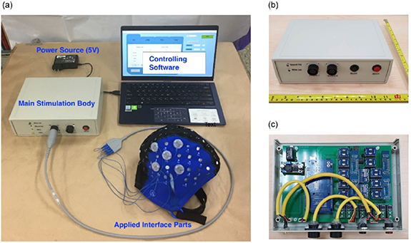
Figure 4. Prototype high-definition transcranial burst electrostimulator system (a) the entire system of the high-definition transcranial burst electrostimulator device. (b) Exterior view of the main unit (stimulator), and (c) internal view of the main unit.
Download figure:
Standard image High-resolution imageTable 1. Specifications of the electrostimulator system.
| Hardware specifications | |
|---|---|
| Number of channels: | 1 anode + 4 cathodes |
| Type: | tDCS, TBS and customized waveform |
| Sham mode: | Available |
| Adjustable duration | 1 ∼ 30 min at 1 min resolution |
| Stimulation output current | 0.00 ∼ 2.00 mA |
| Output current resolution | 0.25 mA |
| Output current accuracy | <2% ∼ 5% |
| Data in | USB type B, 5 V |
| DC in | 5 V, 0.3 A |
| Dimension of the main stimulation body | 20 × 25 × 7.5 cm (L × W × H) |
| Weight of the main stimulation body | 250 g |
| Power supply | Medical grade, output 5 V DC, 3 A |
| Electrode specifications | |
| Electrode size | 1.2 cm in diameter |
| Cap layout | International 10-10 system |
tDCS, transcranial direct current (DC) stimulation; TBS, theta burst stimulation.
3.2. Computational simulation of the current distribution in the brain cortex
According to the results of the ROAST [23, 24] software simulation to predict brain currents (figure 5), it was observed that the electric field was extensively distributed throughout the entire brain in the bilateral tDCS montage with conventional sponge electrodes, where the maximum current intensity (peak value) was largely spread in the area surrounding the sponge electrode position. Contrarily, results of the HD-montage with small electrodes, as shown in figure 5(b), show that the electric field distribution was relatively limited within a small circular range (3.5 cm diameter for our system), and also the peak of the current (electric field) was just below the central electrode. We further analyzed the voxel influence range of the maximum voltage intensity. Compared to conventional sponge electrodes, the coverage of the HD-montage at 80% of the maximum voltage intensity was reduced to 1/4 (2.7% vs 10.8% of total voxels), and the coverage at 60% of the maximum voltage intensity was reduced to 1/13. (4.3% vs 32.6%). At 40% intensity of the maximum voltage intensity, it showed an even greater advantage of the HD-montage focusing effect, which was the difference of the effective area between the local and almost the entire brain (15.3% vs 76.2%). The simulation results suggested that the use of our high-precision electrode configuration could focalize the stimulation current over a smaller area compared to conventional sponge electrodes. For the recovery and enhancement of motor function, we only wanted to focus on the stimulation area in the motor function area cortex M1, which is more specific than the traditional electrode montage.
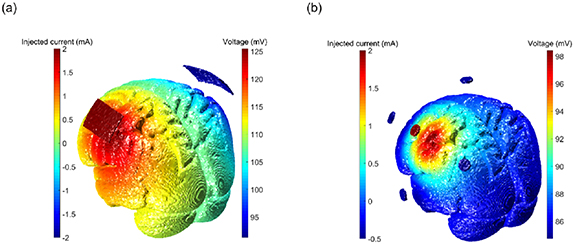
Figure 5. Computational simulation of the current distribution in the brain cortex using a finite element method. Simulation results of (a) conventional transcranial direct current stimulation (tDCS) sponge electrode exhibited a large current distribution area compared to that of (b) the 4 × 1 high-definition montage.
Download figure:
Standard image High-resolution image3.3. Validation of system performance
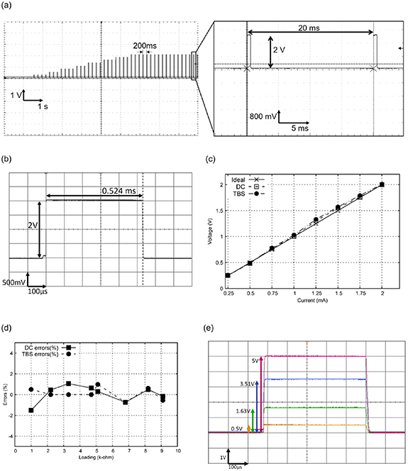
To validate the performance of the current output of our electrostimulator system, several in vitro electrical tests were conducted to confirm the accuracy and electrical safety of the device before conducting pilot clinical trials. Figure 6 shows outcomes of electrical safety testing, for which measurements were made with a digital oscilloscope (DSOX2004A, Keysight Technologies, Colorado Springs, CO, USA). Our results demonstrated that the device correctly delivered ramp-up amplitudes of TBS waveforms operated by the controlling software (figure 6(a)). There was no significant shape distortion of the basic square pulses, as shown in figure 6(b). The basic components of the TBS waveform were measured for current bursts repeated at 5 Hz (separated by 200 ms), each burst had three pulses of 50 Hz (separated by 20 ms), and the pulse width was fixed at 0.524 ms. Accuracies of the burst interval and pulse duration were up to 95%.
Figure 6. Outcomes of electrical safety testing of both the direct current (DC) and theta burst stimulation (TBS) waveforms. (a) The system correctly delivered ramp-up amplitudes of the TBS waveform. No significant waveform distortion of the square pluses was detected. (b) No significant shape distortion of the basic square pulses was observed in a single pulse of the TBS waveform. (c) Linear performance of the amplitude output of the DC and TBS waveforms under different current values with a 1 kΩ resistor. (d) Errors of the output potentials were measured under different loading resistors. (e) The current was equally distributed to each pair after compensation.
Download figure:
Standard image High-resolution image
The output accuracy of the current intensity is one of the key factors, which affects the electrical safety and therapeutic effects in clinical applications. Figure 6(c) shows the linear performance of the amplitude output of the DC and TBS waveforms when four anode and cathode pairs were all connected in parallel with the 4 kΩ resistors. Both the DC and TBS waveforms exhibited good linear characteristics when the current intensity output increased from 0.025 to 2 mA. General errors of the amplitude output for the DC and TBS waveforms were both <2%.
Since the contact quality of the electrode-scalp interface may affect the magnitude of the impedance value and subsequently produce an error in the output of current potential, we validated the error of the current potentials, with the output errors being measured by connecting different loading resistors. Our results revealed that the output errors of the DC and TBS waveforms were both <2% under loading resistors ranging 1 ∼ 10 kΩ, as shown in figure 6(d).
Finally, the impedance compensation function was further validated to confirm that the HD montage equally distributed the stimulation current to each anode–cathode pair when the electrode-tissue impedance changed. Our results demonstrated that potential drops of 0.5, 1.63, 3.51, and 5 V were measured when the resistor loading was set to 1, 3.3, 6.8, and 10 kΩ resistors, as shown in figure 6(e). Thus, our results indicated that the current was correctly distributed to each electrode pair.
3.4. Pilot clinical trial in stroke cases
Six subjects with chronic stroke were recruited for the study, three of whom were in the experimental group. Half of the subjects were men; half had been diagnosed with an ischemic stroke, and the other half had been diagnosed with an infarction. Table 2 gives the demographic data and stroke characteristics of subjects.
Table 2. Characteristics of subjects.
| Group and ID | Gender | Age (years) | Stroke chronicity (month) | Type of stroke | Affected side | UE Brunnstrom stage |
|---|---|---|---|---|---|---|
| TES group | ||||||
| TES 1 | M | 56 | 9.6 | Infarction | Left | V |
| TES 2 | M | 35 | 10.7 | Hemorrhage | Left | III |
| TES 3 | F | 52 | 21.4 | Hemorrhage | Left | III |
| Mean ± SD | 47.4 ± 11.2 | 13.9 ± 6.5 | ||||
| Sham group | ||||||
| Sham 1 | M | 51 | 30.1 | Infarction | Right | IV |
| Sham 2 | F | 83 | 12.6 | Infarction | Right | III |
| Sham 3 | F | 54 | 9.8 | Hemorrhage | Right | V |
| Mean ± SD | 62.7 ± 17.7 | 17.5 ± 11.0 |
UE, upper extremity; TES, transcranial electrical stimulation; SD, standard deviation.
Functional outcomes measured before and after four weeks of the therapeutic intervention are shown in table 3. For the UE motor function, the experimental group was compared to the control group and showed greater improvement in the FMA-UE (mean changes of 5.0 and 0.7, respectively). Mean changes in the scores of the FTN test were 5.3 in the experimental group and 0.7 in the control group, indicating that the experimental group had greater improvements in coordination of UE movements than the control group.
Table 3. Scores of each outcome measure at pre- and post-treatment.
| FMA-UE | FTN | |||||
|---|---|---|---|---|---|---|
| Group and ID | Pre | Post | Change | Pre | Post | Change |
| TES group | ||||||
| TES 1 | 62 | 66 | 4 | 50 | 56 | 6 |
| TES 2 | 32 | 36 | 4 | 13 | 21 | 8 |
| TES 3 | 38 | 45 | 7 | 9 | 11 | 2 |
| Mean change ± SD | 5.0 ± 1.7 | 5.3 ± 3.1 | ||||
| Sham group | ||||||
| Sham 1 | 59 | 58 | −1 | 23 | 26 | 3 |
| Sham 2 | 22 | 23 | 1 | 14 | 11 | −3 |
| Sham 3 | 48 | 50 | 2 | 10 | 12 | 2 |
| Mean change ± SD | 0.7 ± 1.5 | 0.7 ± 3.2 | ||||
FMA-UE, Fugl-Meyer Assessment of Upper Extremity; FTN, finger-to-nose test; TES, transcranial electrical stimulation; SD, standard deviation.
No severe adverse events were recorded over the 12 treatment sessions. Two subjects (TES 1 and TES 3) reported slight skin redness under the stimulus electrode at the end of several treatment sessions, which is a common physical response immediately after electrical therapy. The two subjects reported no other uncomfortable feeling after treatment.
4. Discussion
In the present study, we developed a transcranial TBS-like electrostimulator with an HD montage to reinforce the treatment effect of rehabilitation training. The device provides various combinations of waveforms outputs (DC, iTBS/cTBS, DC + iTBS/cTBS, and sham) with eight steps of amplitude resolution (0.25 ∼ 2 mA). The stimulator incorporates a set of impendence adjustment circuits to ensure that the electrical current passing through the four cathode leads has the exact same energy distribution. To the best of our knowledge, ours is the first study to develop and implement a non-invasive electrostimulator with a combination of DC and TBS waveforms for an HD montage that can provide focalized specialized stimulation with enhanced neuron modulation potential.
It is critical to ensure that the output potential and current are within limits. To prevent 'hazardous voltage' specified by the standard for electrical safety (IEC60601-1), we implemented an 'inherent single-fault tolerance' method, which limits the supply voltage to the current source chips (LM334). We verified the accuracy of the output current and waveform parameters using various resistors and an oscilloscope. Maximum errors were within 2% for the amplitude and 5% for the duration, which are considered acceptable based on IEC standards for general electrical stimulators (20%).
In the last decade, tDCS has been broadly used as a safe method of NIBS for neural modulation. A systematic review by Bikson et al indicated that the stimulation intensity of conventional DC for up to 40 min of 4 mA stimulation current with 7.2 C caused no significant brain injury [30]. Conventional protocols commonly use sponge electrodes with a size of 5 × 5 cm and a current density of 0.8 A m−2 when the output current is set to 2.0 mA. In our study, we reduced the electrode size of ring electrodes to 3.6 cm2 (2.4 cm in diameter) for HD stimulation, and the current density was approximately 7-times that of a conventional pad electrode. Liebetanz et al stated that brain lesions occurred at a threshold current density of 142.9 A m−2, and the current density for tDCS with 2 mA output should be far from the threshold [31]. Thus, our ring-electrode design for HD transcranial stimulation is still in accord with safety standards. Recent research by Chhatbar et al further demonstrated that a single session of tDCS with 4 mA intensity for a duration of 30 min was safe and tolerable in stroke subjects [32]. Moreover, if the pad electrodes were replaced by 1 × 4 HD-tDCS ring electrodes with 2 ∼ 3 mA output, it is still within the safe and tolerable region for neuromodulatory interventions [33]. Our pilot clinical study also demonstrated that the device is a feasible and safe neuromodulatory modality, as evidenced by no severe adverse events during the pilot clinical study.
In this study, we created a transcranial stimulator that can precisely deliver special stimulation waveforms by simultaneous output of a combination of tDCS and TBS currents on 4 × 1 HD-tDCS ring electrodes. We were expecting multiplicative effects on neuromodulation under such dual-mode (tDCS + TBS) electrical stimulation. A previous study proposed that tDCS may modulate the membrane potential and polarity of target neurons, which would modify physiological responses to TBS [34]. It further concluded that the after-effects of TBS delivered by rTMS on human M1 were modulated by concurrent tDCS [34]. This modulation was also proven to depend on the transmission direction of the concurrent tDCS on the motor cortex [34]. iTBS combined with tDCS current was further demonstrated to generate greater potentiation in the after-effect compared to iTBS alone, when the tDCS concurrent matched the direction of the electrical field induced by rTMS-iTBS [35]. Animal studies also provided consistent observations when iTBS was transformed into cortical electrical stimulation [14]. The combined electrical intervention (DC + iTBS in the same direction) over M1 can generate a greater enhancement in amplitude of MEPs compared to DC alone. In summary, those studies support the concept that our current transcranial device with an arbitrary direction of the DC concurrent matched to the iTBS has the potential to produce multiplicative after-effects in human brain modulation.
Although previous studies demonstrated a better neuromodulatory effect of the tDCS combining electrical TBS versus tDCS alone or versus TBS alone [14, 35], the mechanisms of tDCS combining electrical TBS in humans remain unexplored. Nonetheless, both anodal tDCS and iTBS were revealed to boost synaptic plasticity. tDCS-evoked action potentials in presynaptic neurons are converted into chemical signals at the presynaptic membrane, which subsequently results in signal transduction cascades that then enhance the syntheses of various neurotransmitters, receptors, ion channels, and intracellular signal proteins. These actions regulate the efficiency of neurotransmission in the cerebral cortex circuit and induce long-term potential-like neuroplasticity [36]. Whereas iTBS applies high-frequency bursts (three pulses at 50 Hz) at a low-frequency interval (5 Hz), bursts that repeatedly stimulate presynaptic neurons at such high frequency disable feed-forward inhibition and allow sufficient postsynaptic depolarization to activate voltage-sensitive N-methyl-D-aspartate receptors, which triggers a series of changes in ion flux, neurotransmitters, and receptors and consequently induces long-term potentiation [37]. The aforementioned neuroplastic mechanisms of tDCS and iTBS by our device may induce an accumulative effect on neuroplasticity.
In our pilot clinical study, we observed greater improvements in FMA-UE and FTN assessments in the experimental group compared to the control group. In addition, no adverse events except reddish skin demonstrated that the stimulation parameters (current and duration) were appropriate. These findings preliminarily demonstrated that the therapeutic effect and clinical applicability of our transcranial stimulation with an HD montage on post-stroke patients may improve the performance of motor rehabilitation. Moreover, transcranial stimulation may possibly also produce other rehabilitation benefits such as a reduction in muscle spasticity [38], an increase in muscle strength, and other physiological responses [28]. Further investigations of these potential therapeutic efficacies of transcranial neuromodulation would provide more-comprehensive evidence on motor rehabilitation.
However, the pilot clinical trial had three limitations. First, a small sample size of six patients with chronic stroke was recruited, and thus we still cannot assert that the therapeutic effect of our device had reached a clinically important change. Additionally, a small sample size in this study inevitably induced subject selection bias, e.g. unbalanced distributions of age and stroke chronicity between groups, which may have overestimated the treatment effect of the transcranial stimulation group. Thus, a large-scale randomized clinical trial needs to be conducted to provide stronger therapeutic evidence in the future. Second, this clinical trial only assessed the immediate effect after the transcranial stimulation intervention. Further clinical trials with longer follow-up are needed to determine the long-term therapeutic effects. Third, although the pilot study demonstrated promising effects of our neuromodulatory device on post-stroke motor function, further in-depth studies are warranted, such as neurophysiological examinations with motor-evoked potentials and neuroimaging measurements with functional MRI. It will be useful to determine the underlying mechanisms of the neurorehabilitation in strokes with the aid of our device.
Both tDCS and rTMS were demonstrated to be safe and effective as non-invasive methods of brain stimulation to induce long-lasting changes in cortical excitability for motor function recovery; in particular, the TBS-like waveform enhances the efficiency of transcranial stimulation in promoting brain neuroplasticity. Our developed transcranial stimulation device has inherent advantages over the TBS waveform combining DC, plus the HD montage better focalizes the stimulation. Compared to rTMS, our device is relatively inexpensive and thus much more affordable for use by wider groups of patients. Our device further provides a sham current-output model, which is easily implemented in a double-blind experiment compared to the rTMS modality, because rTMS coils usually have the problem of generating heat and noise during magnetic output. Even more importantly, our device can be used together with conventional rehabilitation during therapies because of its portable size and weight, as well as ease of use. However, the comparability of the efficacy between tDCS combining electrical TBS and rTMS has not been investigated. Future clinical trials adding a third arm of an rTMS group would be more clinically impactful.
Similar to other electrical stimulation devices, our device may have some drawbacks that can be improved. First of all, the penetration depth is mostly at the surface of the brain. The distribution of electricity may be affected by the shape of the head [39]. Second, the use of gel with the electrodes might be a burden for patients because it takes a lot of time to set up the electrodes and clean up the gel after a neuromodulation intervention. Applying dry electrodes (solid gel) might be an alternative approach for future development [40]. Third, this system still lacks sufficiently strong evidentiary data to prove its therapeutic effects. Variations in conventional therapy inputs, medicines taken, environment, jigs, frequencies, and durations might interfere with functional outcomes of clinical trials, and thus, a larger multicenter clinical trial is required to replicate our results before moving to routine clinical settings [41].
Besides the application for UE rehabilitation, our device may possibly be utilized in treating other neurological and psychiatric diseases, such as depression treatment, cognition training, and pain relief [42]. After rTMS was first approved by the US Food and Drug Administration (FDA) for depression moderation, it was later widely used for different off-label neuromodulatory applications [43–46]. Clinical applications of our developed HD transcranial burst electrostimulation device can possibly be extended to other central neurodegenerative diseases in the future, because it has demonstrated its neuromodulatory potential for cortical neuromodulation. On the other hand, tele-rehabilitation is a new therapeutic trend, which not only saves medical costs but is also a time-effective treatment for many patients [47, 48]. A home use version of our device might be a future development of our prototype device. It could be integrated with an easily accessible consultation portal or even built into an interactive program for stroke patients to practice training for rehabilitation while applying electrostimulation.
5. Conclusions
This study has shown the feasibility of combining electrical DC and TBS waveforms with an HD montage in our device. Results of a pilot clinical study in post-stroke patients indicated better neurorehabilitation efficacy of the add-on HD transcranial burst electrostimulation compared to a sham control with conventional motor rehabilitation. Additionally, the safety of our device was supported. Thus, our novel neuromodulatory device that produces a high-definition electrical DC and TBS-like protocol was positive for clinical implementation in neurological diseases.
Acknowledgments
We would like to acknowledge our very dedicated research assistant Ms Chun-Ying Cai for her management of study materials and Dr Shih-Ching Chen for clinical resource allocation in Taipei Medical University Hospital.
Data availability statement
All data that support the findings of this study are included within the article (and any supplementary files).
Funding
The present study was generously funded by the Ministry of Science and Technology (106-2622-8-038-002-SB2, 110-2811-E-038-500-MY3, 109-2221-E-038-005-MY3, 109-2314-B-038-132, and 110-2314-B-038-001) of Taiwan and the Higher Education Sprout Project by the Ministry of Education (DP2-108-21121-01-N-08-02 and DP2-110-21121-01-N-02-01) of Taiwan.
List of abbreviations
DC, direct current; FMA-UE, Fugl-Meyer Assessment of Upper Extremity; FTN, finger-to-nose test; GPIO, general-purpose input/output; HD, high definition; ISR, interrupt service routine; MCU, microcontroller unit; NIBS, non-invasive brain stimulation; ROAST, realistic volumetric approach to simulate transcranial; rTMS, repetitive transcranial magnetic stimulation; TBS, theta burst stimulation; tDCS, transcranial direct current stimulation; UE, upper extremity.
Ethics approval and consent to participate
The study was approved by the Taipei Medical University (TMU) Hospital with the TMU-Joint Institutional Review Board (IRB no.: N201909051). Each participant of this study signed a consent form after the study procedures and any risk of adverse effects had been explained to them.
Consent for publication
This study is permitted to be submitted and published in the Journal of Neural Engineering.
Availability of data and materials
Not applicable.
Conflict of interest
None.
Authors' contributions
Study design: S M W, Y J H, C W W, J J C, C W L and C W P. Data collection: S M W, Y J H, C A C, V T N, and C W P. Data analysis: S M W, Y J H, C A C, J J C, V T N and C W P. Data interpretation: S M W, Y J H, C W W, J J C, C W L and C W P. Manuscript writing: S M W, Y J H, C W W, C A C, V T N and C W P. Manuscript review: J J C, C W L and C W P. Supervision and Sponsorship: J J C, C W L and C W P. All authors read and approved the final manuscript.