


Abstract
We propose and demonstrate a novel vortex Airy beam which is a superposition of an Airy beam and its laterally sheared beam with a π/2 phase shift. This new-type of vortex Airy beam exhibits stable propagation dynamics, wherein its singular point closely follows its main lobe, unlike conventional vortex Airy beams. Notably, the orbital angular mode purity of this new vortex Airy beam is up to 10% better than that of a conventional vortex Airy beam. We anticipate that this new type of vortex Airy beam, which combines the characteristics of an optical vortex and a diffraction-free Airy beam, will facilitate new directions in applications such as microscopy, material processing and nonlinear optics.
Export citation and abstract BibTeX RIS

Original content from this work may be used under the terms of the Creative Commons Attribution 4.0 licence. Any further distribution of this work must maintain attribution to the author(s) and the title of the work, journal citation and DOI.
1. Introduction
An Airy beam [1] is one of propagation-invariant beams which include Bessel [2], Mathieu [3], parabolic [4] and generalized beams [5, 6]. The first theoretical investigation of such beams was reported in 1979. Berry and Balazs showed that a 1D-Airy wave packet is a solution to the potential-free Schrödinger equation [7], following this, Besieris et al also suggested a 2D-Airy wave packet as a solution in 1994 [8]. After many years, in 2007, the first finite-energy Airy beam was experimentally demonstrated by Siviloglou et al [9]. Having unique features like propagation-invariance and a self-accelerating parabolic trajectory [1, 10], the Airy beam has been utilized in applications including selective plane illumination microscopy (SPIM) [11–14], rapid three-dimensional volumetric imaging [15], optical coherence tomography [16], material processing [17, 18], and optical micromanipulation [19, 20].
Soon after the experimental demonstration of an Airy beam, a vortex Airy beam was investigated [21]. Conventional vortex Airy beams have a characteristic wherein the optical vortex imposed on the main lobe of the beam easily deforms spatially as the Airy beam propagates away from its focal point. This is because the singular point of the main vortex lobe (the main singular point) deviates from the parabolic trajectory of the vortex Airy beam [22, 23]. It is difficult to make the singular point follow the parabolic course of the Airy beam and as such, this has been seen as a barrier to their use in practical applications. Consequently, the conventional vortex Airy beams have been applied in only a few researches [24]. One such promising application is stimulated emission depletion selective plane illumination microscopy (STED-SPIM) [25–27], which uses the combination of an Airy beam for the excitation beam and a vortex Airy beam for the STED beam. This next-generation of STED microscopy would yield fast and high-resolution imaging with an unparalleled field of view.
In this manuscript, we propose a new vortex Airy beam, whose singular point follows its main lobe. This new vortex Airy beam is composed of two conventional Airy beams which are the laterally- and phase-shifted with respect to one another. Herein, we refer to this as the new-type vortex Airy beam. We present our research as follows; first, we introduce the basic concept of the new-type vortex Airy beam, following which we theoretically examine the propagation dynamics and the orbital angular momentum (OAM) distribution of the beam. We then detail our experimental generation of the new-type vortex Airy beam, and investigate its propagation dynamics. This is followed by discussion and conclusions of our work.
2. Theoretical description of vortex Airy beams
2.1. Basic concept
In order to introduce a new-type vortex Airy beam, we start by examining the paraxial equation of diffraction,

where  is a normalized axis, x0(=y0) is a scaling factor of the transverse plane,
  is a scaling factor of the propagation axis, k = 2πn/λ is the wavenumber with the wavelength λ and the refractive index n. The electric field envelope of a 2D-Airy beam φAiry is a solution to equation (1) [9, 28, 29]:

where  gives the lateral constant shift of the Airy beam, Ai(⋅) represents the Airy function, and a0 is an exponential truncation factor.
The proposed Airy vortex beam is composed of two conventional Airy beams which are superimposed with one another. As shown in figure 1(a), the Laguerre–Gaussian mode with the radial index p = 0 and the azimuthal index ℓ = 1 (LG01 mode) can be expressed as the superposition of Hermite–Gaussian modes of order (i, j) = (1, 0) and (0, 1) (HG10 and  with the phase shift of π/2 [30]. Now, we can regard parts of an Airy beam as a higher order Hermite–Gaussian mode. For example, the part of an Airy beam which comprises the main lobe and its left neighbor lobe can be approximated as the Hermite–Gaussian mode of order (i, j) = (1, 0). Thus, the superposition of two Airy beams which have a relative phase of π/2 and a lateral shift, is expected to be a vortex Airy beam carrying ℓ = +1 OAM. In fact, there will be an azimuthal phase shift of 2π around the main singular point (the singular point of the main vortex lobe). In this manuscript, we call this beam a new-type vortex Airy beam with ℓ = +1 OAM (figure 1(b)). Similarly, the new-type vortex Airy beam with ℓ = −1 OAM can be generated via the superposition of two Airy beams with both a lateral shift and a −π/2-phase shift.
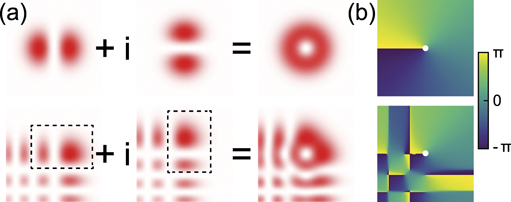
Figure 1. (a) The superposition of HG10 and HG01 modes to form an LG01 mode and the superposition of two Airy beams into a new-type vortex Airy beam with a vortex-containing lobe. (b) Plots of the phase distributions of the new-type fields. The white dot indicates the location of the main singular point.
Download figure:
Standard image High-resolution imageWe here express a new-type vortex Airy beam with ℓ = ±1 OAM as

where bk
and  , respectively, represent the kth real zeros of Ai(⋅) and
  and
and  [31]. The total power of the new-type vortex Airy beam in the beam cross section is derived from Parseval's theorem as

An a0 = 0 new-type vortex Airy beam, while being a non-real solution to the paraxial equation owing to its infinite power, is truly propagation-invariant. We consider this beam to be a perfect vortex Airy beam. As expected, when a0 > 0, the new-type vortex Airy beam has a finite energy distribution.
New-type vortex Airy beams with higher-order OAM can be obtained through the superposition of more than two Airy beams. For example, a new-type vortex Airy beam with ℓ = ±2 OAM is expressed as follows:

2.2. Propagation dynamics of the main singular point
We show that the new-type vortex Airy beam has a vortex lobe which remains stationary (i.e. the position of the singular point does not change with respect to the parabolic trajectory) as the distance from the focus  changes. This is in contrast to a conventional vortex Airy beam; the characteristic of which is shown in figure 2(a). The deformation of the intensity distribution of the conventional vortex Airy beam is attributed to the main singular point leaving the parabolic trajectory
  with respect to propagation distance (further discussion is described in appendix
  the main singular point does follow a parabolic trajectory; this can be seen through solution of equation (3) as follows:

Moreover, the perfect new-type vortex Airy beam maintains the same intensity distribution for any propagation distance; this is shown in figure 2(b).
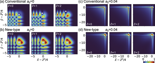
Figure 2. Propagation dynamics of new-type vortex Airy beams with ℓ = +1 OAM and conventional vortex Airy beams with ℓ = +1 OAM. White dots represent the positions of the ℓ = +1 main singular points. (a) Intensity distribution of the perfect conventional vortex Airy beam. (b) Intensity distribution of the perfect new-type vortex Airy beam. (c) Intensity distribution of the a0 = 0.04 conventional vortex Airy beam. (d) Intensity distribution of the a0 = 0.04 new-type vortex Airy beam. The formula of the conventional vortex Airy beam is expressed in equation (A.4).
Download figure:
Standard image High-resolution imageWhile the intensity distribution of the perfect new-type vortex Airy beam can be theoretically modeled, it is a non-real solution to the paraxial equation. Real solutions with a0 > 0 have also been investigated in this work. In such cases, we observe that there is some deviation of the main singular point from the parabolic trajectory, as the beam propagates away from focus. The amount of deviation  (as described in appendix
  for different values of a0 are shown in figure 3.
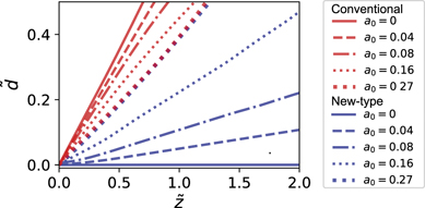
Figure 3. The amount of deviation  of the main singular point from the parabolic trajectory.
Download figure:
Standard image High-resolution imageWhen a0 = 0.27, the amplitude envelope of the new-type vortex Airy beam decays to 1/e times in the main vortex lobe since  . Usually, the exponential truncation factor is experimentally made small (a0 ≪ 1). The smaller a0 is, the smaller the amount of deviation
  is at the same propagation distance for the new-type vortex Airy beams, in comparison with conventional vortex Airy beams. If we consider the case where a0 = 0.04, the 1/e decay of the new-type vortex Airy beam is in its 26th side lobe since
  . Here, the new-type vortex Airy beam preserves the ring shape of the main vortex lobe (as shown in figure 2(d)) as it propagates, whereas the main vortex lobe of the conventional vortex Airy beam separates as it propagates (as shown in figure 2(c)). We find that for
  values ≲0.1, the ring shape of the main vortex lobe is well-preserved upon propagation and the singular point follows the parabolic trajectory. This is detailed in appendix
2.3. Orbital angular momentum spectrum
As vortex Airy beams are not symmetric around the main singular point, they carry not only ℓ = +1 OAM, but also the other OAM across their profile. Here we examine the OAM spectrum of these vortex Airy beams. The OAM spectrum of the electric field envelope φ at  is defined by

where m represents the topological charge (or OAM in a reduced Planck constant  ,
,  and
and  are the normalized radius and the azimuthal angle of the polar coordinates in the transverse plane respectively [32]. Figure 4 shows the absolute amplitude distributions of the OAM spectra of the perfect conventional vortex Airy beam with ℓ = +1 OAM and the perfect new-type Airy vortex beam with ℓ = +1 OAM. In the inner part of the main vortex lobe
  , both of the beams mainly contain m = 1 optical vortex modes. Figure 5 shows a plot of the OAM spectrum of the inner part of the main vortex lobe of both conventional and new-type vortex Airy beams, where the intensity (Im
) is derived as
, both of the beams mainly contain m = 1 optical vortex modes. Figure 5 shows a plot of the OAM spectrum of the inner part of the main vortex lobe of both conventional and new-type vortex Airy beams, where the intensity (Im
) is derived as  . The mode purity of the perfect new-type vortex Airy beam is 91%, while that of the perfect conventional Airy vortex beam is 81%. Thus, the new-type vortex Airy beam is superior in terms of OAM mode purity as well as beam propagation characteristics.
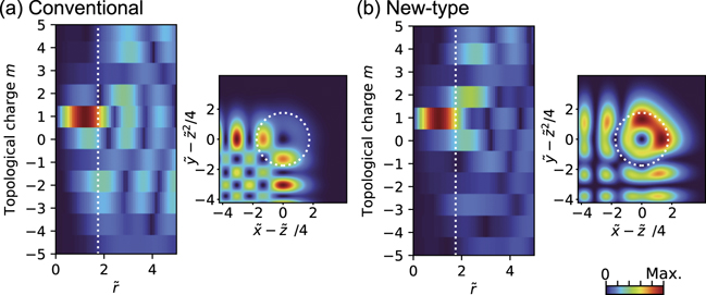
Figure 4. The absolute amplitude distributions of OAM spectra of (a) the perfect conventional Airy beam with ℓ = +1 OAM and (b) the perfect new-type vortex Airy vortex beam with ℓ = +1 OAM at  . To clearly resolve the OAM modes, including unwanted modes, the spectral distributions of their absolute amplitude are plotted. The intensity distributions in the real space are also displayed next to the OAM spectra. The white dotted lines indicate
  .
.
Download figure:
Standard image High-resolution image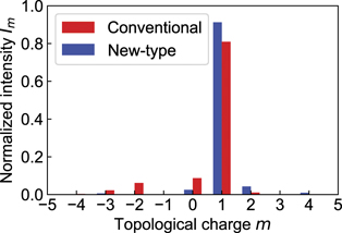
Figure 5. OAM spectra of the inner part  of the main vortex lobe of the perfect new-type vortex Airy beam with ℓ = +1 OAM and the perfect conventional Airy vortex beam with ℓ = +1 OAM at
  .
.
Download figure:
Standard image High-resolution image3. Experimental results and discussions
3.1. Experimental setup
We experimentally investigated the propagation dynamics of new-type vortex Airy beams, generated from an in-house-built Ti:sapphire regenerative amplifier pulsed laser system. The output from this laser was horizontally polarized and had a Gaussian spatial profile with a beam radius of 3 mm. Spectral purity was maintained by passing the beam through a bandpass filter (central wavelength, 800 nm; bandwidth, 5 nm). The laser beam was then incident on a spatial light modulator (SLM) which acted as a phase mask. The details of the phase mask displayed on the SLM can be found in appendix  mm). Using a CMOS imaging sensor in conjunction with a mechanical stage, we recorded the profiles of the generated vortex Airy beams at different propagation distances, in the vicinity of the focus. For comparison purposes, we generated a conventional vortex Airy beam by implementing a phase mask with a sum of a cubic and a spiral phase distribution on the SLM [33].
3.2. Results and discussion
Figure 6 shows the experimental propagation dynamics of a finite-energy new-type vortex Airy beam with ℓ = +1 OAM and a finite-energy conventional vortex Airy beam with ℓ = +1 OAM. The factors of the transverse plane, the propagation axis and the exponential truncation were evaluated to be x0 = y0 = 0.06 mm, z0 = 30 mm and a0 = 0.04, respectively. The propagation dynamics of the conventional vortex Airy beam (figure 6(a)) and the new-type vortex Airy beam (figure 6(b)) clearly agree well with the numerical simulations shown in figures 2(c) and (d), respectively. The main vortex lobe of the finite-energy conventional vortex Airy beam deformed at  and finally divided into two spots at
  , which as mentioned is attributed to the main singular point deviating from the parabolic trajectory. In contrast, the main vortex lobe of the new-type vortex Airy beam maintained its ring shape even at
  . This is consistent the main singular point of this new-type vortex Airy beam following the parabolic trajectory (as expected, given
  was small).
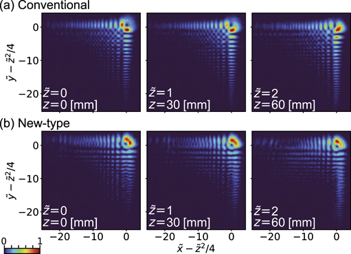
Figure 6. Experimentally acquired intensity distributions of (a) the a0 = 0.04 conventional vortex Airy beam with ℓ = +1 OAM and (b) a0 = 0.04 new-type vortex Airy beam with ℓ = +1 OAM at  .
.
Download figure:
Standard image High-resolution imageIn order to show that a new-type vortex Airy beam has an ℓ = 1 singular point in the main vortex lobe, we implemented an interference measurement at  with a reference beam (figure 7). This was done using the random mask encoding method [21] wherein both object and reference beams were simultaneously generated from the same phase mask. The interference image had a two-pronged fork pattern in the main vortex lobe (figure 7(a)) and this was consistent with that predicted via numerical simulation (figure 7(b)). Thus, the dominant topological charge of the main vortex lobe was +1 [34–36], which was consistent with the OAM spectrum shown in figure 5. These results indicate that these new-type vortex Airy beams comprise a new family of vortex Airy beams. We note that there are other families of vortex Airy beams such as circular [37], elliptical [38, 39], and symmetric [40–42] vortex Airy beams. Since having an abruptly autofocusing property [43, 44], these beams are totally different from the new-type vortex Airy beams.
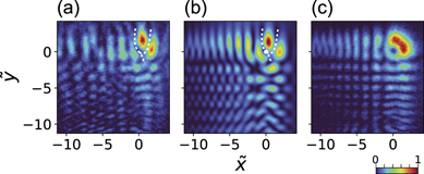
Figure 7. (a) Observed image and (b) numerical calculation image of interference pattern at  . The white dot in (b) represents the main singular point. (c) Observed image without a reference beam at
  .
.
Download figure:
Standard image High-resolution imageWe discuss whether the new-type vortex Airy beams can be generated by the astigmatic transformation. Astigmatic mode converters can output an LG mode from a certain HG mode [45, 46]. From the analogy shown in figure 1, one may think that the new-type vortex Airy beam can be generated by the astigmatic transformation of an Airy beam rotated by a 45 degree angle. The astigmatic transformation is based on the synthesize of eigenmodes with phase shifts among them; in addition, the eigenmodes share a common beam axis. Since being a superposition of Airy beams whose beam axes are parallel shifted from each other, a new-type vortex Airy beam does not match the beam generated through the astigmatic transformation of an Airy beam rotated by a 45 degree angle. In contrast to that, the specular Airy beams, having mirror symmetry in its intensity profile, can be transformed into the vortex mode through an astigmatic mode converter [47]. The astigmatic transformation of an Airy beam and its family is an interesting topic of future work.
We comment on future applications of the new-type vortex Airy beams. It has been pointed out that the Airy beam carries relatively more optical power in the main lobe compared with a Bessel beam [16]. The power fractions in the main vortex lobe of the new-type vortex Airy beam are calculated to be 28% (for  and 71% (for
  . Thus, we expected the new-type vortex Airy beam can carry high power in the main lobe, which benefits microscopy in terms of improving the signal noise ratio and applications need high power laser beam. Moreover, the dark spot of the singular point is well-preserved in the region of
  , although the shape of the main vortex lobe is not perfectly symmetric especially on propagation. The new-type vortex Airy beams are expected to possess the self-healing properties since they are indeed composed of Airy beams, while it is needed to examine of their self-healing properties in future work. Thus, they can be useful for the STED beam in STED-SPIM. Light-sheet imaging [11–14], material processing [48–50] and nonlinear optics [51] may be another fruitful direction.
4. Conclusion
In conclusion, we have presented theoretical and experimental investigations into the generation of a new-type vortex Airy beam. These beams exhibit very stable propagation dynamics compared to conventional vortex Airy beams, wherein the position of the singular point within the beam intensity profile does not vary significantly on propagation from focus. This is in contrast to conventional vortex Airy beams which exhibit significant movement of the singular point with beam propagation. We anticipate that the propagation-insensitivity of the singular point in these new-type vortex Airy beams may herald new innovations in applications such as STED microscopy, light-sheet imaging, material processing and nonlinear optics.
Acknowledgments
This work was partially supported by Core Research for Evolutional Science and Technology program (No. JPMJCR1903) of the Japan Science and Technology Agency (JST) and Kakenhi Grants-in-Aid (Nos. JP16H06506, JP17K05069, JP20H02645) from the Japan Society for the Promotion of Science (JSPS).
Data availability statement
All data that support the findings of this study are included within the article (and any supplementary files).
Appendix A.: Conventional vortex Airy beam
In this section, we derive a formula which describes a conventional vortex Airy beam that introduced in reference [21]. The electric field envelope of the Airy beam

satisfies the normalized paraxial equation of monochromatic electromagnetic waves with wavenumber k

where  is a normalized axis in the beam cross section, x0(=y0) is a scale factor of the transverse plane,
  is a normalized propagation axis,
  defines the lateral shift of the Airy beam, and a is a truncation factor.
When an OAM operator  [52] commutes with the operators
  ,
,  , and
, and  on both sides of equation (A.2), we get

thus  is also a solution of equation (A.2). The explicit form of
  is given by

where  is a vortex array imposed on an Airy beam (figure A1). The emergence of a vortex array was reported in the first study of vortex Airy beams [21]. In general, the OAM operator L± adds an OAM ℓ = ±1. For example, when the OAM operator acts on a Laguerre–Gaussian mode with the radial index p and azimuthal index ℓ (LGpℓ
mode), the mode will be converted into the LGp(ℓ±1) mode [52].
is a vortex array imposed on an Airy beam (figure A1). The emergence of a vortex array was reported in the first study of vortex Airy beams [21]. In general, the OAM operator L± adds an OAM ℓ = ±1. For example, when the OAM operator acts on a Laguerre–Gaussian mode with the radial index p and azimuthal index ℓ (LGpℓ
mode), the mode will be converted into the LGp(ℓ±1) mode [52].  (equation (A.4)), however, has the terms of an Airy beam as well as that of a vortex array Airy beam, the characteristic of which causes a degradation of the beam profile with distance from its focus
  . Note that equation (A.5) differs from the results of Huygens–Fresnel integral [53] because the initial optical field condition (the electric field envelope at
  is not the same.
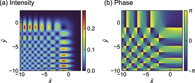
Figure A1. (a) Intensity and (b) phase profiles of a vortex array Airy beam  .
.
Download figure:
Standard image High-resolution imageHere we show a beam described by equation (A.4) which is generated by the spatial Fourier transformation of an LG01 mode modulated by a cubic phase. The inverse spatial Fourier transform of the Airy beam at  is defined as

where  is a normalized wavenumber in the transverse plane [21]. When a ≪ 1, we get

The spatial Fourier transform of equation (A.7) is

which physically means that a Gaussian beam whose beam radius is a−1/2 with a cubic phase  , propagating through a Fourier lens, generates a finite energy Airy beam at its focus. From equation (A.8), a beam described by
  is obtained by Fourier lens transformation of LG01 mode beam with a cubic phase,
A conventional vortex Airy beam is usually generated by applying the sum of a cubic phase and a spiral phase to a Gaussian beam [21, 22, 33]. We assume that the radius of the Gaussian beam is  . When
  , ∼96% of the phase modulated Gaussian beam is the phase modulated LG01 mode beam in terms of energy ratio. Most parts of the conventional vortex Airy beam is described by equation (A.4). Thereby, obtaining the simple expression of conventional vortex Airy beam, we regard
  as
as  .
.
Appendix B.: Propagation dynamics of the main vortex lobe of the new-type vortex Airy beam
The position of the singular point  of the main vortex lobe of a finite energy new-type beam shifts from the parabolic trajectory
  . The shift
  can be numerically fitted by hyperbolic tangent functions
ℓ = ±1 and ℓ = ∓1 singular points appear at  . The former one is the singular point of the main vortex lobe. This singular point collides with another ℓ = ∓1 singular point, following which these points vanish at
  (figure B1).
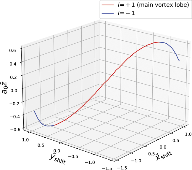
Figure B1. Trajectories of singular points of the new-type vortex Airy beam with ℓ = 1 OAM.
Download figure:
Standard image High-resolution imageThe main vortex lobe of a finite energy new-type vortex Airy beam deforms with propagation distance. Figure B2 depicts propagation dynamics of various new-type vortex Airy beams at  and 0.5. The shape of the vortex lobe resembles a closed ring at
  , and it becomes progressively more open as the value of
  increases, as seen for
  and
and  . This characteristics is due to the deviation of the main singular point from the parabolic trajectory
  , which is significant with respect to the size of the vortex main lobe.
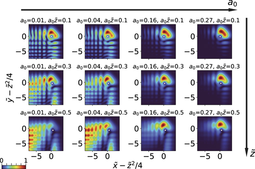
Figure B2. Propagation dynamics of ℓ = 1, a0 = 0.01, 0.04, 0.16 and 0.27 new-type vortex Airy beams at  and 0.5. White dots represent the position of the main singular point.
Download figure:
Standard image High-resolution imageAppendix C.: Phase mask for new-type vortex Airy beam
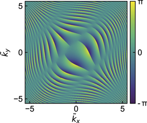
Here we detail the characteristics of the phase mask used to tailor a new-type vortex Airy beam. The Fourier transform of a new-type vortex Airy beam is described by the following expression
where bk
and  represent the kth real zeros of Ai(⋅) and
  and
and  respectively [31]. We assume the input beam is a Gaussian beam with beam radius
  in the
  plane. Since we need both phase modulation and amplitude modulation through a phase mask, we calculated the phase mask pattern by using the Davis's method [54–56]. Figure C1 shows the phase distribution that we displayed on the SLM. When a0 = 0.04, the radius of the Gaussian beam is
  in the
  plane.
Figure C1. Phase distribution of the phase mask without the carrier phase modulation for a new-type vortex Airy beam with ℓ = 1 OAM.
Download figure:
Standard image High-resolution image