


Abstract
The heating neutral beam injectors (HNBs) of ITER are designed to deliver 16.7 MW of 1 MeV D0 or 0.87 MeV H0 to the ITER plasma for up to 3600 s. They will be the most powerful neutral beam (NB) injectors ever, delivering higher energy NBs to the plasma in a tokamak for longer than any previous systems have done. The design of the HNBs is based on the acceleration and neutralisation of negative ions as the efficiency of conversion of accelerated positive ions is so low at the required energy that a realistic design is not possible, whereas the neutralisation of H− and D− remains acceptable (≈56%).
The design of a long pulse negative ion based injector is inherently more complicated than that of short pulse positive ion based injectors because:
• negative ions are harder to create so that they can be extracted and accelerated from the ion source;
• electrons can be co-extracted from the ion source along with the negative ions, and their acceleration must be minimised to maintain an acceptable overall accelerator efficiency;
• negative ions are easily lost by collisions with the background gas in the accelerator;
• electrons created in the extractor and accelerator can impinge on the extraction and acceleration grids, leading to high power loads on the grids;
• positive ions are created in the accelerator by ionisation of the background gas by the accelerated negative ions and the positive ions are back-accelerated into the ion source creating a massive power load to the ion source;
• electrons that are co-accelerated with the negative ions can exit the accelerator and deposit power on various downstream beamline components.
The design of the ITER HNBs is further complicated because ITER is a nuclear installation which will generate very large fluxes of neutrons and gamma rays. Consequently all the injector components have to survive in that harsh environment. Additionally the beamline components and the NB cell, where the beams are housed, will be activated and all maintenance will have to be performed remotely.
This paper describes the design of the HNB injectors, but not the associated power supplies, cooling system, cryogenic system etc, or the high voltage bushing which separates the vacuum of the beamline from the high pressure SF6 of the high voltage (1 MV) transmission line, through which the power, gas and cooling water are supplied to the beam source. Also the magnetic field reduction system is not described.
Export citation and abstract BibTeX RIS

Original content from this work may be used under the terms of the Creative Commons Attribution 3.0 licence. Any further distribution of this work must maintain attribution to the author(s) and the title of the work, journal citation and DOI.
1. Background, basic parameters and basic design principles
ITER will initially be equipped with 2 heating neutral beam injectors (HNBs) that are designed to deliver 33.3 MW of either 1 MeV D0 or 0.87 MeV H0 to the ITER plasma for up to 3600 s. A third HNB may be installed at a later date. The beam energy needs to be above ≈300 keV in order to deposit the power inside the H-mode transport barrier when ITER is in the so-called 'H-mode'. D0 or H0 beams can only be created at such energies with an acceptable efficiency by the neutralisation of accelerated D− or H−. The choice of 1 MeV as the D0 beam energy is a compromise between the need to deposit power across the minor radius of the ITER plasma and to drive current in the plasma and the technological difficulties of developing the high voltage power supply and producing the required accelerated D− current density. When an accelerator optimised for D− and the required accelerated current of 40 A at 1 MeV is operated with H−, optimised beam optics are achieved at 870 kV with an accelerated current of 46 A. The neutralisation, beam transmission and other losses in the beamline will be similar for H− and D−, and the injected H0 or D0 power should be 33 MW from the 2 HNBs. H0 beams will be used in the early, non-nuclear, phases of ITER operation. Operation in H− is expected to be essentially the same as with D−, so, for simplicity, only D− operation is discussed in the following text. Figure 1 shows a general view of an HNB.

Figure 1. Computer generated cut-away view of an ITER HNB beamline. The blue rectangles above and below the NB vessel are magnetic field compensation coils.
Download figure:
Standard image High-resolution imageThe actual characteristics of the beam from the ITER HNB beam source are not yet known, therefore for design purposes they have to be assumed, with the assumptions based on experimental data from existing high energy negative ion beam systems. The general requirements for the beamline component design are: maximum beam duration 1 h, beamlet divergence of 3, 5 or 7 mrad with 15% of the power in each beamlet carried by a 'halo' fraction with a divergence of 30 mrad. A beamlet divergence of 3 mrad and 40 A of accelerated D− would lead to ≫16.5 MW being injected into ITER per HNB and to excessive power densities on some beamline components and a fatigue life for some components that is shorter than the lifetime of ITER. Therefore if the beamlet divergence is found to be ≈3 mrad, the accelerated D− power will be reduced such that 'only' 16.5 MW is delivered to the ITER plasma per HNB, which avoids both the excessive power densities and the short fatigue lives.
In addition to the above, for design purposes it is assumed that the beam may be horizontally misaligned by ≤±2 mrad, and vertically misaligned by ≤±4 mrad and that the beam can be tilted by ≤±10 mrad from the nominal downward inclination of 49.2 mrad.
The ITER ion source is an extrapolation of the radio frequency (RF) driven negative ion source developed at IPP, Garching, Germany [1] attached to a multi-aperture extractor and a 5 stage, multi-aperture, electrostatic accelerator. The ion source is held at −1 MV and the D− is accelerated up to ground potential. As D− is easily lost by collisions with D2 in the extractor and accelerator, to minimise the losses the pressure at the accelerator exit is kept as low as possible by separating the accelerator from the neutraliser to allow the gas exiting both the accelerator and the neutraliser to be pumped away from the gap between the two components.
The beam emerging from the neutraliser will consist of ≈56% D0 and 22% each of D− and D+, and the charged particles are removed from the beam by the residual ion dump (RID). The neutral beam (NB) leaving the RID can be intercepted on a V-shaped calorimeter, or the two panels making up the V can be rotated so that they sit either side of the beam so that the NB can continue towards the plasma in ITER. The calorimeter intercepts the beam during the commissioning of the system. With the calorimeter open, the beam enters the duct to ITER and finally the ITER vessel. A cooled scraper at the exit of the HNB vacuum vessel prevents direct beam interception on the vessel7 , and cooled panels in the duct catch divergent parts of the beam and any charged particles created by collisions between the beam and residual gas in the duct. Immediately after the beam exits the injector vessel it passes through a fast shutter (FS) and an absolute valve (AV). The former is normally closed when there is no injection into ITER and it prevents the ingress of unwanted gas into the injector. The AV can be used to isolate the injector from the ITER should there be a vacuum fault in either of them.
The components of the HNBs are all designed to be capable of operating throughout the lifetime of ITER, taking into account material ageing, creep and fatigue. The total expected beam-on time of an HNB is ≤1.98 × 10⁷ s, with ≤5.0 × 10⁴ beam-on/off pulses and ≤4.5 × 10⁵ electrical breakdowns in the extractor and accelerator [2].
To avoid the adverse effects of any additional magnetic fields on the performance of the beam source and any significant deflection of the charge particles in the upstream of the RID, it is essential to minimise the stray field from ITER upstream of the RID. The magnetic field reduction system is composed of a total thickness of 150 mm of soft iron surrounding the HNB vacuum vessel and a set of active field compensation coils located above and below the injector. The design of that system is not discussed below.
The main beamline components, i.e. the neutraliser, the RID and the calorimeter are placed upon adjustable beds on the bottom of the HNB vacuum vessel. These allows the components to be displaced by ±40 mm horizontally and ±20 mm axially, which allows them to be accurately aligned inside the vacuum vessel with respect to the beam axis.
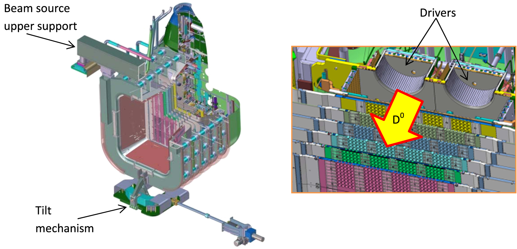
2. The beam source
The beam source, which consists of the ion source, the extractor, the accelerator, the grid support structure, overall adjustment of the beam aiming and position, and the beam source tilting mechanism, is designed for the production of beam for up to 3600 s. Therefore all internal parts facing charged particles, either plasma, ions or electrons, are subjected to heat loads which require active cooling. The highest power loads are on the acceleration grids and the rear back-plates of the ion source. (The latter is due to back-streaming positive ions.) The power to each of the acceleration grids is >1.2 MW, and the power to the ion source back-plates is ≈1 MW. The local maximum power density on the acceleration grids and the extraction grid (EG) is of the order of 10 MW m−2, (see section 4). The maximum power density on the ion source back-plates due to the back-streaming positive ions is calculated to be ≈60 MW m−2 [3].
In order to cool the high power density regions, small cooling ducts are embedded in the thickness of the copper (Cu) grids with the thickness of the Cu layer on the power receiving side reduced to about 1.5 mm in order to maximise the efficiency of power removal with an acceptable surface temperature. Such a configuration is obtained by machining the channels into a Cu baseplate followed by electro-deposition of copper to close the top of the cooling channel and to form the final required thickness of Cu above the cooling channels.
2.1. Ion source
The RF ion source is composed of a rectangular 'expansion chamber', three caesium (Cs) ovens, and 8 cylindrical 'drivers' attached to the rear wall of the expansion chamber. A 'bias plate' and the first grid of the extractor (the plasm grid) form the front wall of the source.
Each driver consists of a ceramic cylinder mounted with its axis horizontal, a Faraday screen inside the cylinder, a metal back-plate that closes both the rear end of the Faraday cage and the ceramic cylinder, a coil wound around the ceramic cylinder and a directly heated tungsten 'starter' filament. The fields generated inside the Faraday cage by the RF applied to the coils together with electrons from the starter filament ionise the gas and create plasma inside the Faraday cage. Once initiated, the starter filaments can be turned off as the RF power alone suffices to sustain the plasma. The field from permanent magnets embedded in the back-plate of the driver minimises plasma loss to the back-plate. Plasma flows from open end of the driver into the expansion chamber. Caesium (Cs) from the ovens is injected into the expansion chamber and deposited on the walls of the expansion chamber, the plasma grid (PG) and the bias plate. It is necessary to have Cs on the PG as that reduces its work function and allows negative ions to be more easily created when atoms and positive ions from the plasma in the expansion chamber impinge on the PG. An essential feature of the ion source is the current of <4 kA that will flow from the top to the bottom of the PG. That current creates a horizontal magnetic field in front of the PG which inhibits the flow of electrons to, and through, the PG, thus reducing the extracted electron current (see section 3).
All the metal surfaces facing the plasma inside the ion source are made of copper (Cu) that is coated with molybdenum. The sputtering yield for D+ and  incident on Mo is very much lower than that for Cu, so the Mo coating minimises any sputtering which could otherwise contaminate the Cs layer on the PG. In general the coating is achieved by plasma vapour deposition and the layer thickness is ≈5 × 10⁻⁶ m. The exceptions are the back-plates of the expansion chamber and the drivers. On those an explosion bonding technique will be used to create a coating 1 mm thick, which is calculated to be the thickness needed to ensure that the coating is not compromised by sputtering due to back-streaming positive ions within the foreseen lifetime of ITER [4].
2.2. Extractor and accelerator
The extractor and accelerator consist of sets of multi-aperture grids at various potentials between −1 MV and 0 V. each grid is supported from the upstream and downstream grid by sets of cylindrical ceramic 'post insulators' situated around the periphery of the grid support structure (see figure 2). Each end of each post insulator is enclosed within an electrostatic shield so that electric field at the triple point (the junction between the ceramic, the metal and vacuum) is minimised as it is known that high fields at the triple point can induce high voltage breakdowns. The grounded grid (GG) is supported from a transverse metal beam above the beam source in the beam source vessel (BSV) and below by the beam source tilting mechanism. The lower support can be moved to tilt the whole beam source about the upper support beam in order to tilt the accelerated beam upwards or downwards by the required ±9 mrad.

Figure 2. Computer generated cut-away views of the HNB beam source.
Download figure:
Standard image High-resolution imageThe extractor consists of two grids, the PG and the EG, followed by 5 acceleration grids. When producing a 1 MeV beam, the PG is at −1 MV, the EG at ≈−0.99 MV, and the following acceleration grids at −0.8, −0.6, −0.4, −0.2 and 0 MV. The last grid is usually referred to as the 'GG'. A negative ion exiting the ion source through one of the apertures in the PG is accelerated in the resultant electric field towards the EG and it will then pass through the corresponding aperture in the EG. The ion is then further accelerated towards the next acceleration grid and so on until it passes through the final, grid, which is at ground potential. Magnetic fields in the extractor and accelerator deflect electrons so that few manage to pass through the downstream grids, thus minimising the useless acceleration of electrons (see section 3).
All the grids are ≈1.6 m high and ≈0.8 m wide. They consist of four segments stacked vertically, each ≈0.4 m × ≈0.8 m, for alignment and manufacturing reasons. Each grid has 1280 apertures, 320 per segment. The apertures are arranged in 16 rectangular arrays, each with 5 vertical columns of 16 apertures. In the case of the EG and the acceleration grids, except the 0 kV grid, it is required to embed permanent magnets in the grids (see section 3). The channels to accommodate the magnets are formed in a similar way to the cooling channels, but on the downstream side of the baseplate.
The mechanical design fulfils several different requirements for the most heated components, particularly:
- maximum temperature (200 °C), to keep acceptable mechanical properties in the copper;
- an acceptable stress distribution in the copper;
- a fatigue life (5 × 10⁴ beam on-off cycles) that satisfies the ITER design standards;
- acceptable thermal deformation of grids.
To ensure the required beam optics (see section 4), the relative positions of the apertures in the PG, EG and the GG must be fixed within ≤±0.2 mm, which is very difficult with the large structures concerned. The positions of the apertures in the other grids must be aligned with the expected beamlet axes, but the alignment is less critical as the apertures in those grids form very weak, or no, electrostatic lenses. To obtain the required alignment accuracy requires very accurate machining of the dowels, the dowel hole and slot, and the apertures, and precise temperature control of the workpiece during machining. The assembly and positioning procedure must ensure that each segment of each grid is positioned with respect to a reference coordinate with sufficient accuracy. To achieve that each of the 4 grid segments is fixed into a supporting plate that is attached to the grid support, and each grid segment and the supporting plate will be precisely machined with two calibrated dowels that fix the position of each segment when it is assembled onto the support plate. One dowel passes through a precision machined hole in the segment on the cooling water inlet side, whilst the other passes through a precision machined slot on the water outlet side. The dowel hole and the axis of the dowel slot are located at the segment vertical centreline, which allows free thermal expansion across the segment under nominal conditions. Adjusting elements between the external flanges and the support plates will allow horizontal and vertical adjustment of each grid even at the end of the assembly, in order to match the demanding alignment requirements.
As is mentioned in sections 3 and 4, stripping losses inside the HNB accelerators are significant, and they must be minimised. That means that the grid supports have to be as 'open' as possible to gas flow, so that the accelerator is pumped efficiently. Therefore the gaps between adjacent grid support structures have been maximised and the surfaces made as smooth as possible.
Once the assembled beam source is mounted in the BSV and operational, its position must be adjustable in order to ensure that the extracted beam passes optimally through the neutraliser and the RID (see sections 5 and 6). Also, calculations show that beams can excite toroidal Alfvén eigenmodes [5], resulting in a degradation of the confinement of a plasma in a tokamak. Tilting the beam source, thus tilting the beam, means that the positions of the beams in the ITER plasma move vertically, reducing the overlap between beams from different HNBs, which may allow those modes to be avoided.
Figure 2 gives a cut-away view of the beam source that allows some of the features discussed above to be appreciated. The physics aspects of this accelerator are described in detail in [6], whereas the more technical aspects are described in [7].
3. Magnetic configuration of the beam source
Magnetic fields in the beam source play an essential role in the performance of the ion source, in determining the extracted electron current and in the control of electrons created in the accelerator:
3.1. 'Long range' magnetic field in the ion source, extractor and accelerator
In the plasma source, a transverse 'filter field' upstream of the PG is necessary to reduce the losses of D− due to 'fast' electron collisions and the number of co-extracted electrons. However the field can also affect the plasma homogeneity in front of the PG and the extracted D− current density. Based on experience with the sources at IPP Garching, a magnetic filter field strength between 2 and 4 mT is required upstream of the PG. As mentioned above, the field will be produced by a current flowing in the PG, but if the strength of the field so induced is >2 mT in the drivers it can affect the plasma production in the drivers.
On the downstream side of the PG (in the extractor and accelerator) a transverse 'long-range field' is needed to deflect electrons generated in the plasma onto the next downstream grid to avoid useless acceleration of such electrons, to reduce the power to the grid, and to minimise the heat load on the downstream beamline components, especially the cryopumps, due to energetic electrons exiting the accelerator.
The current design of the magnetic field both inside the ion source and in the extractor and accelerator has been obtained by optimising the geometry of the current-feeding bus-bars. The nominal PG current is ≈3 kA for hydrogen operation and ≈4 kA for deuterium operation.
3.2. Electron suppression in the EG, configuration and field compensation
'Electron suppression magnets' (ESMs), which are embedded in the EG are arranged in horizontal rows between the rows of apertures. They are polarised parallel to the beam direction, and the polarity alternates between adjacent rows. This layout produces a vertical component of the induction field (By) characterised by two symmetric peaks of opposing polarity along the axis of each beamlet. The field upstream of the EG is calculated to be sufficient to deflect the co-extracted electrons onto the EG. Unfortunately, the magnetic field of the ESMs would also induce an undesired 'zig-zag' deflection of the extracted and accelerated ions, the direction of which alternates from aperture row to aperture row. To a first approximation, the angular deflection is proportional to the net value of the integral of By along the ion trajectory from the starting point, i.e. the meniscus at the PG aperture, to the point at which the field becomes negligible. That deflection, which would be ≈±3 mrad, must be corrected in order to avoid beam loses downstream of the accelerator. That is achieved by embedding a second set of magnets in the EG (referred to as ADCM below) which are placed vertically beside each aperture of the EG and magnetised along the vertical direction. Their effect is to increase the magnetic field produced by the ESMs on the upstream side of the EG, and to decrease it on the downstream side, which is calculated to eliminate the net deflection of the ions [8].
3.3. ESMs in the first 4 acceleration grids
Simulations have shown that, in addition to the long-range field in the accelerator, a magnetic field is needed inside the accelerator to deflect electrons away from the ion trajectory so that the majority of them impinge on the first acceleration grid downstream of their creation point, which minimises the number of electrons that can pass through the apertures in the grids and the consequent further acceleration of those electrons. The required magnetic field is created partially by the long range field from the current through the PG and partially by magnets above and below each row of apertures in all the acceleration grids except the GG [6]. Those magnets are polarised parallel and antiparallel to the beam direction. The net result is a reduction in the heat load to the grids and a more uniform distribution of the power amongst the grids than when the magnets are absent.
4. Extractor and accelerator optics
As shown in figure 3, the beam is composed of 1280 'beamlets' formed by extracting the D− from 1280 apertures in the PG. Every grid of the extractor and accelerator is subdivided into 4 vertically stacked segments, each of which is composed of 4 aperture groups. The result is a matrix of 16 aperture groups, arranged in 4 columns of 4 beam groups. Each beam group consists of 5 × 16 apertures (a total of 1280 apertures). The apertures are separated by 20 mm in the horizontal direction and 22 mm in the vertical direction.
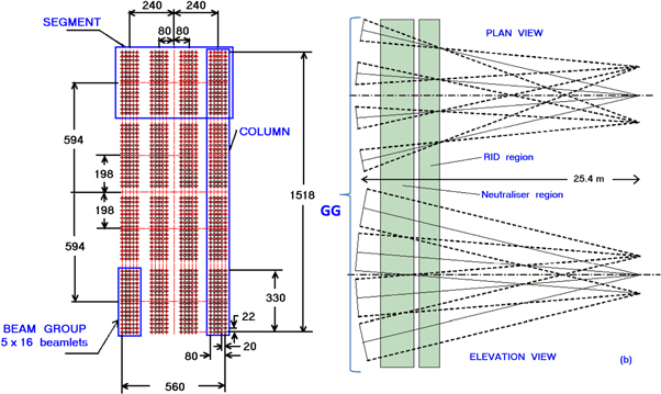
Figure 3. Aperture pattern on the GG (left-hand side) and beamlet aiming of the HNB accelerator for ITER (right-hand side).
Download figure:
Standard image High-resolution image4.1. Beamlet steering
For optimum beam transmission through the neutraliser, the RID, and the NB duct, all beamlets within a single group must be horizontally pointed to the centre of the exit of the relevant RID channel, at 7.2 m from the GG, and the beam from each segment must be tilted in such a way that they coincide in the duct, at 25.4 m from the GG [9], see figure 3.
The steering of the beams from the accelerator will be performed as follows [6]:
- (1)Orientation (tilting) of the segments of each grid in the vertical plane so that they all point at the vertical centre of the NB duct (see section 10) exit when the beam source is in its nominal, un-tilted, position.
- (2)Orienting the beam groups horizontally by machining of the grid segments so that they point at the vertical centreline of the exit of the appropriate channel in the RID.
- (3)The ≈±3 mrad zig-zag pattern caused by the ESMs in the EG is compensated for by the ADCM magnets, as discussed in section 3.2.
- (4)The outward deflection of beamlets due to the space–charge interaction between them is compensated for by attaching 3 mm thick 'kerbs' (see figure 4) around each aperture group on the downstream side of the EG. The edges of the kerbs are rounded to avoid electric field enhancement on sharp edges.
- (5)The steering of the beamlets within each group to the centre of the RID channel exit is performed by attaching kerbs of the same design as those on the EG to the downstream side of the first 4 acceleration grids.
The interaction between beam groups, the influence of the grid supports, the additional lensing effect caused by the non-flat grid surfaces and aperture centring require some fine adjustments to the kerb design.
4.2. Design of the plasma and EGs
The present design of the extractor, which is the combination of the PG and the EG, ensures a calculated clearance between the beam and the grid surfaces of 0.9 mm [6]. The extraction gap is 6 mm. The magnetic field from the ESMs deflects the co-extracted electrons onto the upstream surface of the EG, but due to electron backscattering and secondary electron production, there will be some electron 'leakage' through the EG apertures, which is calculated to be <2% of the extracted electrons.
4.3. Accelerator
For the 5-stage accelerator all metal-to-metal gaps are chosen to be ≥85 mm to ensure good voltage holding [10, 11]. 3 mm thick kerbs (see figure 4) will be attached to the downstream surface of the grids to steer the beamlets, so the gap between the apertures in neighbouring grids will be 88 mm. The grids are subject to high thermal load of ≤20 MW m−2 from the electrons and intercepted fast atoms and ions (fast atoms are created by stripping of the D− in the accelerator), and it was found necessary to enhance the cooling efficiency by splitting the cooling water channel as shown in figure 5. Nevertheless the grids will bend under the power load. The chosen thickness of the acceleration grids is 17 mm, which is calculated to keep the maximum out-of-plane bending to <0.8 mm [12].

Figure 4. Kerb design. Kerbs will be fitted to the downstream side of the EG and the first 4 acceleration grids.
Download figure:
Standard image High-resolution image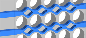
Figure 5. Two cooling channels in one of the acceleration grids.
Download figure:
Standard image High-resolution image4.4. Single beamlet optics
Using the code SLACCAD [13, 14] (a cylindrically symmetric Poisson solver), it is found that with an extracted current density of 284 A m−2 D− particles and zero ion temperature the single beamlet rms divergence will be 2 mrad, and that the clearance between beamlet and the aperture in the EG is 1.2 mm. With the gas density profile calculated using the view factor based code AVOCADO [15] the stripping losses are calculated to be 29%, so that the current density at the exit of the accelerator then becomes the 203 A m−2, which corresponds to a D− current of 40 A at the exit of the GG, i.e. with an energy of 1 MeV. Simulating an ion temperature of ≈0.5 eV in SLACCAD increases the optimum rms divergence to 3.4 mrad.
4.5. Stray particles
The EAMCC [3] code is used to calculate the powers, power densities and currents associated with secondary particles created in the accelerator. EAMCC tracks the stray particles in prescribed electric and magnetic fields and considers collisions with gas and accelerator grids, secondary electron production and electron back-scattering. Also particles passing through neighbouring apertures are correctly followed.
4.5.1. Back-streaming positive ions
Positive ions, mainly  and D+, are created in the accelerator by stripping reactions of D− on background gas and ionisation of background gas by D− [16]. Irrespective of the configuration of the magnetic field in the accelerator, it is found that ≈1 MW of back-streaming positive ion power is produced, most of which will load the back plates of the ion source.
4.5.2. Electrons and secondary electrons
Electrons are created in the accelerator by stripping reactions of D− on background gas and ionisation of background gas by D−, and by interaction of stray ions, neutrals and electrons with surfaces in the accelerator. If no magnetic fields other than the field from that of the ESMs in the EG are present in the accelerator, electrons created downstream of the EG are accelerated and transmitted out of the accelerator together with the negative ions; a calculated electron power of ≈5 MW would exit the accelerator. However, the magnetic fields present in the accelerator deflect the electrons onto the grid downstream of their creation point, preventing further acceleration and strongly decreasing the electron power at the exit of the accelerator, although the heat load on the intercepting grids is increased. Additionally the aperture diameters in the first 2 acceleration grids has been set to 14 mm, which maximises the electron interception whilst having a negligible interception of the accelerated D−. The diameters of the apertures in the downstream acceleration grids are 16 mm.
4.5.3. Beamlet 'halo'
It is found experimentally the accelerated D− beamlets have a 'halo', i.e. a high divergence fraction (perhaps ≈10%) of the D− in the beamlet have a divergence much higher than the main part of the beamlet, e.g. 30 mrad. (To be conservative a 15% halo is assumed for the beamline component design, as noted in section 1.) The halo is simulated in EAMCC by starting an additional 8% of the negative ions from an annulus around each aperture on the metal surfaces on the downstream side of the PG [17]. (As caesium from the ion source can migrate to the downstream surface of the PG, conversion of neutral Do to D− must occur.) Such particles are then accelerated and transmitted with high divergence through the accelerator, but many are intercepted on the downstream grids.
4.5.4. Power to the extractor and accelerator, back-streaming ion power and the power exiting the GG
Figure 6 shows the power loads on the various grid of the extractor and accelerator, the power from back-streaming positive ions into the ion source, and the power (except D−) transmitted through the GG into the beamline vessel as calculated by EAMCC.
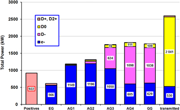
Figure 6. Power loads on the EG, the acceleration grids, power from back-streaming positive and the power exiting the accelerator (except D−) as calculated by EAMCC. (AG1, AG2, AG3 and AG4 are the acceleration grids at −.8, −.6, −.4 and −0.2°MV respectively.)
Download figure:
Standard image High-resolution image5. Neutraliser and electron dumps
Particles exiting the accelerator include electrons, D0 and D+ as well as D−. Fast D0 and D+ are created by stripping of the D− in the extractor and accelerator. The D0 that are not so divergent that they hit one of the grids will exit the accelerator, as will the D+ with sufficient energy to overcome the retarding field downstream of their birth point. The D0 and D+ that exit the accelerator will continue along the beamline and enter the neutraliser, with some D0 being converted to D+ by collisions with D2 in the gap between the accelerator and the neutraliser. The most dangerous particles exiting the accelerator are electrons as they will carry a substantial power. The back-scattering of electrons from metal surfaces is significant, and after >2 backscattering events some electrons could reach the thermal load sensitive panels of the cryopumps (see section 7). In the HNBs the electrons exiting the accelerator are deflected downwards by the long-range magnetic field from the beam source (see section 3) so that most of them are lost on a cooled electron dump below the entrance to the neutraliser and on the bottom of the neutraliser [18]. Other electron dumps are deployed at each side of the neutraliser entrance and on the vessel walls to catch most of the back-scattered electrons, see section 5.2.
The neutraliser and the electron dumps are water cooled, with the cooling channels being created in the various panel by deep drilling. Where the channel length is >1 m, the channels are drilled from both ends. The expected maximum drill deviation of 1 mm is fully compatible with the thickness of the panels. If enhanced cooling is required, and the channel is created by drilling from each end, a section of twisted tape is inserted from each end of the channel. That is the case for the leading edge elements of the neutraliser [19].
5.1. The neutraliser
Neutralisation is achieved via collisions with D2 inside the 'neutraliser', the relevant reactions being:


where ... represents all other possible products of the reaction. To reduce the neutraliser length whist keeping the gas flow into the neutraliser needed for the optimum neutralisation of the beam, the neutraliser is divided into 4 adjacent vertical channels and the gas is added midway along the neutraliser channel from 5 vertically disposed nozzles. Each channel is of rectangular cross-section, 3 m long, 1.7 m high, 105 mm wide at the beam entrance, and 90 mm wide at the exit of the channel, see figure 7. The channels walls are formed by 5 panels each made up of three 1 m long panels of oxygen free copper that is cooled by water flowing in deep drilled channels in the walls (a total flow of 55 kg s−1), and the maximum temperature of the Cu is kept below 150 °C. The out of plane deformation caused by the thermal loads is calculated to be <2 mm). The thermal stress due to the beam-on/off cycles causes fatigue, but, because the beam off time is short during a breakdown (≤0.1 s), the Cu temperature change is such that the thermal stress is low and it does not significantly impact the fatigue life. Overall the fatigue life consumption over the ITER lifetime is 7% of that available in the most loaded panel [19]. The inlet water temperature will be 38 °C and the pressure drop through the cooling circuit will be 0.4 MPa. The maximum outlet water temperature is calculated to be 70 °C.
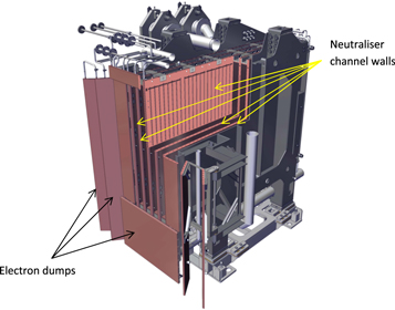
Figure 7. Section view of the neutraliser and the electron dumps.
Download figure:
Standard image High-resolution imageThe panel location and thickness are compatible with the beam aiming requirements; in particular the neutraliser entrance is located 1.9 m downstream of the GG, and the exit is 0.5 m upstream of the RID (see section 6). The gas exiting the neutraliser into the gaps between the neutraliser and the RID and the beam source is pumped away by the 2 cryopumps each side of the beamline (see section 7).
At the entrance to the neutraliser the channel walls are protected from the beam ions and neutrals and the fast electrons by 'leading edge elements' (LEs). The LEs will intercept power densities of ≤5 MW m−2 and a maximum power of 0.3 MW. The actively cooled LEs consist of CuCrZr bars with a rounded shape on the upstream side with an 18 mm diameter, 1.8 m long vertical cooling channel. Twisted tapes with a 70 mm pitch inside the cooling channels promote water turbulence. Finite element simulations show that with subcooled nucleate boiling conditions the critical heat flux condition is 17 MW m−2 assuming the Yagov correlation [2].
5.2. Electron dumps
Two louvre-like copper (Cu) panels are placed on each side of the neutraliser entrance and another electron dump panel is located below the neutraliser entrance, see figure 7. The louvre-like panels intercept some of the electrons exiting the accelerator and electrons back-scattered from the neutraliser and then from the downstream part of the beam source, its support structure or the vacuum vessel, reducing the electron power to the cryopumps from ≈100 to <1 kW [20]. These electron dump panels are positioned so as to allow the maximum gas flow to the cryopumps in order to reduce as much as possible the gas pressure between the beam source and the neutraliser. The maximum power density expected on the panels is calculated to be 0.17 MW m−2. The panels furthest out from the neutraliser are mounted on stainless steel (SS) support frames that can be rotated towards the neutraliser after the flow and return water lines have been cut. That is necessary to achieve the required minimum clearance (90 mm) between the panels and the cryopumps if the neutraliser is lifted out of the HNB for maintenance [19].
Cu 'electron dump' panels are also attached to the walls of the vacuum vessel upstream of the cryopumps, which prevent reflected electrons impinging on the vacuum vessel.
6. Residual ion dump
As mentioned in section 1, the beam emerging from the neutraliser will consist of ≈56% D0 and ≈22% each of D− and D+ (the 'residual' ions). The residual ions, must be removed from the beam in a controlled way inside the injector to avoid their deflection into the walls of the duct between the injector and ITER by the stray magnetic field from ITER, as that would lead to an unacceptable power load to the walls of the duct and an unacceptable level of re-ionisation of the NB (see section 11.3). Unlike in previous NB injectors, in the HNBs this will be done electrostatically rather than magnetically. The RID consists of 5 panels forming 4 vertical channels in line with the walls of the neutraliser channels. −20 kV is applied to the 2nd and 4th panels (counting from one side of the RID) and the ions entering the channels are deflected left or right depending on their charge, see figure 8. With this arrangement the RID fits within the limited available height and it spreads the charged particles over the 8 surfaces of the RID channels, reducing the peak power density on the panels. Should the beam optics be better than anticipated, an oscillating voltage can be added to the voltage on the 2nd and 4th panel to sweep the beam back and forward on all the panels. The effect of sweeping the additional voltage is to decrease the maximum average power density with a (very optimistic) 3 mrad beamlet divergence, with no halo fraction, from >8 (≈7) MW m−2 to ≈6 (5) MW m−2. (The numbers in parentheses refer to the case when the beamlet divergence is 3 mrad and the beam power is reduced to keep the injected power to 16.5 MW per HNB.)
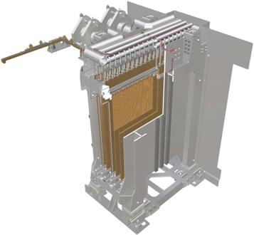
Figure 8. Cut-away view of the RID.
Download figure:
Standard image High-resolution imageThe RID panels are 1.8 m long, 1.7 m high. The entrance to the RID is 0.5 m downstream of the neutraliser exit, 5.4 m from the GG centre. The power density profile on the panels used for thermo-mechanical calculations corresponds to a 5% power excess to cater for possible changes in the neutralisation target. Each RID panel is made of 18 CuCrZr elements, with 4 cooling channels inside each element. Twisted tapes (70 mm twist pitch) inside the cooling channels act as a turbulence promoter and subcooled nucleate boiling can occur. The flow rate division amongst the elements of the panels is to be realised by varying the thicknesses of the twisted tapes in the cooling channels, with larger flow rates through the more heated elements [21]. The panel thickness is set at 22 mm and the diameter of the cooling channels in the elements is 14 mm With that drill diameter a channel deviation of ±1 mm is obtained for a drilling depth of 1 m, so resulting in metal thickness between the water channel and the vacuum is 4 ± 1 mm, which is consistent with design requirements [2]. The panel elements will be deep drilled from each end, with the insertion of twisted tape from each side of the channel, and the drilling step will be located away from the position of the peak power density on the panel [2, 22].
Calculations with the highest expected heat load show an S-shaped deformation of the central panels with a maximum out of plane displacement of 3.6 mm. The S-shaped deformation increases the amount of the NB directly intercepted by the panels, but that remains acceptable at 1% of the NB power in the worst case considered [2]. The calculated critical heat flux using the Yagov correlation is 17 MW m−2, significantly above the calculated maximum flux of ≈6 MW m−2.
7. Cryopumps
Two cryopumps with an total pumping inlet area of 38 m2 are installed in each injector against the lateral walls of the beamline vessel. The cryopumps have a flat geometry and each has a length of 8 m, a height of 2.8 m and a depth of 0.45 m. The high pumping speed per unit area needed to achieve the required pumping speed is realised by using a custom designed open structure geometry of the radiation shields and cryopanels [22]. Each pump contains 8 modules, each containing 3 cryopanels, see figure 9, that are covered with activated charcoal. The cryopanels are cooled by supercritical He at 4 bar to between 4.6 and 6.6 K, which can pump H2 by cryosorption and D2 by cryocondensation. Four main thermal radiation shields protect the cryopanels from the high heat loads due to thermal radiation. The radiation shields are cooled to between ≈80 and 90 K by a forced flow of pressurised helium at 1.8 MPa.

Figure 9. One cryopump module: lhs computer generated 3D view; rhs horizontal sectional schematic of the panels of the module.
Download figure:
Standard image High-resolution imageThe cryopanels, the radiation shield and the associated cryogenic circuits, i.e. several hundred components, are a first confinement barrier of the ITER primary vacuum system. Hence a very reliable and efficient fabrication process has been developed and the design of the cryopump has been optimised to allow intermediate inspections during the fabrication to achieve the required high level of quality and reliability of the cryopump. The novel manufacturing solution used is based on the expansion of SS pipes into aluminium (Al) extrusion profiles optimised for use between cryogenic temperatures and 400 K [23]. The use of SS pipes expanded into Al extrusion profiles is a solution that enables standard (high reliability) SS welding procedures for all the cooling circuits which make up the confinement barrier. The high thermal conductivity of Al, which is cooled via the cold He flowing in the SS tubes, allows the required shape of the cryopanels and radiation shields to be realised.
8. Beamline calorimeter
The beamline calorimeter is located downstream of the RID. It consists of 2 panels arranged either in a V shape, such that the panels intercept the beam, or the panels can be rotated so that they sit either side of the beam, leaving a clear passage for the beam to continue towards the ITER vessel, see figure 10. When the calorimeter intercepts the beam, the HNB can be operated independently of the operation of the main machine, which allows the commissioning, or re-commissioning, of the HNB.

Figure 10. (a) Horizontal section of a front (green) and a rear (blue) calorimeter swirl tube and their support structure. (b) Computer generated 3D view of the calorimeter in the beam interception mode.
Download figure:
Standard image High-resolution imageEach calorimeter panel is made up of a double array of CuCrZr swirl tubes (STs) placed one behind the other; the rear array covers the gaps between the STs of the front array. The STs intercept the beam at an angle of about 6° with respect to the beam axis. At the location of the calorimeter, the peak heat flux in the beam is 130 MW m−2, with a beamlet divergence of 3 mrad, no halo, but with the beam power reduced so that only 16.5 MW is injected into ITER, and the inclination of the panels with respect to the beam axis reduces the heat flux on the tubes to a peak of ≈13 MW m−2. The 2 panels are each made from 96 tubes, 20 mm in diameter, arranged parallel to the beam in 2 arrays so as to overlap vertically by 4 mm, thus effectively forming a panel that is opaque to the beam particles. However, some beam particles can be scattered from the tubes and pass through the gaps between them, hence thin sheet steel panels are mounted behind the tubes to intercept these.
Each ST is welded to a common water manifold at the beam entrance end of the calorimeter; at the exit end each front panel tubes is welded to a machined component which connects it to an adjacent back panel tube, which is welded to a common water exit manifold at the entrance end. Thus water flows from the entrance, through the front panel tubes (all in parallel) and returns through the back panel tubes (all in parallel).
Due to the length and diameter of the tubes, they are each supported by a clamp mid-way along their length, which minimises sagging and low frequency vibrations. At this support, the tubes are bent into an 'omega' shape which allows the 2 straight lengths to expand thermally without creating excessive stress or deformation. The one sided heating of the tubes causes them to bow inwards towards the beam, resulting in a small increase in the beam interception angle, and, consequently, power density. Thermally induced fatigue of the tubes has been assessed based on the worst case predictions of heat flux and a design life of 76 000 full power cycles has been determined.
The ST panels are hinged at the entrance end such that they can be rotated to be parallel to allow the beam to pass into the duct leading to the ITER vacuum vessel. Water is supplied to the calorimeter via bellows mounted coaxially with the hinges to allow this rotation. Movement of the panels is effected by a single external pneumatic motor driving a leadscrew; that motion is transferred through the vacuum vessel wall via a remotely replaceable bellows assembly to an internal mechanism connected to each panel.
In addition to allowing the HNB to be commissioned and conditioned, or re-conditioned, independently of ITER, the calorimeter is an important beam diagnostic that permits the beam tilt to be calculated to within ±1 mrad [24] and an estimate of the beamlet divergence, also to within about ±1 mrad [25]. and the beam alignment to be made, and it allows the neutral power to ITER to be assessed.
The power to the calorimeter is readily determined either from the total water flow to the calorimeter and the temperature of the inlet and outlet water or from the sum of the powers to the tubes making up the calorimeter panels (see below). The power to ITER will be equal to the power to the calorimeter minus the power lost in the duct leading to ITER, which has to be measured separately.
9. Front end (FE) components
FE components are the components located downstream of the HNB vacuum vessel. They consist of the FS, the AV, the vacuum vessel pressure suppression system (VVPSS) box and the drift duct (DD) [26].
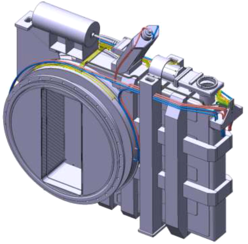
9.1. Fast shutter
The FS [26] is located immediately downstream of the HNB vacuum vessel, just before the AV, and it forms part of the first confinement barrier of the in-vessel radioactive inventory, see figure 11. Its primary purpose is to minimise the transport of contamination from the tokamak to the HNB vessel. The all metal FS has a moving shutter that remains closed at all times except when the NB is being injected into the tokamak. When closed, the leak-rate through the shutter for D2 will be less than 10−2 Pa m3 s−1 (at 293 K) with a pressure differential across the shutter of 2000 Pa. That allows regeneration of the HNB cryopumps with only the FS closed without excessive contamination of the cryopumps in the tokamak vessel. In normal operation the FS will close within 1 s of being commanded to do so, thus minimising contaminant flow from the tokamak to the HNB. The FS will be commanded to open just before injection starts and closed immediately after it finishes, or when a fault event occurs in either the tokamak, such as a disruption, or in the HNB, such as the rupture of a water pipe. When regenerating the HNB cryopumps, the FS is closed more tightly, taking 30 s to close.

Figure 11. Computer generated view of the FS in the closed position viewed from the HNB vessel side.
Download figure:
Standard image High-resolution image9.2. Absolute valve
Each HNB will be equipped with an all metal AV [26] attached to the downstream side of the FS (see figure 12). The AV will be able to isolate the DD, the NB duct and the tokamak vessel from the upstream parts of the HNB, allowing the vessels to be vented to atmospheric pressure independently, if required. When the valve is open, rectangular water cooled shields will automatically be deployed into the valve that will protect the uncooled entrance and exit apertures and the edges of the closure plate from the heat load due to stray beam particles.
The AV is connected to the FS on its upstream side and to the VVPSS box on the downstream side. Both these interfaces consist of similar flanges with a bore diameter of 1.6 m. The flanges are a standard design, with the vacuum sealing between the components achieved with double metal O-rings. The AV, which is supported from the floor of the NB cell (see section 13) by means of a trolley, will be baked to ≈200 °C, which results in significant expansion of the AV. Consequently, the support trolley incorporates elements with sufficient compliance to accommodate that expansion without transferring significant loads across the flanges to the FS. The trolley does not constrain movement in either the axial or transverse directions.
The valve design is a pendulum type valve, with a nominal bore dimension of 1.6 m and an axial length of 0.76 m between the outer faces of the AV casing. The overall width of the valve is 3.12 m with the edge of the rectangular compartment that houses the closure plate when the valve is closed being 2.14 m from the axis of the valve opening. The overall height is ≈3 m. The closure plate actually consists of 2 plates back to back, each carrying metal sealing rings. The interspace between the 2 plates will be pumped with the ITER secondary vacuum system. The valve is rated to sustain a pressure differential of 0.1 MPa across the two plate whilst maintaining a leak rate of <10−7 Pa m3 s−1 (at 293 K), but it can withstand up to 0.2 MPa without sustaining any damage.

Figure 12. Computer generated view of the AV in the closed position viewed from the HNB vessel side.
Download figure:
Standard image High-resolution image9.3. VVPSS box
The VVPSS box [26] is not strictly a component of the NB injector, but it is connected to the AV on its upstream side and the DD on its downstream side, see figure 1, so it is part of the beamline. Figure 13 shows an image of the VVPSS box. The purpose of the VVPSS is to keep the overpressure resulting from an event inside the tokamak vessel, such as the rupture of a water pipe, to <0.15 MPa and the purpose of the VVPSS box is to direct the hot gas entering the NB duct from the tokamak to the very large VVPSS expansion tanks (400 m3).

Figure 13. Computer generated view of the two VVPSS boxes at the end of the VVPSS line that leads to the large VVPSS expansion tanks.
Download figure:
Standard image High-resolution image9.4. Drift duct
The HNB system incorporates a DD [26] located between the NB duct and the VVPSS box which provides a flexible connection between the injector vacuum vessel and the NB duct. The main function of the DD is to accommodate the expected relative displacement due to thermal expansion of ≤50 mm between the VV and the upstream FE components and the injector vacuum vessel. Flexibility is provided by two sets of concentric hydro-formed bellows in a universal joint configuration; the inner diameter of the inner bellows is 2.064 m. The bellows is protected from the re-ionisation heat load (see section 11.3) by an actively water-cooled copper alloy liner (see figure 14).

Figure 14. Computer generated cut-away view of the DD and the DD liner.
Download figure:
Standard image High-resolution image10. NB duct
The NB duct, which is 9 m long (see figure 15), connects the DD to the tokamak, and it forms part of the primary confinement barrier.
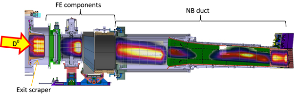
Figure 15. Computer generated cut-away elevation of the FE components and the NB duct for HNB-1. The false colour maps shown on the various components are for power deposited by directly intercepted and re-ionised beam particles. Those are for illustration only; the power density scaling is not the same for all the maps.
Download figure:
Standard image High-resolution imageThe 6 m long part of the NB duct immediately downstream of the DD consists of a rectangular SS duct (2 m high, 1.2 m wide) that forms the vacuum barrier, with a 3 m long, 1.8 m high water cooled Cu panel attached to the inside of the left wall (viewed from the beam source). That panel protects the duct wall from re-ionised beam particles (see section 11.3) that are deflected towards the wall as they pass through the stray magnetic field of ITER. The total power intercepted on the panel is calculated to be ≤0.23 MW with a power density ≤0.3 MW m−2.
The last part of the duct, which is attached to the tokamak vacuum vessel consists of a 1.6 m high, 1 m wide rectangular duct that forms the vacuum wall. Inside of which the 30 T duct liner assembly (NS) is mounted. The NS has to mitigate the neutron damage and heat loads to adjacent components, in particular the superconducting toroidal field coils and the tokamak vacuum vessel. The NS is made of water cooled 316 LN(IG) SS8 , which is up to 200 mm thick. The ratio of steel to water of 9 gives a good attenuation of neutrons from the ITER plasma.
34 actively cooled CuCrZr duct liner panels are installed inside the NS to protect the NS from beam that would otherwise be directly intercepted, and from re-ionised neutrals, see section 11.3.
The NB duct of one of the HNBs (HNB-1) intersects the duct of the adjacent diagnostic NB injector. The square windows in the HNB duct at the intersection are protected by an arrangement of actively cooled CuCrZr cladding to dissipate the heat from the directly intercepted fraction of the diagnostic beam, which is calculated to have power densities of ≤2.2 MW m−2.
If maintenance of the duct liner panels is necessary it must be carried out by remote handling. The limited access, combined with the need to cut and re-weld many of the water connections of the panels, presented severe challenges, which have led to a final design that allows only rather low power counter-injection (<3 MW)9 That arises because for 'counter' injection the direction of the plasma current and all the magnetic fields of ITER will be reversed, which means that the re-ionised beam atoms will follow mirror image of the trajectories in the stray field of ITER during co-injection. That would lead to power deposition in areas of the FE components and the NB duct that are not sufficiently well cooled to cope with the expected power.
11. Calculations of the power deposition on the FE components and the NB duct
Power can be deposited on the FE components and the NB duct by direct interception of beam particles and by re-ionised D0 [27]. Direct interception of the NB by the lateral walls of the FE component and the NB duct is negligible as they are screened by the walls of the neutraliser and RID channels. Direct interception by the top or bottom of the FE components and the NB duct is low due to the height of the FE components and duct and the screening by the cooled scraper at the exit of the HNB vessel (not described here) except when the beam is tilted upwards or downwards to the maximum extent, ±10 mrad10 . More significantly, power can also be deposited on the FE components and the NB duct by beam atoms that have been 're-ionised' by collisions with the background gas; see equation (3) in section 5.1 The re-ionised particles will be deflected onto components downstream of the RID by the stray field from the tokamak. The rate of re-ionisation at a given position along the beam path depends on the reionisation cross sections and the local gas density, and the reionisation power loads depend on the re-ionised particle trajectories after they are created, which is a function of the stray magnetic field from the tokamak along the beam path.
The power deposition is calculated using the BTR code [28], which calculates both the direct interception of the NB and the loads due to the deposition of the re-ionised particles. BTR requires as input the stray magnetic field along the beam path and the initial gas density along the beam path from the exit of the HNB vessel to the entrance to the tokamak.
11.1. Gas density distribution
The Monte Carlo Gas Flow code [29] has been used to calculate the residual gas profiles in the HNB beam lines taking into account all gas sources in the injector and between the injector and the tokamak, which are initially gas from the beam source and the neutraliser, the gas created from the charged beam fraction dumped in the RID, and the gas from the tokamak. In the case of one of HNB-1, the HNB duct and the duct of the adjacent diagnostic NB injector intersect and the gas flow to/from one injector to the other has also to be taken into account. Once injection starts gas is also desorbed from surface directly intercepting beam particles and/or re-ionised particles, which modifies the gas profile, and hence the re-ionisation probability distribution along the beam path. An iterative procedure is used to determine the final gas distribution [27].
11.2. Stray magnetic field from ITER
The stray magnetic field from ITER changes with the operating scenario and also during a pulse with a given operating scenario, and the trajectories of re-ionised particles changes as the magnetic field changes. Therefore it has been necessary to calculate the stray field for all the foreseen operational modes of ITER and for different times during the ITER pulse, e.g. for the tokamak operating with H, He, D and D-T plasmas and for the entire range of foreseen plasma currents (poloidal field configurations) in ITER.
11.3. Re-ionisation losses and power to the HNB beamline components
The trajectories of re-ionised particles depend on the beam species and energy as well as the magnetic and electric fields along the beam path, so the calculated reionisation loss between the entrance of the RID and the entrance to the ITER plasma for both the 1 MeV D0 and 870 keV H0 beams have been made for the various foreseen operational phases of the machine. The losses are typically 7% of the beam leaving the HNB vacuum vessel. For those calculations re-ionisation cross sections 30% higher than those recommended in [30] were assumed in order to accommodate possible inaccuracies in the cross section measurements. Figure 15 shows, for the case of HNB-1, the power density distribution patterns on different components obtained from BTR.
12. HNB vacuum vessel
The HNB injector beam source and the beam line components are contained inside a steel vessel [31]. For convenience of manufacturing and of assembly this vessel is split in two main sections: the BSV and the beam line vessel (BLV). The BLV is 10.3 m long, 4.6 m wide and 3.8 m high with a weight of 47 t. The BSV is 4.9 m long, 5 m wide and 5.3 m high, with a weight of 38 t. The material of both vessels is a low activation SS [31]. The BSV contains the beam source and the BLV contains the beamline components (see figure 1). When completed with the BLV lid, the high-voltage bushing (not described in this paper), and the FE components the assembly constitutes the primary vacuum boundary of ITER and it is part of the ITER first confinement barrier.
The BLV lid can be opened by the remote handling mechanism attached to one of the pillars in the NB cell to allow access for repair or replacement of the beamline components.
The BSV door, which allows the beam source to be repaired or exchanged, is fitted to a frame at the back of the BSV. The only routine servicing operation foreseen is the replacement of the Cs ovens, which will be carried out by remote handling, without opening the BSV door.
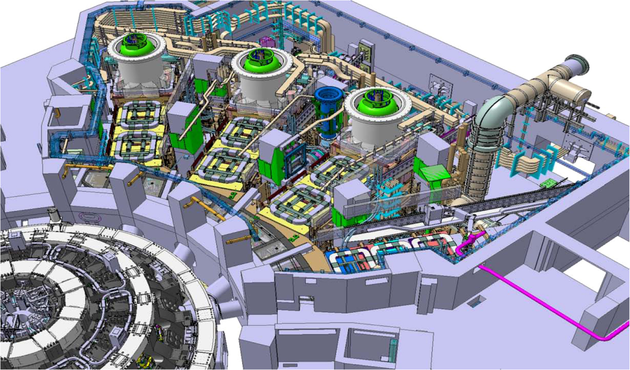
13. NB cell
The HNBs and the Diagnostic NB Injector are to be located in the neutral beam cell (NB cell), which is an 11 000 m3 room in the ITER tokamak building. The NB cell also hosts other systems like the VVPSS boxes and lines, the remote handling systems for the HNBs, all the cooling pipes and cable trays for the HNBs, some diagnostics systems etc. A computer generated view of the NB cell when the maximum of 3 HNBs and the diagnostic injector are installed is shown in figure 16.
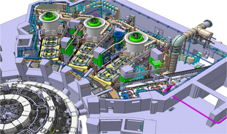
Figure 16. Computer generated view of the NB cell with 3 HNBs and the diagnostic injector installed.
Download figure:
Standard image High-resolution imageThe NB cell is connected to the hot cell building via a dedicated corridor used to evacuate and enter new NB components in case of maintenance [32]. The thickness of the rear wall of the NB has to be sufficient to ensure shielding against the radiation from the tokamak through the HNB ducts, FE components and the HNB vessel.
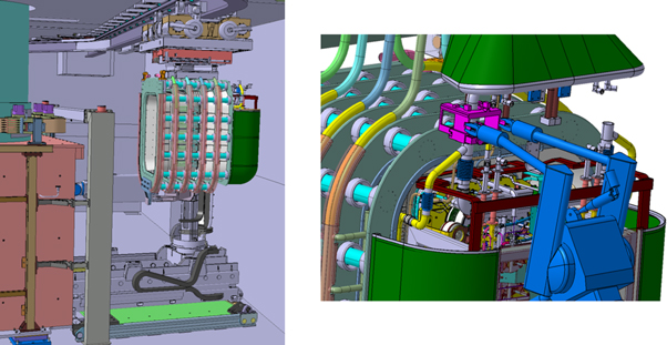
Figure 17. Lhs: beam source being transported by the monorail crane. Rhs: remote handling manipulator cutting (or welding) a water supply pipe of the beam source.
Download figure:
Standard image High-resolution image
14. Remote maintenance
The components of the HNBs have to be maintained using remote handling equipment [33] as the dose rate in the NB cell during maintenance is calculated to be too high to allow human access, and remote maintenance requirements have had a significant impact on the design of the HNBs. The following are some examples of the impact of remote maintenance on the HNB beam source.
- The interfacing features on the beam source are designed such that the maximum weight and the position of the centre of gravity is compatible with transport of the beam source by the monorail crane and to be able to accept all possible loads during the maintenance operation such as an earthquake during transport with the crane (see figure 17 lhs).
- The beam source has many supply lines, for cooling water, RF power, HV voltages, source gas etc, and the design of the beam source must ensure that all connections are accessible, and compliant with, the foreseen remote handling tools. For example the latter restricts the choice of the diameters of the cooling and gas lines as the number of automatic cutting and welding devices is limited. In addition adequate space must be made available around the cutting/welding positions to accommodate the remote handling device (see figure 17 rhs).
- Bolted connections, such as for the bus-bars supplying the current through the PG, must allow space for, and incorporate, trapped bolts and some means of aligning the new and old connections so that the bolts can be successfully tightened.
15. Influence of the nuclear environment of ITER on the design
Nuclear analysis, safety and the licensing process are essential parts of the design process for the ITER HNBs, and they have a significant impact on design choices for the operation, maintenance and decommissioning of the injectors. This imposes constraints on the design, and it means that the design must minimise maintenance, and failure rates must be very low over the 20 years of ITER operations.
The injectors will be maintained by remote handling systems, with some, very limited, hands-on maintenance as the calculated radiation levels in the NB cell will preclude any extensive manned interventions. The design has had to ensure accessibility for all the foreseen remote handling tools and the transport of activated components that have to be replaced from the NB cell to the hot cell building where they will be stored and prepared for disposal.
On ITER, a period of 2 weeks will be imposed before any maintenance operation is carried out in order to allow the decay of short lived radioisotopes. The dose rate after that period is called the shut-down dose rate (SDDR). A detailed model of the injector and its components in the NB cell has been used in the analysis of the radiation levels in the NB cell to ensure that the SDDR in any area where hands-on intervention is needed is below the limit defined by the safety requirements for man access (100 μSv h−1). Many calculations have been necessary to identify the origin of high dose rates and to assess the efficiency of any additional shielding used to reduce those SDDRs. Those analyses resulted in many design changes, for example the activation of the soft iron magnetic shielding around each injector (not discussed in this paper) was found to be one of the main sources of high dose rates. Filling the interspace between the layers of soft iron with 100 mm of polyethylene and covering the external face with 10–25 mm of lead reduced the SDDR in the cell to <100 μSv h−1 in all areas where human access is required.
Radiation can also damage electronics, components and sensors, and corrupt signals. These effects can appear either instantaneously or over a period of time due to an accumulation of ionisation or atomic displacements. This has meant that all electronic etc have been removed from the NB cell.
16. Summary and acknowledgments
Although the principles of a NB injector are straightforward, the engineering and physics of the HNBs is complex, and this paper gives only an overview of the main features of the design of the heating NB of ITER. (Although they are very important for the operation etc of the HNBs, the power supply, water cooling system, magnetic field reduction system and the HV bushing are not described here.)
The design of HNBs has required the contribution of a wide number of scientists and engineers at the ITER Organization; IRFM, CEA, Cadarache, France; Consorzio RFX, Padova, Italy; IPP Garching, Germany; CCFE, Abingdon, UK; the European Domestic Agency (Fusion for Energy), Barcelona, Spain; National Institutes for Quantum and Radiological Science and Technology, Naka, Japan; and the Japanese Domestic Agency of ITER. The authors therefore wish to acknowledge the contributions and thank them for their cooperation.
The views and opinions expressed herein do not necessarily reflect those of the ITER Organization.
Footnotes
- 7
The scraper, which is made of water cooled copper panels, is not described further in this paper.
- 8
316LN(IG) is as 316LN but with additional requirements for ITER, e.g. the cobalt content must be <0.05%.
- 9
Only 'co-injection' is presently planned on ITER, i.e. the injected beam will be parallel to the plasma current at the tangency point. Counter-injection means that the injected beam will be travelling in the opposite direction to the plasma current at the tangency point. The indicated maximum power for counter injection is a conservative limit. The actual allowable power can be determined experimentally on ITER.
- 10
The maximum required tilt of the beam is ±9 mrad, but as the accuracy with which the tilt is determined is ≈±1 mrad, it must be assumed that the beam might actually be tilted by up to ±10 mrad.