


Abstract
We present a method to determine the magnetic configuration of an in-plane magnetized permalloy layer using Fourier transform holography with extended references in an off-normal geometry. We use a narrow slit as an extended holographic reference to record holograms with the sample surface orthogonal to the incident x-ray beam, as well as rotated by 30° and 45° with respect to the beam. To demonstrate the sensitivity of the technique to in-plane magnetization, we present images of flux closed ground states in thin (∼50 nm) permalloy elements, less than 1 μm in lateral size. Images of the in-plane domain pattern which is magnetostatically imprinted into a permalloy film by the stray fields generated by an adjacent Co/Pt multilayer were obtained. It is found that, whilst the domain patterns within the two magnetic layers show a strong resemblance at remanence within a pristine sample, the similarities disappear after the sample is exposed to a saturating magnetic field.
Export citation and abstract BibTeX RIS

Content from this work may be used under the terms of the Creative Commons Attribution-NonCommercial-ShareAlike 3.0 licence. Any further distribution of this work must maintain attribution to the author(s) and the title of the work, journal citation and DOI.
1. Introduction
In recent years, soft x-ray holography has attracted considerable attention for imaging of nanostructured materials, in which element selectivity, high spatial resolution, and independence from optical aberration are beneficial for experimental studies of the material properties. To investigate magnetic materials, Fourier transform holography (FTH), pioneered by Eisebitt et al [1], has been particularly useful for measurements where application of an external magnetic field was required [2–4]. Traditional imaging techniques, such as magnetic force microscopy, are less suited for such measurements as they employ magnetic probes which are influenced by the external field.
The most conventional set-up of FTH for magnetic imaging is optimized for imaging domains with perpendicular magnetization, and is unable to image in-plane magnetization configurations: the magnetic signal, obtained by exploiting the circular dichroism of soft x-ray resonant magnetic scattering (SXRMS) in transmission geometry, is proportional to the projection M·ki of the magnetization M onto the wave vector of the incident light ki. The magnetic signal is thus maximal for perpendicular magnetization and vanishes for in-plane magnetization, when the sample is placed in normal incidence. The in-plane orientation is however a typical configuration for many magnetic thin film structures, such as those containing iron, cobalt, or nickel. Due to demagnetization effects the orientation of the average magnetic moment is normally in the plane of the film. Only highly anisotropic materials, or specifically grown systems (e.g. Co/Pt MLs (multilayers)), exhibit out-of-plane magnetization [5]. In-plane magnetization can be imaged with FTH using a narrow reference hole milled at an inclined angle into a holographic mask [6], however, an extended reference offers a higher flexibility allowing one to vary the incidence angle in situ in order to access both the degree of perpendicular and in-plane components of the magnetization.
In this paper we demonstrate a novel method, based on holography with extended reference by autocorrelation linear differential operator (HERALDO) [7], which extends its application for imaging in-plane magnetized materials. Recent studies using soft x-ray HERALDO [8, 9] have found that holographic measurements with extended references have advantages over the conventional FTH method. In particular, this includes the relative ease of manufacturing the extended objects and a higher intensity throughput without compromising the spatial resolution or signal-to-noise ratio [8]. Here we show that by using HERALDO it is possible to perform holographic measurements of the sample surface when the plane normal is tilted away from the direction of the x-ray beam. By making an angle between the surface normal and the x-ray beam, we obtain a finite SXRMS signal from the in-plane magnetic components [10], thus creating the necessary condition for imaging of the in-plane domain structure.
In the context of magnetoelectronic and applications of multilevel recording devices, FTH has been used to study domain replication in an all-perpendicular anisotropy layered system in which stray fields from a hard magnetic layer induced magnetization in a soft layer [11]. Here we report on high resolution imaging of domain replication in a layered magnetic system, namely [Co/Pt]30/Ta/Py, where the stray fields from the Co/Pt ML magnetostatically imprints an in-plane domain pattern in the permalloy layer. We first demonstrate the technique's sensitivity to in-plane magnetized samples and present images of flux closure domain states in permalloy elements, with lateral sizes below 1 μm. The principles of the technique are then applied to study dipolar interactions in the [Co/Pt]30/Ta/Py multilayered system.
2. Experimental
2.1. Permalloy elements
Samples were made by sputter depositing a 50 nm thick Py film onto the front side of 100 nm thick Si3N4 membranes and protected with a 2 nm Ta capping layer. On the reverse side of each membrane, a 600 nm Au layer was deposited to act as an x-ray opaque mask. A focused ion beam (FIB) was used to pattern a square 1.5 μm field of view (FOV) aperture into the mask, milled down only as far as the membrane. FIB was then used to cut out material from the continuous Py film on the reverse side of the sample so that an isolated 800 nm disc remained within the FOV aperture. The Py element was positioned to one side of the FOV aperture in accordance with the geometry of the experiment to avoid the Au mask blocking soft x-rays from passing through the element when the sample is illuminated and rotated within an x-ray beam. Close to the FOV aperture an extended reference slit was FIB milled through the entire sample mask ensemble. The slit was 3 μm long and ∼40 nm wide.
The measurement set-up is schematically shown in figure 1. Measurements were performed on beamline ID08 at the ESRF using circularly polarized x-rays. The spot size of the x-ray beam was defined by a 20 μm diameter pinhole which is placed upstream from the sample. The pinhole defines the x-ray beam, extracting a small portion with nearly full transverse coherence [12]. The sample was positioned in the x-ray beam and holograms are recorded using a charge-coupled device placed downstream from the sample. A beamstop is used to block the direct x-ray beam to prevent overexposure of the charged coupled device (CCD).
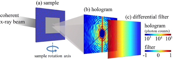
Figure 1. (a) The object field of view (FOV) and reference slit are illuminated by coherent x-rays. (b) The scattered light from the object and reference forms an interference pattern in the far field which is recorded on the CCD camera. (c) A linear differential filter is multiplied by the hologram before performing a Fourier transform to retrieve the reconstructed image. The filter is defined by the directional derivative of the slit and is determined from the hologram by the intense streak, visible in (b).
Download figure:
Standard imageTo examine the magnetization in the Py the plane of the sample was rotated to 30° within the incident beam. The off-normal geometry is similar to the setup, reported by Tieg et al [6], where a narrow hole was milled at an inclined angle into the Au mask which allowed x-rays through a point-like holographic reference source when the sample was rotated within the beam. The photon energy of the x-rays is tuned to the L3 absorption edges of iron (708 eV) and holograms were taken using both helicities of circularly polarized x-rays (see figure 1(b)). To enhance the magnetic contrast and remove the effects of charge scattering, the holograms recorded with left and right circularly polarized x-rays are subtracted from each other [13]. A linear differential filter (see figure 1(c)) is then applied to the difference image, where the linear filter's direction was determined directly from the diffraction pattern by the intense streak visible (as shown in figure 1(b)), which is formed as the x-rays diffract from the edges defined by the reference slit. A Fourier transform is then performed to retrieve the reconstruction. An image of the area within the FOV aperture is reconstructed from either end of the holographic reference slit. Similar to the case of conventional FTH, the reconstruction contains a conjugate image, which shows the same domain structure.
2.2. Interlayer coupling in Co/Pt/NiFe
Measurements of the interlayer coupling in Co/Pt/NiFe were performed on beamline I06 at Diamond Light Source using the same set-up depicted in figure 1. Here a beamstop consisting of a ∼600 μm diameter disc on two ∼50 μm wide crosswires blocks the direct x-ray beam to prevent overexposure of the CCD (Princeton Instruments, 2048 × 2048 pixels of size 13.5 μm) [14].
The magnetic films were sputter deposited onto the front side of the Si3N4 membranes with a thick Au mask deposited on the reverse side. FIB milling was used to pattern a circular 1.5 μm FOV aperture into the mask, and close to the FOV aperture an extended reference slit, 3 μm long and ∼30 nm wide, was fabricated.
The sample-mask arrangement in the rotated geometry is shown in figure 2(a), and demonstrates the passage of the x-ray beam transmitted through the sample. A scanning electron micrograph (SEM) of the viewing aperture and the reference slit is shown in figure 2(b). The experimental setup is depicted in figure 2(c) where the tilt angle α = 45°.
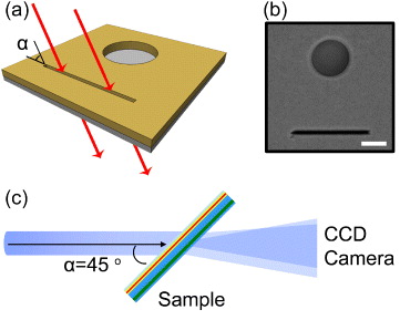
Figure 2. (a) Schematic picture indicating the sample orientation when rotated within the x-ray beam spot. (b) SEM of the reference slit and object aperture viewed from the side of the Au mask (scale bar = 1 μm). (c) Experimental setup with the sample rotated to 45° within the beam spot which makes the x-ray magnetic circular dichroism (XMCD) signal sensitive to the in-plane magnetization.
Download figure:
Standard imageResults are presented for measurements on two magnetic films. Figure 3(a) shows a [Co(0.4 nm)/Pt(1.0 nm)]30 ML film, which was used to demonstrate magnetic HERALDO imaging in transmission geometry [9]. The second film, shown in figure 3(c), was then imaged to investigate coupling effects between a Co/Pt ML and an adjacent permalloy layer (Py = Ni80Fe20) in a [Co(0.4 nm)/Pt(1.0 nm)]30/Ta(8 nm)/Py(5 nm) ML. In the latter case, we use HERALDO in off-normal geometry to image the induced in-plane magnetization. The sample contains a 5 nm Py layer, which is separated from a Co/Pt ML by an 8 nm nonmagnetic Ta spacer. Micromagnetic simulations performed in OOMMF8, reported by Kinane et al [15], suggest that large stray fields generated by the Co/Pt ML just above its surface, influence the magnetic moments in the Py by purely magnetostatic interactions. This means that the Co/Pt ML is capable of imprinting an in-plane domain pattern into the Py layer. By using the chemical selectivity of x-ray imaging we investigate the magnetic contrast of the Py layer and compare this with the domain structure of the Co/Pt ML. To separately examine the magnetization in the Co/Pt ML and Py, the photon energy of the x-rays is tuned to the L3 absorption edges of Co and Fe or Ni respectively. We show that the Py in the as grown samples exhibit an in-plane domain structure which mimics the perpendicular domains of the Co/Pt. However, after the application of a saturating external magnetic field, the remanent state of Py loses its domain structure. In the following discussion we speculate that this might be due to the increased exchange coupled regions that can form after saturation.
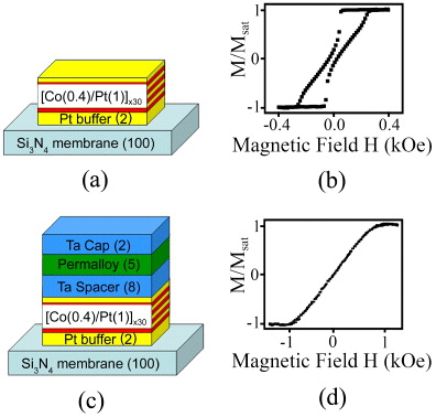
Figure 3. (a) Sample structure of the [Co/Pt]30 ML with corresponding thickness values in nanometers in parentheses. (b) Polar MOKE hysteresis loop of the Co/Pt ML shown in (a). (c) Sample structure of the [Co/Pt]30/Ta/Py ML. Here, stray fields from the Co/Pt ML magnetostatically imprint a domain pattern into the Py layer above. (d) Polar MOKE hysteresis loop from Py in the ML shown in (c).
Download figure:
Standard imageTo preserve the as-deposited state of the samples during the HERALDO imaging, the samples were characterized with polar magneto-optical Kerr effect (MOKE) measurements after completion of the x-ray experiments. Figures 3(b) and (d) show the polar MOKE hysteresis loops of the [Co(0.4 nm)/Pt(1.0 nm)]30 ML and [Co(0.4 nm)/Pt(1.0 nm)]30/Ta(8 nm)/Py(5 nm) ML films, respectively. Figure 3(b) indicates that the Co/Pt ML sample possesses perpendicular magnetic anisotropy, whereas figure 3(d) shows the characteristic field dependence of in-plane magnetic anisotropy. The optical laser probe in the MOKE measurements does not penetrate deep into the sample, therefore the hysteresis loop shown in figure 3(d) is the measured response from only the top Py layer and not the buried Co/Pt ML.
3. Results and discussion
3.1. Permalloy elements
The Py elements were measured in both normal and off-normal geometry with the photon energy of the beam tuned to the Fe L3 absorption edge. Figure 4(a) shows a SEM of the 800 nm disc which is positioned within the square FOV aperture. Figure 4(e) shows a profile schematic of the sample. A reconstruction of the scattering taken at zero applied field, with the sample plane normal to the incident x-ray beam, is shown in figure 4(b). It reveals a faint outline of the square aperture but no structure can be seen because the measurement is sensitive only to the out-of-plane magnetization. The latter, in this case is negligible due to strong demagnetizing fields. Figure 4(c) shows a reconstructed image measured in an external magnetic field of 250 mT applied perpendicular to the sample plane. The magnetization in the disc aligns with the external field and its uniform out-of-plane domain state is revealed.

Figure 4. (a) SEM of an 800 nm disc positioned within a square 1.5 μm FOV aperture (white scale bar = 500 nm). (b) Reconstruction of (a) imaged at remanence with the sample plane normal to the x-ray beam. (c) Uniform magnetic domain state in the Py element when imaged at normal incidence under a 250 mT field applied perpendicular to the film plane. (d) Vortex ground state imaged at remanence with the sample plane rotated to α = 30°. (e) Profile schematic of the FOV aperture. (f) SEM of a device fabricated on a separate equivalent Si3N4 membrane to (a). A 4 μm square region is cut out of the continuous Py film leaving behind a 500 nm square. The region highlighted by the green box contains the 500 nm element which is position off center from a 1.5 μm square FOV aperture which was milled into the Au mask on the reverse side of the sample. A horizontal extended reference slit can be seen below the element. (g) Holographic reconstruction of the permalloy element in (f), imaged at remanence, where α = 30°. The dark regions around the square are artifacts which correlate to areas where the FIB has penetrated through the membrane when the FOV aperture was being milled into the Au mask.
Download figure:
Standard imageThe sample was then rotated away from the beam direction. The position of the reference slit within the sample was placed in such a way that the rotation axis was perpendicular to the long direction of the slit. In this configuration the slit allows the sample to be rotated to a tilt angle, α, while still giving a transmitted beam through the reference and the object FOV aperture. In the measurements, the intensity of SXRMS signal is proportional to the projection of the magnetization vector onto the direction of the incident beam, and so the in-plane magnetization cannot be observed if the sample plane is orthogonal to the beam direction. However, as the sample is rotated to off-normal geometry, the in-plane magnetization acquires a non-zero projection to the beam and thus permits a non-zero contrast detection. Figure 4(d) shows the reconstructed disc imaged at remanence with the sample rotated to α = 30°. Here the vortex ground state of the Py element is revealed. The reconstructions in figures 4(b)–(d) contain unexplained artificial vertical lines, reducing the quality of the images significantly. Additional measurements were also taken with an equivalent sample on beamline I06 at Diamond Light Source which did not suffer from these artifacts. In this case, FIB was employed to cut out a 500 nm square from the continues permalloy film instead of an 800 nm disc. SEM of the element is shown in figure 4(f) with a holographic reconstruction of the element shown in figure 4(g). The sample was imaged with its plane rotated to α = 30° within the beam. The reconstruction reveals a Landau ground state which is typical for Py elements of this size. Some structural artifacts are also visible around the element in the reconstruction which are due to unwanted holes in the Si3N4 where the FIB has pierced through the membrane within the region of the FOV aperture. The exact position of the holes can be seen as black regions in figure 4(f).
3.2. Interlayer coupling in Co/Pt/NiFe
3.2.1. Normal geometry
The measurements of the Co/Pt ML sample were carried out with the photon energy tuned to the Co L3 absorption edge (778 eV). Images were recorded on the full area of the CCD, with an exposure time of 8 s for each frame. A total of 100 accumulations were summed for both helicities of the x-ray beam. The difference between these two holograms is shown in figure 5(a). The reconstructed image which displays four object-reference cross correlations is shown in figure 5(b). Enlargement of one cross correlation is presented, which reveals the magnetic domain structure that is visible through the 1.5 μm FOV aperture that was milled into the opaque gold mask. It shows a typical maze domain pattern that is formed in a Co/Pt ML film at remanence.

Figure 5. (a) A subtraction of the two diffraction pattern images for opposite x-ray helicities. Only the central ∼500 × 500 pixels of the holograms are displayed. The shadow of the beamstop is clearly visible. (b) Real part of the reconstruction. The cross correlations between the ends of the reference slit, and the object are present, their twin images can also be seen (black scale bar = 1 μm). An enlargement of one cross correlation is displayed.
Download figure:
Standard image3.2.2. Off-normal geometry
In the following part of these experiments, the [Co/Pt]30/Ta/Py sample was measured in the off-normal geometry. The normal to the plane was rotated to α = 45°.
Figure 6(a) shows the hologram imaged at the Co L3 edge with the sample surface at normal incidence to the x-ray beam. Figures 6(b) and (c) show the recorded holograms after sample rotation to α = 45° within the beam at the Co L3 and Ni L3 edges, respectively. Each hologram was an accumulation of 100 images for each helicity of the incident light, each frame with an exposure time of 5 s under attenuated beam conditions. Figure 6(d) shows a reconstruction of the hologram in figure 6(a), revealing the domain pattern in the Co/Pt ML when the sample surface is normal to the x-ray beam. The reconstruction contains a region in the form of a circular outline where the magnetization appears to be lost. We believe that this can be due to the Co/Pt ML receiving a high dose of Ga ions during the FIB milling of the FOV aperture [3].

Figure 6. (a) Hologram recorded at the Co L3 edge with the sample surface perpendicular to the x-ray beam. (b) Hologram recorded at the Co L3 edge with the sample surface rotated to 45°. (c) Hologram recorded at the Ni L3 edge with the sample surface rotated to 45°. Only the central ∼500 × 500 pixels of the holograms are displayed. (d) Reconstruction of hologram shown in (a). (e) Reconstruction of the hologram shown in (b). (f) Reconstruction of the hologram shown in (c), revealing the domain structure in the Py layer closely matching the domain pattern in the Co/Pt ML. An overlay of the domain boundaries at the Co edge is highlighted by the blue curves. The red dot on the reconstructions indicates the same spatial location on each (white scale bar = 500 nm). (g) Reconstructed image of the sample recorded at the Fe L3 edge with the sample surface perpendicular to the x-ray beam. A saturating magnetic field was applied and the sample was re-imaged at remanence. (h) Reconstructed images of a hologram recorded at the Co L3 edge at remanence, after a saturating magnetic field was applied. Out-of-plane striped domains in the Co/Pt can be seen. (i) Reconstructed image of a hologram recorded at remanence at the Ni L3 edge after the saturating magnetic field was applied. This shows the in-plane domain structure in Py after saturation.
Download figure:
Standard imageFigure 6(e) shows a reconstruction of the hologram at the same absorption edge when the sample was rotated to 45°. The strength of the signal in this case is reduced by ∼30% given the reduced projection component of the magnetization to the beam direction. At this angle some part of the FOV is also blocked by the walls of the aperture. The exposed part shows a domain structure revealing the same configuration as in the case of the normal (perpendicular) orientation. For comparison, a spatial point in the domain pattern at α = 90° and 45° is marked by red dots, as indicated in figures 6(d)–(f). Figure 6(f) shows a reconstruction of the hologram recorded at the Ni edge. When compared with the image of Co at 45°, the domain structure of Ni seem to repeat the same configuration, suggesting that the pattern is influenced by the structure of Co/Pt ML. The magnetic contrast of the Ni pattern was, however, found to be significantly reduced (compared to that of the Co edge), correlating with the reduced amount (and the magnetization value) of Ni being probed. We note that the demonstrated image is given for the sample that had not been exposed to large magnetic fields, so the domain structure is induced in the Py layer in its as-deposited state, in which the remanent magnetic structure is mainly determined by the local structure of the material, and on average, should show no preferred magnetized direction within the plane. We also note that the resulting domain structure is due to the in-plane magnetization components, and not the perpendicular ones: because of the strong demagnetizing effects (and as verified by the MOKE loops in figure 3(d)) it would require a much larger field to produce an out-of plane component. To verify this, a hologram of the same sample was recorded for the perpendicular orientation at the Ni L3 and Fe L3 edges. Unfortunately the first measurement did not provide a consistent reconstruction. The measurement at the Fe L3 edge (figure 6(g)) showed a uniform contrast indicating a zero or uniform component of magnetization in this direction, however we do not have a measurement at 45° for this edge to provide a direct comparison of the signals for in-plane and out-of-plane orientations of the field.
We find the result of figure 6(f) rather surprising and we suggest here the following qualitative explanation. The exact mimicking of the CoPt domains initially suggests the formation of a perpendicular component in the Py layer, which can naturally follow the perpendicular demagnetizing field from the 'up' and 'down' moments in the Co/Pt ML. The perpendicular component in the Py layer is however suppressed by the demagnetizing field, and thus cannot produce any significant contribution to the observed magnetic contrast. Our perpendicular measurements confirm this suggestion (figure 6(g)). The contrast in figure 6(f) can thus only arise from the in-plane components of Py. One possibility is that this originates from the in-plane dipolar field above the Co/Pt domain walls, however the resultant domain structure in this case would not mimic the domains formed in Co/Pt. The only way one can explain the mimicking, if this pattern is not a stable configuration, is that it has its origin in the growth process. We believe that the in-plane structure may arise during the deposition process and stay unaffected until a reasonably large field is applied. Figure 7 explains schematically our suggestion. When the layer is formed—typically starting from nanoscopic islands or a very thin layer—the local moments in the 'islands' (or the monatomic layer) follow the direction of the perpendicular demagnetizing field from Co/Pt domains (figure 7(a)). At this point the demagnetizing effect of the Py is negligible (one may also suggest a contribution of the perpendicular surface anisotropy, which also aids in providing the out-of-plane component). Once the space between islands is being filled (or the layer gets thicker) the demagnetizing field from Py increases and tends to incline the moments toward the plane (figure 7(b)). At this point the moments with 'up' directions are already coupled via exchange and form domains mimicking 'up' domains in Co/Pt. A similar situation would be expected from the moments with 'down' direction. When the moments are tilted toward the plane, they remain in the same configuration. This configuration is not energetically ideal, but stable enough to exist until an external field is applied. It is also surprising that the orientation of magnetization in different domains of the same sign (e.g. all white) seems to follow the same preferred orientation in the film plane. If the plane was completely isotropic then the moments in different domains would be free to relax in any direction, thus resulting in different magnetic contrasts. Yet the observed Py pattern is nearly identical to that from in CoPt (see figure 6(f)), indicating that the moments in both 'white' and 'black' domains follow a uniaxial direction which has a non-zero projection onto the x-ray wave vector. We speculate that the preferred direction can be induced during the growth by the weak magnetic field present in the sputtering process. Magnetron plasma systems typically require fields to maintain plasma or reduce the electron acceleration during the sputtering deposition. This field, typically below 10–50 G, is sufficient to influence magnetization on a local scale. So as a result, when the thickness of the layer is increased and the magnetic moments of Py start getting inclined to the plane they may preferentially settle to the direction of the field. At the same time the dipolar coupling between the domains and the exchange interaction within domains will maintain the initially induced configuration. This structure is however unstable, and after applying a saturating magnetic field, the domain pattern is erased and cannot be recovered. In the next section we discuss the results of imaging after application of a saturating field.
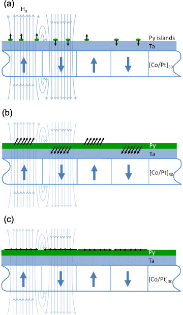
Figure 7. Qualitative explanation of domain mimicking. (a) During the deposition of the Py film onto the stack, nanoscopic islands (or a very thin layer) will initially form. The local moments in the 'islands' (or the monatomic layer) follow the direction of the perpendicular demagnetizing field (shown by the pale blue lines), Hd, from Co/Pt domains. At this point the demagnetizing effect of the permalloy is negligible. (b) During the next stages of the deposition process the spaces between the islands fill (or the layer becomes thicker). The demagnetizing field from the Py increases and tends to incline the moments toward the plane. Here, the moments with 'up' directions are already exchange coupled and form domains mimicking 'up' domains in Co/Pt. Similarly the moments with an initial 'down' direction mimic the 'down' domains in the Co/Pt. As the moments are tilted toward the plane they remain in the same configuration. (c) The final magnetic state in the permalloy layer consists of in-plane magnetized domains.
Download figure:
Standard image3.2.3. Applied magnetic field
Further imaging of the sample was carried out in an applied magnetic field. A saturating field of 250 mT was applied perpendicular to the beam whilst the sample was kept at 45°, providing out- and in-plane field components of 176 mT. Figures 6(h) and (i) show the domain configurations after the sample, remaining at α = 45°, was reimaged at zero field after being exposed to the saturating field. They show similar object FOV and reference slit on a different part of the sample at the Co and Ni L3 edges, respectively. The magnetic configuration in the Co/Pt ML shows a maze domain structure which was found before applying the field, however, the presence of a magnetic configuration was absent at the Ni edge. The image shows a uniform intensity, which is interpreted as a constant level of magnetization. We speculate that after a saturating external field is applied, the domain structure is dominated by the larger domains formed due to the local exchange coupling within the Py layer. In the pristine state, the remanent magnetization is formed by small, uncorrelated regions, that are susceptible to local fields and tend to couple via exchange interaction as the preferred orientation becomes similar in neighboring domains. In this state, it is possible for demagnetizing fields from Co/Pt ML to induce a similar structure in Py layer. Once a saturating field is applied, larger domains form in Py layer that are now more difficult to decouple. Returning to zero field still produces an overall zero remanence (the hysteresis is negligible), however, the size of the domains is now of macroscopic size and unlikely to be verifiable, unless the domain wall passes exactly in the FOV of the sample.
4. Summary
In conclusion, we have demonstrated magnetic HERALDO imaging and implemented the technique at off-normal incidence to directly image the domain structure of different magnetic layers in a [Co/Pt]30/Ta/Py ML. We demonstrated that, when applied to magnetic systems, off-normal magnetic HERALDO imaging provides sensitivity to in-plane magnetization with the magnetic contrast obtained via SXRMS. We have presented images of flux closure ground states in permalloy elements less than 1 μm in lateral size. Using an example of a complex magnetic system comprising of two types of magnetic components, perpendicular and in-plane, we demonstrated that both components can be resolved. In particular, we obtained images of both the perpendicular domain structure within the Co/Pt ML, and the in-plane structure of the Py layer. The Py structure mimics the spatial domains in Co, when the sample is in the as-deposited state. However, after exposing the sample to an applied magnetic field, the induced in-plane structure of Py is inhibited. It is suggested that once saturated, the Py layer forms its own domain structure which remains dominant within the layer in zero field.
Acknowledgments
We gratefully acknowledge the assistance of Paul S Keatley with the polar MOKE measurements and thank the Centre for Material Physics and Chemistry (CMPC) of the Science and Technology Facilities Council (STFC), UK and the Engineering and Physical Sciences Research Council (EPSRC), UK for funding.
Footnotes
- 8
OOMMF, Object Oriented Micromagnetic Framework, http://math.nist.gov/oommf.