

Abstract
We report transport, electromechanical, and structural properties of single core MgB2/Fe wire produced using a new fabrication method, called designed internal Mg diffusion (IMD) process, which relies on the use of non-stoichiometric Mg + B pellets with excess Mg in place of a central Mg rod used in the standard IMD method. Structural analysis revealed the successful formation of a porous MgB2 structure in the center and a dense circular MgB2 layer surrounding this structure in the designed-IMD wire. Fast transport I–V measurements showed that the designed IMD method increased engineering critical current density (Je) up to twice that of the IMD wires in self-field. The central porous MgB2 structure shared the applied current and indirectly behaved as an internal stabilizer against quench damage at high applied currents.
Export citation and abstract BibTeX RIS
1. Introduction
MgB2 with 39 K critical temperature is a suitable material for the realization of cryogen-free magnetic resonance imaging (MRI) magnets, as it can be wired in a viable metallic sheath and operated above 4.2 K. However, the operating cost of MgB2 wire should be lowered compared to the niobium–titanium (NbTi), commonly used in commercial MRI systems, and therefore LHe-free cryocooling systems are needed to be developed for the realization of MgB2 MRI magnets [1–5]. Another requirement for the construction of a large MgB2 magnet is that kilometers of superconducting wire must be produced. The in situ MgB2 wires produced by the powder-in-tube (PIT) method, in which the magnesium and boron (Mg + B) powder mixture is encased in a suitable metallic tube, are now fabricated in km length scales [6, 7]. The internal magnesium diffusion method, which enables a significantly higher in-field critical current density (Jc) than the PIT method, is more advantageous in terms of using MgB2 instead of NbTi in the MRI magnet [8–11]. However, the Je in internal Mg diffusion (IMD) wires is lower than that of PIT wires because a large hole is formed in the center of IMD wire due to diffusion of the central Mg rod into the surrounding boron during heat treatment [11–16]. The core uniformity is also challenging in the production of long IMD wires due to the variations in the packing density of boron powder along the IMD wire, leading to changes in the superconducting properties after heat treatment. Therefore, improving the longitudinal uniformity and Je in IMD wires is essential for large-scale applications [11, 16–21].
Superconducting joining is required to operate MRI magnets in permanent current mode because an ultra-stable magnetic field with a decay rate of <0.1 ppm h−1 is required for high resolution images. MRI magnet construction using a superconducting MgB2 wire is conceivable by joining individual coils in series but a very low joint resistance is needed in terms of heat generation [22, 23]. Recent studies have shown that a joint resistance as low as 10−15 Ω is achieved in the joining of unreacted MgB2 wires [4, 24–27]. However, reliable superconducting joints have not yet been fully optimized, especially for reacted MgB2 wires [11, 28–30].
In this study, standard-IMD, powder-IMD, and designed-IMD wires were fabricated using a multi-pass cold drawing process at room temperature [31]. Mg/B pellets with excess Mg and Mg in powder form were used in place of a central Mg rod in the designed and powder-IMD wires, respectively. In this way, the role of Mg in different forms was explored in terms of internal diffusion of Mg in IMD wires. For designed-IMD wire, a central porous MgB2 structure with a surrounding dense MgB2 layer was formed to take advantage of both the Je of PIT and the excellent Jc of IMD processes. The central porous MgB2 in the designed-IMD wire is also advantageous in terms of superconducting joining because it provides a larger MgB2 contact surface than that of the standard-IMD wire having a large hole.
Additionally, there are not many studies on the electromechanical properties of single core IMD MgB2 wires [32–35]. In this study, degradation in critical current (Ic) as a function of bending diameter was studied for different wire pieces.
2. Experimental details
The wire, called S1, was produced using the designed-IMD method with the filling steps mentioned below. First, amorphous nano-boron powder (98% purity, <250 nm size) was filled into the space between the pre-centered 6.6 mm diameter steel rod and the iron tube by hand compression. The steel rod was used as a guide to obtain a boron layer at the inner surface of the iron (Fe) tube. After filling the Fe tube with boron powder, the steel rod was gently pulled out. Mg/B pellets with 6.4 mm diameter were prepared by pressing Mg0.052 + B0.039 powder mixture (95%–97%, <1 μm, semi-amorphous boron; 99%, 325 mesh magnesium) under pressure of 305 MPa. Finally, the pellets were placed one by one into the central hole left behind by the removal of the steel rod (see figure 1). S2 is a standard-IMD wire in which the Mg rod with 4.6 mm diameter was fixed in the center of the Fe tube and the amorphous nano-boron powder was filled into the empty region between the Mg rod and the Fe tube by hand pressing.
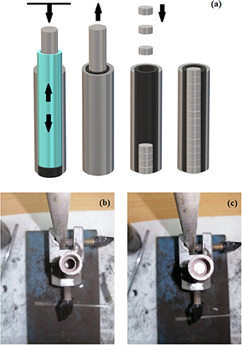
Figure 1. (a) Schematic and (b), (c) real images for in situ designed IMD filling process.
Download figure:
Standard image High-resolution imageS3 wire was produced using the magnesium powder method [36], in which Mg powder was used instead of Mg rod. The diameter of the space in the center for filling the Mg powder was again 6.4 mm. Through this arrangement, we achieved MgB2 ring layer thicknesses, which were not very different in S1 and S3 after the reaction as represented in figures 2(a) and (e), respectively. Mg powder was not compressed in order not to distort the surrounding boron layer. The initial iron tubes with outer/inner diameter 12/9 mm were used for all samples. All composites were brought to round wire form by cold drawing from 12 to 0.81 mm with several intermediate heat treatments. The wire pieces of 300 mm length were synthesized at 650 °C (5 °C min−1 ramping rate) for 4 h under argon atmosphere to form MgB2 phase (see figure 2). The fact that the wire pieces were 300 mm long and their ends were closed by pressing prevented the loss of magnesium from the wire ends during the heat treatment. Pre-tested reacted straight wire samples of 25 mm length were bent to a certain bending diameter at room temperature, and degradation in Ic was surveyed by current–voltage measurements on released wires at 25 K using a gas contact closed-cycle cryostat (Cryo-Industries) system with a superconducting magnet up to 7 T [37]. The straight wire pieces were bent to different diameters of 350, 300, 250, 200, 175, 150, 125 and 100 mm for all samples.
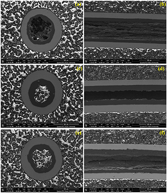
Figure 2. SEM images for cross-sectional and longitudinal views of (a), (b) S1, (c), (d) S2, and (e), (f) S3 samples, after synthesis.
Download figure:
Standard image High-resolution imageThe fast I–V measurements in self-field were performed on samples approximately 25 mm long in vacuum, cooled by conduction from both current contacts, which were thermally in contact (and electrically insulated) to a copper block anchored to the second stage of a cryocooler. A thermometer was attached to one of the current contacts, a heater on the copper block and a Lakeshore temperature controller were used to control the temperature of the sample. Current linear ramps for 1 s were used to avoid heating the sample during the measurements.
The in-field critical current (Ic) measurements were made at the Institute of Low Temperatures and Structural Bdań PAN in Wrocław. The Ic measurements in liquid helium were made by using Bitter magnet of 14 T and a direct current (DC) source from 0 to 150 A. On the other hand, the measurements of Ic at 20 K and 25 K were made using the Oxford Instruments Susceptometer, e.g. temperature range 2 K–350 K, magnetic fields up to 9 T and DC range from 0 to 150 A. All Ic measurements were made in a perpendicular magnetic field. The critical currents were determined on the basis of the 1 µm cm−1 criterion.
A scanning electron microscope (FEI, Quanta FEG 250) with the accelerating voltage of 30 kV was used to investigate the surface morphology of the Fe/MgB2 wires.
3. Results
3.1. Transport measurements with fast current ramp in self-field
Figures 3(a)–(c) show the transport measurement results for S1, S2, and S3 samples at various temperatures above 30 K. The Ic values in the self-field were determined from the I–V characteristic curves using 1 µV cm−1 criterion. In the experiments, we first set the temperature to 36 K. After the temperature stabilized, the maximum current of the ramps was gradually increased to reach the Ic value. Later, the temperature was set to a lower value and the process was repeated. In the case of sample S1, although the voltage increases very sharply after achieving the Ic value at higher currents (see figure 3(a)), no damage is observed and this sample had the same Ic value in repeated measurements at all temperatures. However, for the other samples the behavior at high currents is different. An example of this effect is shown in figure 3(b), corresponding to sample S3 at 34 K. In the first ramp up to 90 A, not appreciable voltage (above the noise level) was observed (curve blue in the figure). Nevertheless, at high applied currents, the quenching effect caused the current not to increase any further and reflected itself as current oscillations through the end of current ramping. Beyond that, the S3 sample was completely damaged when it was re-measured at 34 K. The obtained results suggested that the quench triggered outside the zone between the voltage taps. A similar, but relatively weak, quenching effect on Ic was also observed for S2 sample at 32 K. In our opinion, the quench occurs either at the ends of the current contacts or in the current contact itself and propagates to the rest of the sample. Although the current was ramped in 1 s, quench was not tolerated, and thus S2 and S3 samples were damaged at high applied currents.
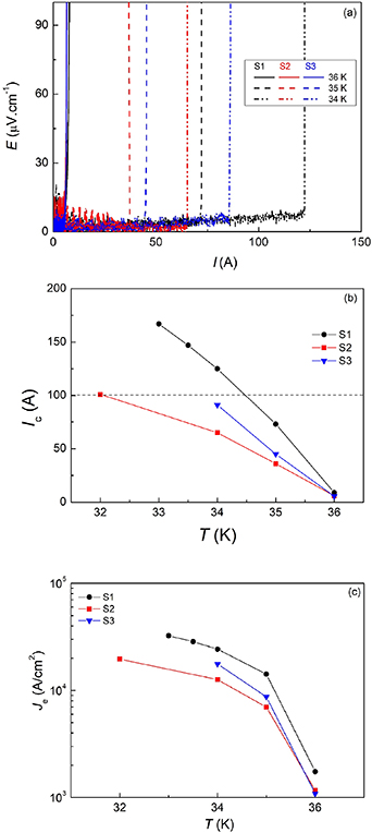
Figure 3. (a) Electric field–current (E–I) characteristics for S1, S2, and S3 wires in self-field. (b) Temperature dependent transport critical current (Ic) behavior of S1, S2, and S3 samples in self field. (c) Je–T curves for all samples. In figure 3(a), solid, dashed, and dashed-dot lines represent the 36 K, 35 K, and 34 K, respectively.
Download figure:
Standard image High-resolution imageThe results indicated that Fe-sheathed IMD wires had quenched even below their critical currents when they were not properly stabilized (see figure 4). On the other hand, the designed IMD wire allowed applying relatively higher currents without a direct quench damage and had a higher Je than that of the IMD wires in self-field as shown in figures 3(b) and (c). It seems that, at least for these three wires, IMD wires are more prone to quenching as previously stated in the study of Kováč et al [38]. We suggest that the low thermal stability of of Fe/MgB2 IMD wire could be improved by IMD/PIT hybridization against the negative effect of quench power. This is because we consider that the applied current is shared between the central porous MgB2 core and dense MgB2 layer in S1 and the low thermal stability of iron is somewhat compensated in this way.
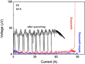
Figure 4. Quench development for S3 wire at 34 K in self-field.
Download figure:
Standard image High-resolution image3.2. Direct current (DC) transport measurements under external magnetic field
DC transport measurements for Ic were made at 4.2 K, 20 K, and 25 K under various external magnetic fields for all samples as shown in figure 5. We observed that samples S1 and S3 had similar critical currents at 20 K and 25 K, although Ic values in moderate fields (about 4–6 T) were slightly higher for S1 than S3. However, the S2 sample presented the highest Ic values at 4.2 K among the analyzed samples, although very close to those of the S1 wire. In contrast, S2 had the lowest values at 25 K in all fields. Therefore, we observed that, generally, S1 sample was only capable of carrying as much current as S2 and S3 wires under external magnetic fields. It seems that the external field suppresses the superconductivity in the porous MgB2 core of S1, and thus the current is not shared by the central core and is carried only by the thin MgB2 layer of S1, resulting with Ic value close to that of S2 and S3 wires. We consider that a better high field pinning can be achieved in the porous MgB2 core of S1 with a combination of some other methods such as carbon doping. For instance, our previous study showed that Mg could form a layered (lamellar) structure that allows Jc and Birr to be increased [39].

Figure 5. Ic vs B characteristics for S1, S2, and S3 wires.
Download figure:
Standard image High-resolution imageThe quench may be initiated due to the interface resistance of iron-boride phases between the Fe sheath and core in all wires. The highly reactive nano amorphous boron reacted with iron sheath even at relatively low synthesis temperatures of 650 °C [40]. This is because quenching became more pronounced and limits the application of higher currents to our thin wires in all temperatures, when the DC was not transferred fast to the samples.
3.3. Electromechanical (bending strain) measurements
Transport measurements for Ic of straight and bent wires were performed at 25 K under magnetic fields of 4.8, 5.0 and 4.7 T for S1, S2, and S3 wire pieces, respectively. The magnetic fields were adjusted to equalize the Ic values of the samples [37]. Figure 6 shows the normalized critical currents (Ic/
Ic0) as a function of bending strain ( B), calculated by using the formula B = ϕ/d where ϕ is the wire diameter (0.81 mm) and d is the bending diameter ranging from 100 to 350 mm. Ic0 and Ic are the critical currents of the wires in their straight and bent forms, respectively. The critical current measurements were made on different reacted short wire pieces of 25 mm length taken from different parts of the wires in order to check the homogeneity of the wires. We found that bending was tolerated up to 0.46% for S1 and S2 samples and 0.40% for S3 sample.

Figure 6. Normalized current vs bending strain tolerance characteristics for S1, S2, and S3 wires. The maximum applied current is 1 A. Each reacted straight wire piece was bent to a certain bending diameter at room temperature.
Download figure:
Standard image High-resolution imageFigures 7(a)–(f) show the optical microscopy images of bent S1, S2, and S3 samples. The bending diameters at which the first breaks occur are 150 mm for S1 and S2 samples and 175 mm for S3 sample. The longitudinal views of the wire samples in figures 7(a), (c), and (e) reveal the appearance of the structural micro cracks causing the initial degradation in Ic. The crack formation occurred in three places on the stretched side of the core in each sample, where the compressed side did not yield any crack. Figures 7(a), (c) and (e) show the thickness values for the dense MgB2 layer (orange color) and figures 7(b), (d) and (f) reveal the width of the cracks in each sample. The porous MgB2 structure formed in the center of the S1 wire cannot be seen with the optical microscopy, but this structure is exhibited in the SEM images given in figures 2(a) and (b). S3 has an inhomogeneous core structure and the core thickness is relatively smaller than that of the S2 sample. We consider that the MgB2 core thickness is a critical factor in IMD wires. This is because a thick MgB2 core of S2 provided a better bending strain tolerance than that of S3, but wider cracks were formed in the S2 sample, which has the thickest MgB2 core, than in the S1 and S3 samples. S3, with a large mid-cavity, contains significant amounts of unreacted Mg near the interior of the MgB2 core. This can be considered as the cause of the longitudinal non-uniformity in S3 wire and formation of longitudinal cracks under bending as seen in figure 7(e). On the other hand, S1 sample has a fairly good longitudinal uniformity although it has the thinnest MgB2 ring layer among the samples. It seems that the complete diffusion of Mg towards the surrounding nano boron layer in S1 was achieved by using semi-crystalline boron powder, having low reactivity with Mg, in the center [41, 42].
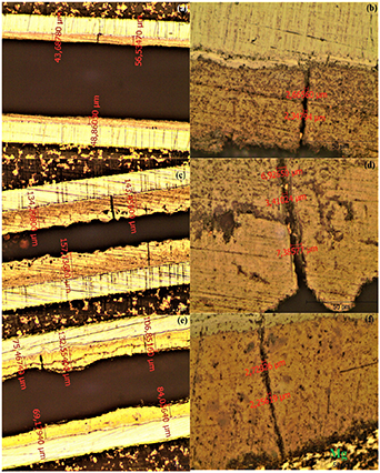
Figure 7. Optical microscopy images for 5× and 50× magnifications taken from (a), (b) S1, (c), (d) S2, and (e), (f) S3 wires.
Download figure:
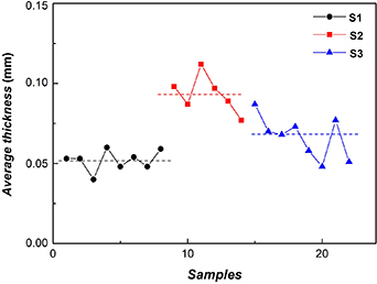
Standard image High-resolution imageFigure 8 shows the average MgB2 layer thickness values obtained from various S1, S2 and S3 samples. MgB2 core thicknesses were determined by averaging the thicknesses measured from at least ten different locations along the lateral MgB2 cores. It was found that S2 had the largest MgB2 layer with thickness of 93 µm, while S1 had the thinnest layer about 50 µm on average. The designed IMD method enabled to obtain a more uniform MgB2 core than IMD wires as seen in figure 8. Apparently, the variations in MgB2 layer thickness are not totally avoidable as the Mg metal in powder or rod form was being elongated through the boron powder.
Figure 8. Average MgB2 core thicknesses for various S1, S2, and S3 wires.
Download figure:
Standard image High-resolution image
4. Conclusions
In this study, a new type of single-core IMD MgB2/Fe wire with a diameter of 0.81 mm was produced and experimentally characterized. In this new proposed method, Mg/B pellets with excess Mg were used in place of the central Mg rod normally used in standard IMD method. Structural analysis demonstrated the successful fabrication of the designed-IMD wire (S1) characterized by a uniform and dense annular MgB2 layer around a central porous MgB2 core. By comparison, a standard-IMD wire (S2) and a powder-IMD wire (S3), in which Mg powder was used instead of Mg rod, were also fabricated and characterized. The normalized Ic vs bending strain measurement results revealed that the designed-IMD wire had the critical bending stress tolerance of 0.46% which is the same as the S2 wire and is better than that of S3. Here, S2 wire has an MgB2 layer thickness of about 2.5 times thicker than that of the S1. According to the fast I–V measurement results, S1 carried the highest current without quenching among the samples and had an Ic value of 167 A at 33 K in the self-field. The porous MgB2 structure in S1 core shares the applied current, increasing Je compared to S2 and S3. In this way, the porous MgB2 structure in S1 core also indirectly acts as a stabilizer against the quench damage. It was observed that S2 and S3 IMD wires were more prone to quench and needed to be properly stabilized due to a lower thermal stability of Fe sheath. More importantly, the formation of resistive iron boride (FeB, Fe2B) phases became a more critical issue in terms of quenching, when the DC was not transferred fast enough to the samples. We consider that the designed IMD method deserves further investigations, especially for multifilament IMD wires and their joints, as it offers the advantages of uniformity, parametrization (i.e., the choice precursor material, carbon doping, MgB2 layering size etc) and higher Je for IMD wires.
Acknowledgments
This work is funded by the Scientific and Technological Research Council of Turkey (TUBITAK) research project with Grant No. 119M288. E M acknowledges the financial support from MCIN/AEI/10.13039/501100011033 (Project PID2020-113034RB-I00) and from Gobierno de Aragón 'Construyendo Europa desde Aragón' (research group T54_20R). The use of Servicio General de Apoyo a la Investigación-SAI (Universidad de Zaragoza) is also acknowledged.