
Abstract
Relativistically intense laser light interacting with solid density targets can accelerate protons to multi-MeV energies via the target normal sheath acceleration process. The use of hollow hemisphere targets with a hollow conical region to focus protons of selected energies, for applications such as isochoric heating of matter and for the fast ignition approach to inertial confinement fusion, is explored for laser intensity  Wcm−2. Specifically, the effects of having the cone tip open or closed is investigated experimentally and via a programme of scaled particle-in-cell simulations. The open cone configuration is found to result in proton focusing in the energy range of 9 to 24 MeV, and produce an annular profile for higher energy components, up to 55 MeV, while the spatial distribution of lower energy components remains unchanged. By contrast, for the closed cone case, the focusing effect is diminished by the fields present on the inner wall of the cone tip. Simulations reveal that strong electrostatic and magnetic fields present on the inner surfaces of the target induce the focusing effect with the open cone, but also result in proton divergence in the case of the closed cone. Additionally, the simulations demonstrate the possibility to tailor the cone geometry to select the energy range over which the focusing occurs.
Export citation and abstract BibTeX RIS

Original content from this work may be used under the terms of the Creative Commons Attribution 4.0 license. Any further distribution of this work must maintain attribution to the author(s) and the title of the work, journal citation and DOI.
1. Introduction
The acceleration of protons to energies in the tens-of-MeV range is routinely achieved at many high power laser facilities [1, 2], and energies in the range of 100 MeV have been demonstrated [3]. The intrinsic properties of these beams of protons, such as their short bunch duration and high flux, make them potentially useful for a range of applications, including medical oncology [4–7], industrial processes [8–10], isochoric and volumetric heating of matter [11], as well as a driver of the fast ignition approach to inertial confinement fusion [12]. Their heavier mass, compared with electrons, also make them less susceptible to fast growing plasma instabilities. This makes laser-driven protons particularly well-suited for fast ignition (often referred to as proton fast ignition, PFI) [13, 14], which requires sufficient energy to be delivered to ignite a compressed deuterium–tritium plasma on a timescale shorter than the fuel disassembly time.
Several laser-driven ion acceleration mechanisms have been explored, with target normal sheath acceleration (TNSA) [15] being the most studied and robust. Protons with energy up to 85 MeV have been attributed to the TNSA scheme [16], and high laser-to-proton energy conversion efficiencies of the order of 10% have been demonstrated [17], which amounts to tens-of-Joules of proton pulse energy for a laser drive pulse with hundreds-of-Joules. For PFI, control of the spatial profile of the proton beam, and thus the energy deposition profile within the plasma, along with sufficient laser energy conversion into higher energy protons is required to provide the necessary flux to achieve ignition. Higher flux beams also greatly enhance the usefulness of these sources for the creation of material in states of warm dense matter because it facilitates very rapid energy deposition and thus isochoric heating [18]. Whereas typically TNSA studies involve thin planar foils from which a diverging proton beam is produced, it has previously been shown that some degree of proton beam focusing can be achieved by using a curved, hollow hemispherical target such that the protons leave the source region directed towards a central axis [11, 19–21]. The degree of focusing achieved by this approach is, however, limited by Coulomb repulsion within the beam [22], which increases with charge density [23, 24].
The effects of Coulomb repulsion can in principle be countered by using an opposing radially-directed focusing field acting on the protons as they propagate from the source region. The fast electrons that are produced at the focus of the laser pulse and spread laterally along the surfaces of the target induce strong transient electric fields [25, 26] that can be used for post-acceleration or collimation of the proton beam. The use of hollow microspheres as targets for staged laser-driven proton acceleration has been demonstrated [27] and a helical coil attached to the target has been used to induce a propagating field resulting in post-acceleration and collimation the beam of laser-accelerated protons over extended lengths [28]. In the context of PFI and isochoric heating applications, a hemisphere-cone geometry has been explored [23]. The fast electrons establish a transient radial focusing field within a cone region attached to the laser-irradiated hemisphere, which acts on the protons travelling within it [29–32]. Recently, focusing has also been reported using a closed conical target (irradiated by the 1.25 kJ, 10 ps Omega EP laser with a moderate laser intensity of  Wcm−2) [33], with focusing diagnosed via copper K
 emission from a secondary foil target at the end of the cone. For a PFI scenario, a conical structure has the additional advantage of protecting the proton source region (within the hollow hemisphere) from the compressed plasma fuel, in particular when using a closed geometry. Investigation of the effects of the conical geometry on the properties of the resultant beam of protons is important to assess the potential use of targets of this type for applications such as PFI.
In this article, the influence of the cone section of a hemisphere-cone target on proton beam focusing is explored experimentally and numerically, including the effects of having the cone tip open and closed. Focusing is observed for protons in the energy range 9–24 MeV, and higher energy protons exhibit an annular profile, for an open cone scenario. By contrast, these features are not observed for the case of closed cone irradiated with similar laser pulse parameters. Scaled 2D particle-in-cell (PIC) simulations reveal that transient radial electric fields produced on the inner surface of the cone act to focus protons in a specific energy range defined by their time of transit through the target when the radial fields are at their maximum strength. In the closed cone scenario, electric and magnetic fields formed on the inner surface of the end-wall act to decelerate the protons and induce beam divergence. The simulations also indicate that the focused energy range can be adjusted by varying the length and opening angle of the conical region of the target. This approach could prove useful for focusing and increasing proton flux at selected energies for applications such as isochoric heating of materials and PFI.
2. Experiment
The experiment was performed using the Orion laser [34]. The laser beam was p-polarised, with wavelength  1.053 µm. Laser pulses with energy
  J were focused using an
  off-axis parabola, to a spot size of
  µm (full width at half maximum, FWHM) with pulse duration
  ps, giving a peak intensity of IL =
  Wcm−2 (normalised potential
  ). The pulses were focused onto the convex side of a gold (Au) hemispherical target of thickness
  µm, 600 µm radius of curvature. The laser contrast was 1010 up to 1 ns prior to the peak of the pulse and 106 up to 250 ps prior to peak [34, 35]. For some targets, an open or closed-tip Au cone, with wall thickness of 15 µm, an entrance diameter of 800 µm and a tip diameter of 200 µm (giving an opening angle,
  20∘) was attached to the concave side of the hemisphere, creating a hemisphere-cone target. The distance from the apex of the hemisphere to the rear of the cone was
  µm. Thus three types of target were used: (1) a hollow hemisphere; (2) a hollow hemisphere-cone with closed tip; and, (3) a hollow hemisphere-cone with open tip. Figure 1 illustrates an example hemisphere-cone target arrangement and the concept of the focusing fields established.
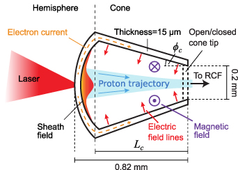
Figure 1. Schematic of the laser interaction with the hemisphere-cone target, depicting the formation of electric and magnetic fields on the inner surfaces and the resulting focused proton beam.
Download figure:
Standard image High-resolution imageThe laser was incident at 8∘ with respect to the hemisphere-cone axis, in the polarisation plane. Protons accelerated via the TNSA mechanism were measured using stacked dosimetry film (RCF), interspaced with plastic and iron foils for filtering, providing spectral and spatial characterization of the proton beam at specific energies. Each RCF layer has transverse dimensions of 10 cm × 7 cm and the stack was placed 10 cm from the position of the laser-target interaction.
Example RCF images for the three target types are shown in figure 2, showing the spatial distribution of the proton beam for the various energies indicated. These are representative of a sample of a minimum of three shots of each target type. Note that there is a transition between RCF material from ∼24 MeV to 38 MeV in order to increase the sensitivity to proton deposition at the higher energies at which the proton flux substantively decreases. The strong proton line signal at the lowest energy in all cases is likely to be produced by protons accelerated from the cylindrical target stalk. In addition to flowing along the hemisphere-cone target, fast electrons will flow along the stalk [25, 36] creating a relatively weak electric field that will ionise and accelerate protons along the normal to the curved stalk surface. A vertically orientated stalk will produce a horizontally orientated line of low energy protons, similar to that of a wire target [37, 38]. This effect can also be observed in transverse-sized limited targets [26, 39]
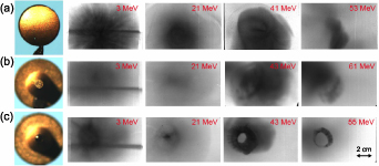
Figure 2. Example RCF images comparing the proton beam profiles at stated energies for: (a) the hemisphere target; (b) the closed-tipped hemisphere-cone target; and (c) the open-tipped hemisphere-cone target. Note that a higher dose sensitivity RCF was used for energies greater than 38 MeV.
Download figure:
Standard image High-resolution imageFor the case of the hemisphere (i.e. without cone), as shown in figure 2(a), the generated proton beam exhibits a relatively TNSA-like profile with energies reaching beyond 53 MeV. This provides a reference case to compare with when adding the cone section to the target, although it should be noted that the laser energy was ∼20% lower than for the cone target cases, which means a lower peak laser intensity. This difference will affect the maximum proton energy, but will have limited effect on the overall proton spectrum. As shown in figure 2(b), the proton beam measured with the closed-tipped hemisphere-cone target is broadly similar, with evidence of the proton beam being more diffuse, particularly at the higher energies. The biggest difference is achieved for the case of the open-tipped target, shown in figure 2(c). A narrow spatial feature is observable at 21 MeV, indicating proton beam focusing, and at higher energies, a prominent ring-like feature is also observed.
Figure 3 shows an extended energy range of RCF images for the open-tipped hemisphere-cone target shot. This clearly shows an increase in the focusing effect as the proton energy increases up to ∼24 MeV. It is also at around this energy and higher that the ring profile is observed.
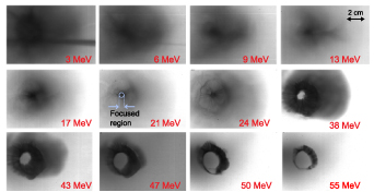
Figure 3. Extended set of RCF data showing the proton spatial distribution at stated energies for the open-tipped hemisphere-cone target. A central region of interest (with diameter equal to 0.5 cm) corresponding to the focused proton component is indicated in the measured beam profile at 21 MeV.
Download figure:
Standard image High-resolution imageThere are no significant differences in the measured spatially-integrated proton spectrum for the three target types, as shown in figure 4(a). This is expected because the laser-plasma interaction physics is the same in all three cases; the same wall thickness and material in the hemisphere part of the target and very similar laser pulse parameters produces very similar laser-to-proton energy conversion and proton beam temperature. This can be verified when observing the ratios of the integrated proton signal obtained for each target type to the hemispherical target case, seen in figure 4(b). When a region of the proton beam, of diameter 0.5 cm sampled at the averaged centre of each beam, is compared in figure 4(c), it becomes apparent that the open cone case exhibits a higher proton signal within the energy range 9–24 MeV in comparison to both the closed cone and hemisphere only cases. This is almost a factor of 5 increase for the open cone case, as seen in the corresponding ratios in figure 4(d). This demonstrates that the addition of the cone structure acts to change the local proton signal in specific energy ranges without impacting on the overall proton numbers. This implies a focusing of the protons, enhancing the flux in the case of an open-tip cone but with no corresponding focusing or enhancement for the closed cone case at these energies.
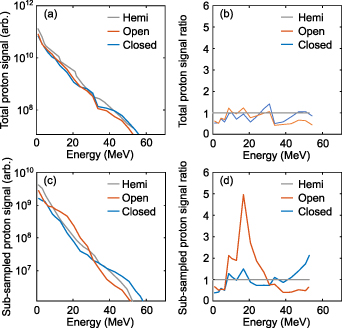
Figure 4. (a) Measured proton energy spectrum spatially integrated over the full beam (full RCF) for a hemisphere target (gray), an open-tipped hemisphere-cone target (green) and a closed-tipped hemisphere-cone target (blue). (b) The ratio of total integrated proton signal to the total integrated hemisphere target proton signal in the corresponding colours. (c), (d) Same, for a sub-sample of the protons within a diameter of 0.5 cm centred on the averaged central position of the proton beam in each case. This region is indicated on figure 3.
Download figure:
Standard image High-resolution image3. Simulations of proton beam propagation
To explore the underlying physics of the effects of the cone structure on the beam of propagating protons, scaled 2D simulations were undertaken using the fully relativistic PIC code EPOCH [40]. These simulations are not designed to replicate the precise parameters of the experiment, but are simplified within the limits of computational resource available, to investigate the role of the cone. The hemisphere part of the target which provides the source of the protons is reduced to a planar foil to enable the effects of the cone to be investigated without the presence of the potential additional focusing effects of the hemispherical targets. To achieve the mesh resolution required to resolve wave behaviour in dense plasma, the size of the cone and the laser pulse intensity, duration and spot size are all scaled down compared to the experiment. The cone dimensions are scaled such that the transit time of the highest energy protons to the cone tip as a function of laser pulse duration is comparable to the experiment.
The simulation grid consisted of 16 000 × 5760 cells, corresponding to a domain size of 160 µm × 100 µm. The injected laser pulse was linearly polarised in the Y direction, propagating along the X-axis, with a Gaussian temporal profile of 300 fs (FWHM), a focused Gaussian focal spot distribution of 3 µm (FWHM) and a peak intensity of  Wcm−2. Three target profiles were used. The first was a 5 µm planar target slab of heavy ions with charge state, Z = 11, and mass of 30 proton masses, with a 50 nm proton source layer at the rear (this was defined such that there was sufficient mesh cells across the contamination layer). The second profile was that of an closed-tip hollow conical target with 5 µm-thick heavy ion walls and opening angle φc
= 20∘. The diameter of the cone base (wall irradiated by the laser pulse) and longitudinal length of the cone Lc
were 80 µm and 50 µm, respectively. A 50 nm proton source layer was included at the rear of the base (i.e. rear side of the irradiated surface). The third profile was the same as the second, except that the end of the cone was open. In all cases, an exponentially decreasing density with scale length equal to 1 µm is included at the front surface of the target to approximate laser contrast effects and to prevent perfect reflection. The exact expansion profile due to the laser intensity-contrast during the experiment was not measured, but as the initial simulated scale-length is fixed for each target type, the impact of the plasma scale length on the effect of the cone can be neglected. A corresponding neutralising electron population with a peak density of 630
Wcm−2. Three target profiles were used. The first was a 5 µm planar target slab of heavy ions with charge state, Z = 11, and mass of 30 proton masses, with a 50 nm proton source layer at the rear (this was defined such that there was sufficient mesh cells across the contamination layer). The second profile was that of an closed-tip hollow conical target with 5 µm-thick heavy ion walls and opening angle φc
= 20∘. The diameter of the cone base (wall irradiated by the laser pulse) and longitudinal length of the cone Lc
were 80 µm and 50 µm, respectively. A 50 nm proton source layer was included at the rear of the base (i.e. rear side of the irradiated surface). The third profile was the same as the second, except that the end of the cone was open. In all cases, an exponentially decreasing density with scale length equal to 1 µm is included at the front surface of the target to approximate laser contrast effects and to prevent perfect reflection. The exact expansion profile due to the laser intensity-contrast during the experiment was not measured, but as the initial simulated scale-length is fixed for each target type, the impact of the plasma scale length on the effect of the cone can be neglected. A corresponding neutralising electron population with a peak density of 630 for the heavy ions and 50
  for the protons was initialised with an initial electron temperature of 10 keV. Figures 5(a)–(c) shows the three target profiles modelled, with proton trajectories tracked. For the results that follow, t = 0 is defined as the time at which the peak of the pulse reaches the front surface of the target. Initial test simulations included a proton layer along the entire cone surface, but only a very small population reached energies up to 12 MeV and the rest only acted to add noise to the lower energy results. As such, and to avoid the additional computational resource required, the proton layer was not extended along the entire cone surface.
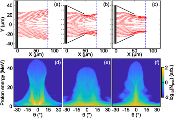
Figure 5. (a)–(c) PIC simulation results showing proton trajectories (red) from  0 ps to
  1.2 ps, shown together with the target profile (black), for (a) a planar target, (b) a planar target with closed cone, and (c) a planar target with open cone (target details are given in the main text). The protons sampled are initially uniformly positioned along the Y axis at the rear of the planar foil region and have a final energy of 15 MeV. (d)–(f) The corresponding proton number as a function of energy and proton angle with respect to the laser axis (Y = 0) at
  1.2 ps for all protons. This time corresponds to when most protons
  5 MeV have moved beyond X = 60 µm. The blue dashed lines in (a)–(c) indicate the approximate position in X of most protons with a final energy of 15 MeV protons in (d)–(f).
Download figure:
Standard image High-resolution imageIndividual protons are tracked throughout the simulations to investigate the effects of the cone structures on the divergence properties of the proton beam. A uniformly distributed transverse sample of protons at the source (the initial proton layer) with a final energy of 15 MeV are shown for the three target types in figures 5(a)–(c). For the case of the planar target (figure 5(a)), the protons exhibit a divergent spread that is typical of TNSA, with the highest energy protons directed along the target-normal direction (which is also the laser axis). For the closed cone (figure 5(b)), the initial expansion is similar to that of the planar target, but as the protons at large radii move close to the cone walls they are deflected back towards the axis. Protons passing through the cone end wall are subject to the electrostatic and magnetic fields established there, and the final beam has a similar overall divergence as the beam produced by the planar foil alone, but with degraded laminarity. For the case of the open cone (figure 5(c)), the deflection of protons towards the central axis (i.e. focusing effect) also occurs near the cone wall, but the absence of the end wall enables the protons to propagate out of the cone without additional perturbation. The net result is a proton beam that is more collimated, particularly at low to medium energies.
The angular distribution, determined algorithmically for every proton angle, θ, using the function atan2 , where PX
and PY
are the proton longitudinal and transverse momentum respectively, as a function of energy at the end of the simulation (t = 1.2 ps) is shown in figures 5(d)–(f) for the three target cases. This is sampled at t = 1.2 ps when most protons above 5 MeV have passed X = 60 µm (i.e. after the cone tip). At this stage, the space-charge spreading of the protons is reduced by the presence of a co-moving population of electrons and they travel ballistically. As such, we can consider this analogous to beam divergence for the different proton energies. The dashed blue lines in figures 5(a)–(c) indicate the approximate position of most of the 15 MeV protons in space at this time. The planar foil case (figure 5(d)) exhibits a typical TNSA-proton beam divergence, with a wide ring-like distribution at the lower energies driven by expansion of the heavy ions [41]. This is exaggerated due to the reduced scale simulation parameters. When a closed cone is introduced (figure 5(e)), the maximum proton energy is reduced and the lower energy component becomes more diffuse due to the deflection induced by the cone end wall. For the case of the open cone tip (figure 5(f)), the relatively low energy component, from 5–30 MeV, of the beam is collimated and a smaller ring structure, in comparison to the planar target, appears at the higher energies. These features are qualitatively similar to those measured experimentally when introducing the open tip cone.
, where PX
and PY
are the proton longitudinal and transverse momentum respectively, as a function of energy at the end of the simulation (t = 1.2 ps) is shown in figures 5(d)–(f) for the three target cases. This is sampled at t = 1.2 ps when most protons above 5 MeV have passed X = 60 µm (i.e. after the cone tip). At this stage, the space-charge spreading of the protons is reduced by the presence of a co-moving population of electrons and they travel ballistically. As such, we can consider this analogous to beam divergence for the different proton energies. The dashed blue lines in figures 5(a)–(c) indicate the approximate position of most of the 15 MeV protons in space at this time. The planar foil case (figure 5(d)) exhibits a typical TNSA-proton beam divergence, with a wide ring-like distribution at the lower energies driven by expansion of the heavy ions [41]. This is exaggerated due to the reduced scale simulation parameters. When a closed cone is introduced (figure 5(e)), the maximum proton energy is reduced and the lower energy component becomes more diffuse due to the deflection induced by the cone end wall. For the case of the open cone tip (figure 5(f)), the relatively low energy component, from 5–30 MeV, of the beam is collimated and a smaller ring structure, in comparison to the planar target, appears at the higher energies. These features are qualitatively similar to those measured experimentally when introducing the open tip cone.
Another feature similar to the experiment results is that the spatially-integrated spectrum of the proton beam (at the end of the simulation, t = 1.2 ps) is very similar for all three target cases, as shown in figure 6(a). There is a slight reduction in the proton numbers for both the open- and closed-tip cones above 2 MeV, with a small reduction in maximum proton energy as well. This can also be seen when comparing the ratios of the spectra of each target type with the reference planar case in figure 6(b). When comparing the collimated proton distributions, defined within the angular range  (i.e. close to the central propagation axis), shown in figure 6(c), the open cone case is observed to produce a substantially higher proton flux between 5 and 30 MeV in comparison to the planar case. The ratios of each of the collimated spectra to the collimated planar target spectra show that this increases up to a factor of 5 in figure 6(d). This corresponds to greater collimation of the proton beam in this energy range. By contrast, for the closed cone case, the number of collimated protons is significantly reduced over the same energy range. Again, this is qualitatively similar to the behaviour observed experimentally for the energy spectra associated with the localised proton feature in the open cone case.
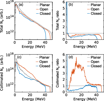
Figure 6. PIC simulation results: (a) full beam energy spectra for a planar target (gray), a planar target with closed cone (blue), and a planar target with open cone (red). (b) The ratio of each spectra to the planar target case in the corresponding colours. (c)–(d) Same, for collimated protons defined with an angular range of  . This is sampled for all protons at t = 1.2 ps, when most
  5 MeV protons have moved beyond X = 60 µm.
Download figure:
Standard image High-resolution imageTo elucidate the effects of the cone walls and tip on the proton beam propagation, the spatial distribution of the longitudinal (EX ) and transverse (EY ) electric fields and azimuthal (BZ ) magnetic fields are shown in figures 7(a)–(c), respectively for the closed case, and in (d)–(f) for the open tip case. The distributions are shown at t = 1 ps, at which time the fast electrons have propagated from the laser–plasma interaction region along the cone walls to the tip, establishing the full complement of field profiles. For both the open and closed tip cases, strong EY fields are produced at the inner surface of the cone walls along with corresponding strong BZ fields. The Lorentz force component associated with the BZ field will act to diverge the protons away from the central axis. However, the stronger force component from the EY field will act to deflect the protons towards the central axis, resulting in an overall collimating effect on the proton beam. For the case of the closed cone, the BZ field extends to the end-wall of the cone (figure 7(c)), whereas the EY is truncated earlier due to the electron current dynamics in the end wall (figure 7(b)). By contrast, the EY field is maximised at the cone tip and extends beyond it for the open-tipped case (figure 7(e)). Effectively the fields are stronger at the tip because of the lack of material to form a return current, leading to charge build-up [42]. These fields may be produced by a combination of two effects. The first is due to expansion of the plasma from the cone walls induced by heating due to the arrival of the fast electrons from the laser interaction region, predominantly resulting in the electric field normal to the cone walls. The second is the current flow along the cone walls towards the cone base, arising from the positive charge build-up due to expulsion of electrons. This would lead to the formation of the azimuthal magnetic field around the cone walls.
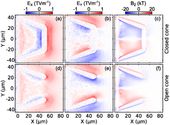
Figure 7. PIC simulation results: (a) longitudinal electric field EX , (b) transverse electric field EY , and (c) azimuthal magnetic field BZ , for the closed cone case at t = 1 ps. (d)–(f) Corresponding results for the open cone case.
Download figure:
Standard image High-resolution imageFor both cases, a positive EX field is observed in the proton source region at the base wall of the cone. This is a remnant of the TNSA field. For the case of the closed cone, there is a very strong negative EX field at the inner surface of the cone tip or end-wall (figure 7(a)). This is formed due to the fast electron population arriving at the end-wall, prior to the protons. At the outer side of the cone end-wall, there is another positive EX sheath field formed due to the same fast electron population. These fields, which have a decelerating and accelerating influence, respectively, as protons pass through the end-wall of the cone are not present along the central axis of the open-cone case (figure 7(d)).
The fields produced by the fast electrons propagating within the cone walls are transient in nature, and their temporal evolution, sampled at X = 40 µm, is shown in figure 8. The transverse expansion of the plasma from the cone walls can be observed at the same rate in both cone types. A strong negative (decelerating) EX field grows over the course of the simulation for the closed cone case, as seen in figure 8(a). Note, as this is sampled at a fixed line in space (X = 40 µm), the plasma will be expanding into the sample region resulting in an increase to the field strength. This field is not observed in the case of the open cone in figure 8(d).
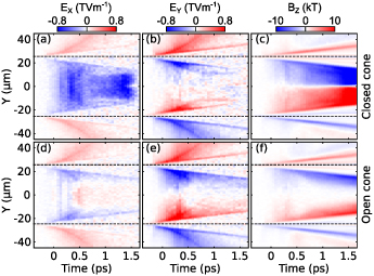
Figure 8. PIC simulation results: (a) longitudinal electric field, (b) transverse electric field, and (c) azimuthal magnetic field, as a function of time at X = 40 µm, for the closed cone case. (d)–(f) Corresponding results for the open cone case. The dashed black lines indicate the initial Y position of the centres of the cone walls at this X position.
Download figure:
Standard image High-resolution imageThe EY
fields are of comparable strength up to  ps for the closed and open cases, seen in figures 8(b) and (e) respectively, but reduces significantly in the closed case after this time due to the current dynamics, inhibiting focusing of the protons. The BZ
field grows in strength throughout the simulation for both cases, seen in figures 8(c) and (f) for the closed and open cases respectively, but is stronger near the central axis for the closed case, in part due to plasma expansion from the cone tip wall. This will act to diverge the protons in the closed cone case.
ps for the closed and open cases, seen in figures 8(b) and (e) respectively, but reduces significantly in the closed case after this time due to the current dynamics, inhibiting focusing of the protons. The BZ
field grows in strength throughout the simulation for both cases, seen in figures 8(c) and (f) for the closed and open cases respectively, but is stronger near the central axis for the closed case, in part due to plasma expansion from the cone tip wall. This will act to diverge the protons in the closed cone case.
To investigate the effect these temporally and spatially varying fields have on proton propagation within the cone, all protons that have a final energy of (15±1) MeV are considered from each simulation. This energy is chosen as this exhibits the most proton focusing as seen in figure 5(f). These protons are tracked through the simulations and the distribution of the EX , EY , and BZ fields experienced by the particles are shown as a function of time in figures 9(a)–(c), respectively, for the planar target case. The angular distribution of the (15±1) MeV and (5±1) MeV components of the proton beam are shown as a function of time in figures 9(d) and (e), respectively. The corresponding plots for the closed and open cone cases are shown in figures 9(f)–(j) and (k)–(o), respectively. For all cases, an averaged sample of the particles with an initial position of Y = (5±1) µm is shown as the red line for each plot to aide in demonstrating the dynamics of off-axis protons.
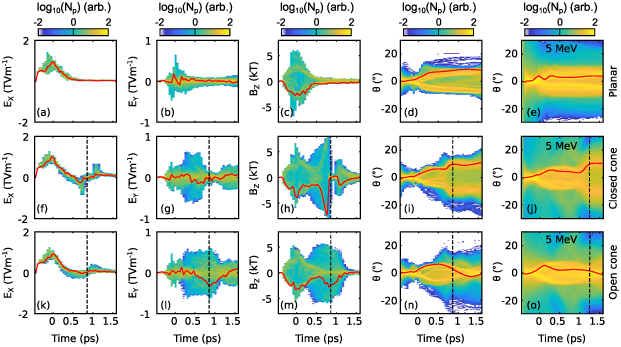
Figure 9. PIC simulation results: distribution of the (a) longitudinal electric field, (b) transverse electric field, and (c) azimuthal magnetic field experienced by protons with a final energy of (15±1) MeV, as a function of time, for the planar target case. Angular distribution of the (d) (15±1) MeV and (e) (5±1) MeV components of the proton beam as a function of time. (f)–(j) Corresponding plots for the closed cone case; (k)–(o) corresponding plots for the open cone case. The red line corresponds to an averaged sample of the same protons with an initial position of Y = (5±1) µm. The dashed black line indicates when most of the protons with specified energy reach the cone tip.
Download figure:
Standard image High-resolution imageLongitudinal electric fields—For all three cases, the protons are accelerated by the strong TNSA field at the rear surface of the laser-irradiated foil. This field maximises at about the peak of the laser pulse interaction and decreases afterwards as the proton layer expands away from the rear surface. In the case of the planar target without cone, no further EX field is experienced. By contrast, for the closed cone, the protons approaching the cone end-wall experience the negative field observed in figures 7(a) and 8(a). For the open cone case, a negative EX field is experienced due to the cone walls, but this is significantly smaller than experienced for the closed cone. As the sampled protons pass through the end of the cone, they again experience a positive EX field at the rear of the closed cone wall and the edge of the walls for the open case. This effect is stronger in the closed cone case due to the larger transverse extent of the end cap.
Transverse electric fields—For the planar target without cone, the protons do not experience a significant EY
field other than that induced by space-charge build up due to deformation of the rear surface [41, 43]. This behaviour is similar for the closed and open cone cases up until the point in time ( ps) at which the protons start to approach the cone walls. At this point, they start to experience a strong EY
field directed radially inwards, which continues until the protons reach the end wall or pass beyond the cone tip in the case of the closed and open cases, respectively. These protons experience the EY
field for longer in the open cone case, and are directed towards the central axis, as observed in the angular distribution at t = 0.5 ps in figure 9(n). As they do so, there is a build up of positive charge and they start to experience a positive EY
field due to the space-charge effect of the proton beam. This prevents the protons from crossing and results in a collimating effect at this particular energy. At higher energies, the proton numbers are smaller, reducing space-charge effects that would otherwise lead to strong Coulomb repulsion, and thus these protons pass through focus and produce an annular distribution.
ps) at which the protons start to approach the cone walls. At this point, they start to experience a strong EY
field directed radially inwards, which continues until the protons reach the end wall or pass beyond the cone tip in the case of the closed and open cases, respectively. These protons experience the EY
field for longer in the open cone case, and are directed towards the central axis, as observed in the angular distribution at t = 0.5 ps in figure 9(n). As they do so, there is a build up of positive charge and they start to experience a positive EY
field due to the space-charge effect of the proton beam. This prevents the protons from crossing and results in a collimating effect at this particular energy. At higher energies, the proton numbers are smaller, reducing space-charge effects that would otherwise lead to strong Coulomb repulsion, and thus these protons pass through focus and produce an annular distribution.
Azimuthal magnetic field—Strong BZ fields induced at the proton source region at the rear side of the planar foil act to initially diverge the proton beam [44]. This decays in the case of the planar target as the protons expand. For the cone cases, as the protons approach the cone walls they begin to experience the BZ field present at the inner surface of the walls, which acts to diverge the protons. The divergence induced by this field is overcome by the focusing effect of the EY field in the case of the open cone. For the closed cone, the protons experience a very strong magnetic field at the inner surface of the end cap which further acts to diverge the protons, as observed in the angular distribution at t = 0.7 ps in figure 9(i).
As some potential applications of laser-accelerated protons, such as PFI, can require focused beams of lower energy protons [13], the temporal behaviour of the angular distribution of (5±1) MeV protons is shown for the planar target without cone, the closed cone and the open cone in figures 9(e), (j) and (o), respectively. This demonstrates that the same effects are experienced by these lower energy protons, albeit delayed in time due to the slower transit time of the protons from the source to the end of the cone.
4. Energy selective cone-focusing
Given that the fields generated along the walls of an open-tipped cone can induce a focusing effect on protons within a particular proton energy range, we next consider how the energy range can be varied. To achieve this, additional 2D PIC simulations were conducted to test the effects of varying both the cone angle (φc
) and the cone length (Lc
) for the open cone case. Previously, these values were fixed at  and Lc
= 50 µm (for both the open and closed cone simulations). In the first additional set of simulations, φc
was varied in the range 4∘–28∘ with fixed Lc
= 50 µm, and in the second set, Lc
was varied from 30–70 µm for fixed
and Lc
= 50 µm (for both the open and closed cone simulations). In the first additional set of simulations, φc
was varied in the range 4∘–28∘ with fixed Lc
= 50 µm, and in the second set, Lc
was varied from 30–70 µm for fixed  . All other laser and target parameters were kept the same as the previous set of simulations.
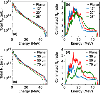
As shown in figure 10, it is found that varying φc
with a fixed Lc
does not significantly impact upon the focusing behaviour. As the φc
is increased there is a reduction in the total numbers of accelerated protons above 5 MeV up to ∼50% at  as seen in figure 10(a). This is due to the larger opening angle resulting in a smaller angle between the rear surface of the foil and the walls, which acts to direct the electric field more in the opposite longitudinal direction to the protons, resulting in deceleration. When considering the degree of collimation, i.e. the change in flux within
  , a slight enhancement is observed at higher energies with increasing φc
, however there is reduction in lower energy proton numbers in comparison to the lower φc
values, again due to the smaller angle between the rear surface and the walls predominately affecting the protons far from the laser axis which correspond to the lowest energy protons. Overall, there is an improvement in beam collimation over the planar target in all φc
cases considered. This can be observed from the ratio of the number of collimated protons from each open cone case to the collimated protons from the planar target, shown in figure 10(b).
, a slight enhancement is observed at higher energies with increasing φc
, however there is reduction in lower energy proton numbers in comparison to the lower φc
values, again due to the smaller angle between the rear surface and the walls predominately affecting the protons far from the laser axis which correspond to the lowest energy protons. Overall, there is an improvement in beam collimation over the planar target in all φc
cases considered. This can be observed from the ratio of the number of collimated protons from each open cone case to the collimated protons from the planar target, shown in figure 10(b).
Figure 10. PIC simulation results: (a) proton energy spectra for three open-tipped cone opening angles,  (blue), 20∘ (red), 28∘ (green), alongside results for a planar target (black dashed). (b) Ratio between the cone cases and the reference planar target case for collimated protons defined as within
  . (c) Proton energy spectra for three open-tipped cone lengths,
  µm (blue), 50 µm (red) and 70 µm (green) (all with
  ), together with results for a planar target (black dashed). (d) Ratio between the cone cases and the reference planar target case for protons collimated protons defined as within
  .
.
Download figure:
Standard image High-resolution image
With increasing Lc , for fixed φc , the total proton number with energy above 5 MeV decreases, as figure 10(c) demonstrates. This is due to the protons experiencing a longer interaction time, due to increased length, with the longitudinal fields on the interior surfaces acting to decelerate the protons. As shown in figure 10(d), smaller Lc results in reduced collimation above 5 MeV. Importantly, with increasing Lc the spectral region for which collimation occurs shifts to higher energies, resulting in higher flux in the 30–45 MeV range. Thus, the cone length is observed to have the most impact on the proton energy that is collimated by the transient fields. In this way, the geometry of the open cone can be tailored to improve the proton flux at specific energy ranges for which proton flux enhancement is required for application.
5. Summary
The use of a hollow cone attached to a laser-irradiated target has been investigated to explore its role in focusing laser-accelerated protons. Specifically, the role of the cone tip is addressed by comparing open- and closed-tipped configurations. Experimentally it is found that an open-tipped cone, attached to the rear of a hemispherical target, produces focusing of accelerated protons at mid-range energies and a ring-like beam structure at higher energies. These beam distributions are distinctly different from those measured with a hemisphere target without cone and with a closed-tipped hemisphere-cone. Scaled PIC simulations to explore the effects of the cone structures reveal that transient electric fields produced by fast electrons travelling from the laser-plasma interaction region along the cone surface deflect protons travelling within the cone radially inwards towards the central axis. The proton energy range over which this focusing occurs depends on which protons are passing near to the tip when the transient fields are strongest. A strong azimuthal magnetic field is also produced, which can act to increase beam divergence. For the case of an open-tipped cone, the influence of this field is overcome by the focusing effect of the transverse electric field. By contrast, in the case of the closed cone, for which the azimuthal magnetic field is stronger and the transverse electric field is weaker compared to the open-tipped cone, enhanced beam divergence occurs over a specific proton energy range, again defined by the time of flight of the protons through the cone.
In the simulations, the presence of the hemisphere front surface has been removed due to the scaled nature of the simulations and to isolate the effects of the cone walls. It should be noted that the protons measured experimentally may have additional focusing behaviour included due to the presence of the hemisphere [23]. As this source of focusing would also occur for the hemisphere-only target, we conclude that the much stronger selective energy focusing observed is induced by the cone walls, as demonstrated numerically.
Likewise, the simulations have assumed a fixed initial density scale length at the front surface of the target. Additional simulations were conducted for a reduced scale-length, which results in the same overall focusing behaviour, but with slightly different maximum proton energies and energies focused by the open cone. The scale length will vary depending on the laser intensity contrast prior to the peak of the pulse, and as such, the energy distribution of the protons accelerated from the inner cone base surface can be affected. This needs to be considered when tailoring the energy at which focusing occurs.
Further simulations, to explore the influence of the overall geometry of the open-tipped cone, reveal that the angle of the cone walls do not have a significant impact on the focusing behaviour, but extending the length of the cone shifts the focusing effect to higher energy protons. This in effect changes the transit time for the fast electrons from the laser–plasma interaction region to the cone tip, and thus the transient fields act on a different part of the proton energy spectrum. This demonstrates that through suitable choice of cone geometry, the proton beam focusing can be tailored to energies required for a specific application. This could influence the design of cone-guided targets for applications in warm dense matter physics and PFI, for which a high flux of protons within a specific energy range is required for heating.
Acknowledgments
This work was supported by STFC and AWE through the Orion laser Academic Access Programme and via Grant Number ST/V001612/1, by EPSRC (Grant Numbers EP/R006202/1 and EP/V049232/1) and by Laserlab-Europe (Grant Agreement No. 871124, European Union's Horizon 2020 research and innovation programme). The ARCHER2 high performance computer was used, with access provided via the Plasma Physics HEC Consortia (EP/R029148/1). EPOCH was developed under EPSRC Grant EP/G054940/1. A H acknowledges studentship co-funding from AWE and M W acknowledges support from General Atomics's internal research and development program. The authors would like to acknowledge the entire Orion team at AWE for their help and support during the experiment.
Prof. David Neely sadly passed away before this work was published.
Data availability statement
The data that support the findings of this study will be openly available following an embargo at the following URL/DOI: https://doi.org/10.15129/9cdd2ccc-6dfa-4bb4-9678-4c6f467afdd5. Data will be available from 31 October 2023.