

Abstract
Objective. Carbon is an ion species of significant radiobiological interest, particularly in view of its use in cancer radiotherapy, where its large Relative Biological Efficiency is often exploited to overcome radio resistance. A growing interest in highly pulsed carbon delivery has arisen in the context of the development of the FLASH radiotherapy approach, with recent studies carried out at dose rates of 40 Gy s−1. Laser acceleration methods, producing ultrashort ion bursts, can now enable the delivery of Gy-level doses of carbon ions at ultra-high dose rates (UHDRs), exceeding 109 Gy s−1. While studies at such extreme dose rate have been carried out so far using low LET particles such as electrons and protons, the radiobiology of high-LET, UHDR ions has not yet been explored. Here, we report the first application of laser-accelerated carbon ions generated by focussing 1020 W cm−2 intense lasers on 10–25 nm carbon targets, to irradiate radioresistant patient-derived Glioblastoma stem like cells (GSCs). Approach. We exposed GSCs to 1 Gy of 9.5 ± 0.5 MeV/n carbon ions delivered in a single ultra-short (∼400-picosecond) pulse, at a dose rate of 2 × 10⁹ Gy s−1, generated using the ASTRA GEMINI laser of the Central Laser Facility at the Rutherford Appleton Laboratory, Didcot, Oxfordshire, UK. We quantified carbon ion-induced DNA double strand break (DSB) damage using the 53BP1 foci formation assay and used 225 kVp x-rays as a reference radiation. Main Results. Laser-accelerated carbon ions induced complex DNA DSB damage, as seen through persistent 53BP1 foci (11.5 ± 0.4 foci/cell/Gy) at 24 h and significantly larger foci (1.69 ± 0.07 μm2) than x-rays induced ones (0.63 ± 0.02 μm2). The relative foci induction value for laser-driven carbon ions relative to conventional x-rays was 3.2 ± 0.3 at 24 h post-irradiation also confirming the complex nature of the induced damage. Significance. Our study demonstrates the feasibility of radiobiology investigations at unprecedented dose rates using laser-accelerated high-LET carbon ions in clinically relevant models.
Export citation and abstract BibTeX RIS

Original content from this work may be used under the terms of the Creative Commons Attribution 4.0 licence. Any further distribution of this work must maintain attribution to the author(s) and the title of the work, journal citation and DOI.
1. Introduction
The radiobiology of ion beams has been the subject of intense investigation in view of its relevance to advanced forms of cancer therapy, where ion beams allow precise dose deposition within the tumour volume by exploiting the Bragg peak profile (DeLaney 2018, Durante and Flanz 2019, Kim and Wu 2021). This precise dose delivery offers significant normal tissue sparing thus widening the therapeutic window, and resulting in effective treatment of tumours in the close vicinity of critical organs (Kim and Wu 2021, Park et al 2021). While the majority of the ion treatment centres currently in operation employ protons, there is significant interest in the use of higher-Z species. For example, the high LET of carbon ions leads to more complex cellular DNA damage resulting in higher relative biological effectiveness (RBE) than protons and other low LET radiation. This is exploited for the treatment of radioresistant (Arians et al 2019, Chiblak et al 2019) and hypoxic tumours (Klein et al 2017) by employing carbon ions from a synchrotron, which are typically delivered at a dose-rate of a few Gy/min.
There is currently an increasing interest in new radiotherapy approaches employing significantly higher dose rates. This is due to the recent demonstration of the normal tissue sparing effects of radiation delivered at high-dose rate, which have highlighted the so-called FLASH approach as the next step towards an advanced and more effective form of cancer radiotherapy (Bourhis et al 2019, Montay-Gruel et al 2019, Vozenin et al 2019). Most of these studies have been carried out with low LET radiation (primarily electrons) and dose rates ranging from 40 Gy s−1 to 1000 Gy s−1. Recently the first Carbon FLASH in-vitro irradiation set up has been demonstrated, operating at 40 Gy s−1 dose rates (Tinganelli et al 2022).
Laser-driven ion acceleration techniques provide bursts of radiation which are intrinsically ultrashort (Fuchs et al 2006, Dromey et al 2016) at the source (with duration of order picosecond and below), and offer the opportunity to extend these investigations to much-higher, largely unexplored dose rate ranges. Several experiments have reported the delivery of Gy-level proton doses in single pulses of nanosecond duration, reaching dose rates in the order of 109 Gy s−1 (Bin et al 2012, Doria et al 2012, Hanton et al 2019, Brack et al 2020, Chaudhary et al 2021, Yang et al 2021). The main aim of these activities is to explore how the ultra-short delivery time scales impacts the radiobiological outcome, which is essentially unknown under such extreme conditions. Extending studies to these extreme regimes has the potential to provide important novel information on the fundamentals of radiation-cell interactions.
So far, laser-driven radiobiology experiments have employed protons accelerated through the Target Normal Sheath Acceleration mechanism (Snavely et al 2000). This is the most established laser-based approach to proton acceleration, which acts on surface ion layers, typically hydrogen-rich contaminants. Emerging acceleration mechanisms which are effective on the bulk of the target offer the opportunity for efficient acceleration of higher-Z ions, including carbon (Henig et al 2009, Bin et al 2015, Scullion et al 2017). Of particular interest is, in this context, the use of ultrathin foils, with a thickness in the order of 10 nm. Recent experiments have shown that, under appropriate conditions, it is possible to accelerate, from such foils, carbon ions to energies of several tens of MeV per nucleon (Scullion et al 2017), as well as producing proton-free, large flux carbon beams (McIlvenny et al 2021). Laser-driven carbon beams also share the short duration properties discussed above, and provide unique opportunities for radiobiological investigations at high LET and ultra-high dose rate (UHDR). Here, we report on the outcome of the first proof-of-principle experiment aimed at cellular irradiations employing laser-driven carbon ions at an UHDR of 2.5 × 10⁹ Gy s−1. The carbon ions were accelerated from an ultrathin carbon foil and were delivered to the cells by employing a simple transport system based on a strong (∼1 T) magnetic dipole. The cells irradiated were patient-derived radioresistant Glioblastoma stem cells (GSCs). Our results confirm the expected enhanced effectiveness of laser-driven carbon ions relative to 225 kVp x-rays for the induction of DNA DSB damage in radioresistant cancer stem cells, and demonstrate the feasibility of performing radiobiology experiments with laser-driven carbon ions at extreme dose rates.
2. Materials and methods
2.1. Ion acceleration and transport
Carbon ions were accelerated using the Astra GEMINI laser system of the Central Laser Facility at the Rutherford Appleton Laboratory, UK, that delivered ∼12 J, 40 fs single pulses onto ultrathin carbon foil targets, at intensities ∼6 × 10²⁰ W cm−2, by an f/2 parabola. We used a double plasma mirror system for pulse contrast enhancement. To generate the carbon ion beam, we used 15 nm thick targets, which were irradiated by linearly polarized pulses at normal incidence. Under these conditions, the acceleration of ions from the target bulk takes place under the influence of multiple acceleration mechanisms. The carbon ions initially undergo radiation pressure acceleration in the Light Sail mode (Henig et al 2009, Macchi 2010) until the target becomes transparent to the relativistically intense laser pulse - during this second phase, efficient coupling of the laser pulse into electrons, as it propagates through the dense target plasma, leads to an enhancement of the accelerating fields which boosts the ion energy(Henig et al 2009, Higginson et al 2018) We note that the highest carbon energies can generally be obtained by using circularly polarized laser pulses, which reduce target heating and delay the onset of transparency(Scullion et al 2017, McIlvenny et al 2021) However, linear polarization was chosen in our experiment as it allowed the production of a more stable and uniform beam at the chosen ion energies of 10 MeV n−1.
The proton and carbon-ion energy spectra were measured by using a Thomson Parabola Spectrometer (TPS) placed along the target-normal direction, coupled with BAS-TR Image Plates (IP). Figure 1(A) shows the energy spectra measured in a single shot for protons and carbon ions (C6+). Under the conditions of the experiment, we typically obtain comparable cutoff energies/nucleon for carbon ions and protons (Scullion et al 2017) (with carbon ions slightly more energetic than protons in the data shown in figure 1(A)).
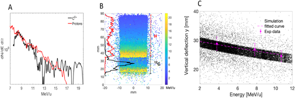
Figure 1. (A) Proton and carbon (C6+) energy distributions measured with the Thomson Parabola coupled with an Image Plate along the target-normal direction employing a 15 nm carbon target in linear polarization. (B) Geant4 simulation of the spatial particle distribution at the cell plane for both protons and carbon ions deflected by the magnetic dipole. The color scale shows the energy per nucleon (MeV u−1) while the left vertical axis shows the fluence distribution of protons (red line) and carbon ions (black line) calculated with the simulation. (C) Comparison between the simulated spatial energy dispersion (black points) at the cell plane and those obtained experimentally (red points) by using radiochromic films (RCF) covered by 3 different aluminium absorbers.
Download figure:
Standard image High-resolution imageGiven the multi-species nature of the beam, and the comparable energies/nucleon of the two main species, a challenge of the experiment was designing and implementing an experimental setup that allows irradiating a cell sample with a pure carbon beam, minimizing the proton contribution to the final delivered dose at the cell plane. This was achieved by placing a 0.9 T dipole magnet at about 50 mm from the target to select in energy and spatially disperse the ion beam accelerated along the target normal direction (figure 2 part (C)) (see also (Milluzzo et al 2020)). A 500-μm width slit was used to reduce the particle divergence captured by the magnet as well as the energy spread at the cell position. The cell holder was then placed in air at about 1 cm from a 50 μm Kapton beam exit window and at total distance of about 300 mm from the target. Such distance was chosen to ensure a sufficient spatial dispersion of protons and carbon ions at the cell position as well as to spatially separate the proton and carbon beams, while ensuring a sufficient ion flux reached the cells. A Geant4- simulation reproducing the experimental setup and the condition was performed to predict the energy-spatial dispersion of protons and carbon ions. Figure 1(B) shows the spatial distribution of protons and carbon ions after the magnetic dispersion at the cell position as calculated from the Geant4 simulations. The particle energy per nucleon is also shown in the color scale bar together with the particle fluence distribution (protons and carbon ions in red and black respectively) in the vertical direction. As seen in the figure, protons and carbon ions are spatially separated at the cell location and carbon ions with an energy per nucleon on the cells around 10 MeV u−1 can be selected for the irradiation of cells without any contribution from protons. The short drift distance after the magnet also allows maintaining a sufficient high particle flux to reach Gy-level doses at the cell plane. The Geant4 model output of the experimental setup was validated by comparing the experimental spatial-energy distribution of carbon ions at the cell plane with the simulation predictions as shown in figure 1(C). The measurement has been performed by using RCF covered by different thicknesses of aluminum absorbers able to stop different carbon ion energies. By recording the signal cut-off on the RCF corresponding to the energy cut off caused by the different aluminum absorbers, it was possible to establish a correlation between the carbon ion energies and their position on the RCF. Figure 1(C). shows the comparison between the simulated energy dispersion (black point) and 3 experimental points obtained using 117, 177 and 229 um thick aluminum absorbers corresponding to an energy cut-off of 6.6, 8.6 and 10 MeV u−1 respectively.

Figure 2. Scheme for cellular irradiations. (A) Stainless steel culture dish mounted with 3 μm thin Mylar on which the E2 cells were grown. An additional Mylar window mounted on top of the dish prevented medium spillage during irradiation. (B) A RCF mask or holder was placed under the Mylar on which cells were grown. (C) Carbon ions were accelerated by focussing the high intensity laser on 15 nm carbon targets, and then selected spatially and in energy using respectively a pinhole aperture and a 1 T dipole magnet (D) Cell irradiation chamber assembly with the cell-dish mounted inside along with the RCF mask mounted under the Mylar on which cells were attached.
Download figure:
Standard image High-resolution image2.2. Cell culture and irradiation
In this study, we used patient-derived radioresistant glioblastoma stem like cells (E2 cells) that expressed the most common stem cells biomarkers such as Nestin and Sox-2 (Gomez-Roman et al 2020). The cells were cultured in Advanced DMEM-F12 medium supplemented with B27, N2, L-Glutamine, heparin, epidermal growth factor and basal fibroblast growth factor (Thermo Fischer Scientific, Loughborough, UK). Cells were grown as monolayers on top of 3 μm thick Mylar film mounted in the custom-made stainless-steel dishes (figure 2(A)). Before seeding cells, the dishes were thoroughly sterilized using 70% ethanol, rinsed in PBS, dried and then coated with 2.5% Matrigel dissolved in cell culture medium. The cells were seeded 24 h before irradiation and maintained in 5% CO2 at 37°C inside cell culture incubators until irradiated. Before irradiation, the top part of the cell culture dish was sealed with a piece of Mylar and mounted with another ring plate to hold the Mylar in place. Later this top piece of Mylar was cut as semi-circle to prevent any spillage of medium during irradiation when the dish is held vertical. At this stage, for each sample an individual RCF holder (figure 2(B)) was fitted firmly under the dish to account for the shot-to-shot dose variation.
This whole cell dish and RCF holder assembly was then placed inside the sample irradiation chamber (figure 2(D)) which provided a closed system acting as a barrier between the cell medium inside the dishes and the outside air to prevent any bacterial contamination. This sample irradiation chamber was then transported to the Target Area and mounted next to the Kapton window for irradiation with laser-driven carbon ions.
After irradiation the cell irradiation system assembly was transported back to the biolab, RCFs were removed and the bottom of the mylar was marked with a permanent marker to highlight the corresponding irradiation field along with the direction of the energy gradient. These markings together with the RCF scans profile were later used to precisely score the cells for foci in uniform dose fields. Comparative low LET irradiations were performed with 225 kVp x-rays using an X-Rad 225 (Precision x-ray, Connecticut, USA), x-ray generator with a dose rate of 0.59 Gy min−1.
2.3. Carbon ion dosimetry
The dosimetry procedure employed in the experiment has been reported in (Milluzzo et al 2020). We summarize here its main features. As mentioned earlier, the cell monolayer was grown within a stainless-steel assembled dish, which was specifically designed to reduce the material thickness crossed by carbon ions before reaching the cells. The dose delivered to the cells was measured for each shot using unlaminated EBT3 RCF placed just behind the cell monolayer using a suitable holder as shown in (figure 2(B)). The unlaminated EBT3 RCF is a customized design, which consists of an active layer overlaid on a single 125 μm matte polyester layer (in the standard EBT3 design, the active layer is sandwiched between two matte polyester layers). The use of unlaminated EBT3 enabled the detection of the dose deposited by low energy carbon ions with a higher accuracy, which would otherwise be stopped before reaching the active layer of standard EBT3. Moreover, the absence of one of the two substrate layers allows a close contact between the RCF active layer and cells to enable more reliable dose measurements with a maximum difference of ∼2% between the dose released to the cells and the one delivered to the EBT3 active layer. These unlaminated EBT3 RCFs were previously calibrated for dose response with conventionally accelerated 6 MeV n−1 carbon ions at the LNS of the Institute of Nuclear Physics, Catania, Italy. The calibration was then used to convert the raw RCF images acquired to dose delivered in water for each shot.
2.4. DNA DSB damage foci scoring
P53 binding protein −1 (53BP1) is a widely used surrogate marker of DNA double strand break (DSB) damage, which migrates to sites of a DNA DSB within the cellular nucleus (Schultz et al 2000) and mediates further cell signalling to activate DNA repair pathways. This localisation can be readily detected through immunofluorescence microscopy in the form of bright foci. The number of foci correlates to the amount of DNA DSB damage and has been extensively used to study radiation induced DNA damage and repair (Marková et al 2007, Groesser et al 2011). This technique has also been used successfully to quantify DNA DSB damage and repair in laser-driven experiments (Raschke et al 2016, Hanton et al 2019). After irradiation, as described in section 2.2, the cells were fixed in 4% paraformaldehyde at various time points ranging from 0.5, 1, 6 and 24 h and stored until further processing. Later the cells were rinsed in room temperature phosphate buffered saline (PBS), blocked in 10% Goat serum in PBS for one hour at 37 °C and stained for 53BP1 immunofluorescence assay.
The area within the dish over which the cells were scored was selected on the basis of the information provided by the RCF, by means of a PMMA window with a small rectangular cut which was overlayed with a RCF region where the dose delivered by the ∼10 MeV n−1 carbon was sufficiently uniform. This defined the chosen irradiation field, which was then marked on the rear of the cell's Mylar substrate using the same PMMA mask. This procedure was repeated for each irradiated cell dish. In this field, at least 150–200 cells were scored for each datapoint in duplicate providing a reasonable sample size using a Carl Zeiss Axiovert 200 M Fluorescence microscope equipped with excitation and emission filters suitable to image the nuclear foci stained with Alexa fluor 488 and counter stain nuclei stained with DAPI. Foci were counted manually using a 40X magnification Plan Apochromat objective with a numerical aperture of 0.95 and a free working distance of 0.25 mm, without any immersion medium. As the cellular nucleus thickness was comparable to the objective depth of focus, no Z stack analysis was required. However, to ensure all foci were counted in any of the Z plane of the cells, foci counting was done by varying the focal plane manually and the images were stored a.s. ZVI images for further analysis including foci size measurements.
2.5. 53BP1 foci size comparison
Foci area measurement offers an insight into the extent of the damage, has been previously used to study the impact of radiation quality of DNA DSB damage (Ward et al 2003, Marková et al 2007), and has been shown to reasonably correlate to the LET of the ions (Costes et al 2006). 53BP1 foci area measurements were done using the particle counter function of the Image J image Analysis program (Schindelin et al 2012, Rueden et al 2017). Briefly, the length in pixels on an image was calibrated in micrometres by using the scale function in Image J and option 'global' was checked so that same setting could be applied to all images. Images with 53BP1 foci (FITC channel only) were threshold-adjusted so that only the foci were visible in the image. After adjusting the threshold, the 'Analyze particles' options was used to check each focus. The total number of foci analysed was at least 100 for each dataset. We then compared the 53BP1 foci area measurements in the cells exposed to laser-driven carbon ions and 225 kVp x-rays.
2.6. Relative foci induction
RBE, which is defined as the biological effectiveness of any particular type of radiation relative to reference radiation such as gamma or x-rays, has been shown to be a very useful parameter for optimizing ion beam radiotherapy (Carabe et al 2013, Jones et al 2018). While the cell-killing RBE is mainly utilized in such studies, here, we have used an alternative quantity named relative foci induction (RFI), which is simply the ratio of the values of carbon ions- induced 53BP1 foci to the x-rays induced foci at any given time after irradiation. This provides a comparative overview of the repair of DSB damage induced by x-rays and carbon ions.
3. Results
3.1. Carbon ion dosimetry
Monitoring the dose in each shot was essential in our set-up, due to shot-to-shot variations of the dose delivered to the sample. This arises from variations of the ion beam parameter associated to small changes in the interaction conditions (e.g. laser energy, intensity, contrast, target homogeneity) currently outside our control given the complexity of the set-up. Across the experiment (about 90 shots for which we carried out dosimetric characterization), the average dose on the cells was 1 Gy with a standard deviation of 0.6 Gy. By down-selecting the irradiations (and using about half of the shots), the standard deviation was reduced to 0.2 Gy for the irradiations where the cells were processed.
The experimental setup was simulated using the Geant4 Monte Carlo code version10.05 as previously in (Milluzzo et al 2020). The experimental carbon energy spectrum shown in figure 1(A) was used as input of the simulation, in order to predict the energy dispersion at the cell position. This calculation enabled to fix the vertical position of the cells corresponding to about 10 MeV u−1 carbon ions (see figure 3(A)) at about 50 mm from the 0 axis. Considering this, as shown in figure 3(A), a region of interest (ROI) with an area of 4 × 4 mm (light blue square) was selected on the RCF placed behind the cells corresponding to the carbon ion energy of interest. In the shot shown in (figure 3(A)), the cells were at the center on the RCF holder (as shown in figure 2(B), the RCF was placed under the cell monolayer which was adherent on 3 μm Mylar), while the beam was slightly off center. The shift was considered to correctly quantify the dose delivered at the position of the cells. Figure 3(B) shows the transverse dose profile obtained along the white line shown in figure 3(A) and averaged over 4 mm in the vertical direction. An average dose of 1 ± 0.1 Gy (10% variation) is estimated considering the total transverse profile (black line in figure 3(B)). In contrast, if we restrict the evaluation to the region where the cell were located (light blue square shown in figure 3(A)), an average dose of 1 ± 0.02 Gy (2% of dose variation) is evaluated for this shot. This analysis was performed for each shot. The Monte Carlo simulations were also used to accurately evaluate the final energy distribution of carbon ions reaching the cells within the 4 × 4 mm2 ROI shown in figure 3(A). As discussed in (Milluzzo et al 2020), a final Gaussian energy distribution is obtained within the ROI, centered at 9.5 ± 0.8 MeV with a total FWHM of 1.6 MeV and an energy spread ∆E/E~15%. The estimation of the final energy spread at the position of the cells, considering also the transverse dimension of the sample, together with the shot-to-shot measurement of the dose delivered at the cells, enabled us to evaluate an important parameter, i.e. the average dose-rate employed for the cell irradiation.
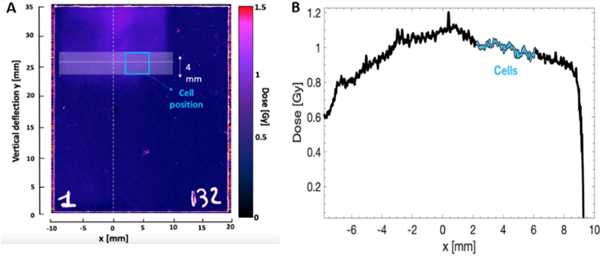
Figure 3. (A) Representative image of a RCF used during cellular irradiation scanned with the 12000XL Epson scanner and read with the Image J software. The position of the cells is highlighted by the light blue rectangle while the white horizontal line indicates the 10 MeV u−1 carbon ion position (the carbon energies dispersed vertically, with lower energies at the top of the image). (B) Transverse dose profile retrieved along the white line shown in figure 3(A) and averaged over 4 mm in the vertical direction (black line). The figure also shows the profile obtained in the 4 × 4 mm2 selected region corresponding to the cells position (light blue line). The zero of the X-axis corresponds to the center of the beam as indicated in figure 3(A).
Download figure:
Standard image High-resolution imageKnowing the energy spread at the cell position and the target-cell distance (300 mm) it is possible to retrieve the temporal duration of the carbon bunch reaching the cells within the ROI in figure 3(A) as shown in table 1.
Table 1. Minimum and maximum carbon energy within the ROI (9.5 ± 0.8 MeV) and the corresponding velocity and arrival time as calculated using the LISE++ code (Kuchera et al 2015).
| Min | Max | |
|---|---|---|
| Energy/nucleon [MeV] | 8.7 | 10.3 |
| Velocity [cm ns−1] | 4.06 | 4.35 |
| Arrival time [ns] | 7.39 | 6.88 |
Considering an average dose delivered of 1.0 ± 0.02 Gy and the pulse duration ∆t of about 500 ps obtained from the difference on the arrival times shown in table 1, a dose-rate of 2 ± 0.02 × 10⁹ Gy s−1 can be estimated.
3.2. DNA DSB damage and repair kinetics
The 53BP1 foci formation assay offers a simple method to study DNA DSB yields in individual cells at doses of order 1–2 Gy. As shown in figure 4(A), the mean number of 53BP1 foci per cell per Gy induced by x-rays at 0.5 h was 25 ± 1 while the value of carbon ions induced 53BP1 foci at this time point was 17 ± 1. At 24 h post-irradiation, significant amounts of x-ray induced DNA DSB damage was repaired as seen through reduction in the 53BP1 foci yield to 3.6 ± 0.4. However, the carbon-ion induced DNA DSB damages were repaired at a slower rate with a value of 11.5 ± 0.4 53BP1 foci per cell per Gy persisting at 24 h post-irradiation.

Figure 4. (A). DNA DSB damage induced by 1 Gy of 225 kVp X-rays or 10 MeV n−1 laser-driven carbon ions and repair kinetics studied through 53BP1 foci formation assay. 53BP1 foci are expressed as mean no. of foci per cell per Gy. (B) DNA DSB repair expressed as percentage of unrepaired DNA DSB obtained by normalizing the amount of unrepaired DNA DSB at different time points, to the amount of unrepaired DNA DSB observed at 30 min Error bars represent Standard deviation. The percentage repair kinetics over time is fitted with a two-phase decay analysis function (orange line- carbon ions and green line x-rays) available in Graph pad Prizm software version 9.
Download figure:
Standard image High-resolution imageTo obtain a better insight of the DNA DSB damage and repair process, we expressed the 53BP1 foci kinetics as percentage repair over the period of 24 h as shown in figure 4(B). Here we normalized the background-subtracted values of mean 53BP1 foci per cell per Gy at various time points to those induced at 30 min for both 225 kVp x-rays or laser-driven carbon ions. Considering the amount of induced damage at 30 min post-irradiation as 100%, the subsequent time points such as 1, 6 and 24 h show the progress of the repair process as seen through reduction in the percentage of unrepaired DNA DSB. E2 cells, due to their radioresistant nature, successfully repaired the low LET x-ray induced DNA DSB damage and at 24 h only about 6% unrepaired DNA DSB damages were observed. The carbon ion -induced complex damage persisted and at 24 h, at least 60% of the unrepaired DNA DSB damages were seen. The repair kinetics of the DNA DSB damage was fitted for both curves with an exponential two-phase decay equation (Groesser et al 2011, Plante et al 2019) using the expression

where Y is the number of foci, Plateau is the number of foci at infinite time
SpanSlow = (Y0-Plateau)*(100-Percent Fast)*.01
SpanFast = (Y0-Plateau)*Percent Fast*.01
Y0 is the foci number at time zero and X is time in hours
K Fast and K Slow are constants accounting for the fast and slow rate of repair, respectively.
Based on the two- phase decay fitting shown in figure 4(B), the value of the x-ray induced 53BP1 foci plateau was negligible compared to the 61% value observed for the laser-driven carbon ions. The percent fast repair for x-rays induced foci was 69% while for the carbon ions this value was 52%. The complexity of the DNA lesions induced by laser driven carbon ions affected the DNA DSB repair kinetics fitting equation parameters and the variation is clearly seen in rate constant ratio as well as in other parameters, as shown in supplementary table 1.
3.3. 53BP1 foci size comparison
In order to obtain an insight into the spatial features of the DNA DSB damage, we measured the area of both the x-ray and carbon ion induced 53BP1 foci at 24 h post- irradiation. We compared at least 100 53BP1 foci induced in the irradiated cells and clearly observed the impact of LET on the area of the 53BP1 foci. At 24 h post irradiation, the area of carbon-induced foci was 1.60 ± 0.07 μm2 while x-ray induced foci were smaller with an area of 0.63 ± 0.02 μm2. The difference between the area among the low LET x-rays and the high LET carbon ions was statistically significant with a p < 0.0001. Similar observations in the size variation of x-ray and carbon ions induced foci have been reported by other investigators (Oike et al 2016).
3.4. Relative foci induction
We further compared the effectiveness of laser-accelerated-carbon ions for foci induction relative to x-rays in terms of relative foci induction (RFI) as shown in figure 6. We observed an RFI value of 3.2 ± 0.2, which is similar to reported cell killing RBE of high LET carbon ions.
4. Discussion
We have presented here a pilot study demonstrating the feasibility of radiobiological investigations employing carbon ions delivered at dose rates of order 109 Gy s−1. Such dose rates have been demonstrated with protons (mostly using laser-driven methods), but never reached before with high LET heavier ions. This was obtained through the delivery of Gy-level carbon bursts of 400 ps duration at the location of the cell sample. The radiobiology of carbon at these extreme regimes is totally unexplored, and the effects of such ultrahigh dose rates on biological effectiveness are effectively unknown.
Based on the parameters achievable for the laser-driven carbon ions such as energy, dose and beam spot size (as shown in figures 1(A) and (B)), we chose a suitable radiobiological assay to measure DNA DSB damage using 53BP1 foci formation assay on a cell-by-cell basis using the irradiation scheme shown in figures 2(A)–(D). As some shot-to-shot variation of the dose parameters was inevitable due to the complexity involved in the generation of the laser-driven carbon ions, we used EBT3 film based dosimetry for every shot and defined the area for scoring the 53BP1 foci on individual slides to account for such dose variations as shown in figures 3(A) and (B). The dose rate independence and the possibility of localising the RCF film under the cells monolayers makes EBT3 Radiochromic film a very suitable dosimeter in the context of the present study.
As shown in figure 4(A) the carbon ions initially induced a smaller number of 53BP1 foci (17 ± 1) compared to the 25 ± 1 induced by the 225 kVp x-rays. The lower number of foci induced by laser-driven carbon may result from the fusion of several smaller, clustered foci to appear as a single large focus formed by the high LET carbon ions in contrast to the discrete foci formed by low LET x-rays. Due to the dense ionizing tracks and a wider penumbra due to secondary delta electrons surrounding the primary carbon ion track as described in (Ballarini et al 2008), the extent of DNA DSB damage is much wider for carbon than for the x-rays. The complexity of track structure also influenced the fidelity of DNA DSB repair as quantified through the unrepaired DSB damages. Over 24 h, while x-ray-induced 53BP1 foci reduced to background levels, the laser-driven carbon ions persisted and only about 40% of the damages were repaired by 24 h. The DNA DSB repair kinetics were adequately fitted by two-phase exponential decay kinetics and clearly indicated the variation in the repair parameters as shown in figure 4(B). Similar observations were also reported with other high LET ions where radiation quality affected both the spatial characteristics as well as the temporal features of the DNA DSB damage foci (Pastwa et al 2003, Antonelli et al 2015).
The larger 53BP1 foci area reveals the complexity of the DNA lesions induced by the high LET carbon ions (∼163 KeV μm−1 at the 9.5 MeV energy employed) since 53BP1 protein remains localised for a longer duration due to the unrepaired DNA DSB damages. As mentioned above, at such a high LET, secondary delta electrons are abundant in a track resulting in the formation of wider tracks and clustered DNA damages in contrast to the simpler damage induced by x-rays, as reported by several investigators (Desai et al 2005, Nakajima et al 2013). We also observed such variations in 53BP1 foci size in terms of area as shown in figures 5(A) and (B) at 24 h post-irradiation. Laser-driven Carbon ions induced foci had a significantly (p < 0.0001) larger area than x-rays induced foci, as shown in figure 5(B). For a proper radiobiological assessment of various radiation qualities, RBE is frequently used to describe the ratio of cell killing ability of a particular radiation type relative to conventional radiation such as gamma or x-rays. Although we did not perform any cell survival experiments, we have shown in figure 6 that relative foci induction (RFI) for laser-driven carbon ions was 3.2, which falls within the expected RBE range (1.2–3.5) of therapeutic carbon ions beams in glioblastoma cell lines (Tsuboi et al 2007). Although our results clearly show the expected effectiveness of carbon ions on DNA DSB damage and repair, based on the data presented in this manuscript it is difficult to unravel any potential dose rate effects from the expected damage complexity associated to the high LET of the carbon ions. Such an assessment would necessarily require comparative studies using conventional dose-rate carbon ions at similar energies, and this is certainly an objective for future work at a conventional accelerator facility.
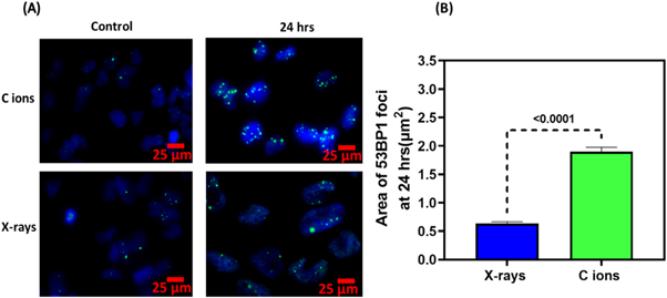
Figure 5. (A). Carbon ion and x-ray induced 53BP1 foci size comparison at 24 h after irradiation. (B) Mean area of 53BP1 foci induced by x-rays or carbon ions at 24 h expressed as μm2. For each datapoint, at least 100 foci were analysed using image J Analyze particle function. Unpaired Student's T test was used to calculate the statistical significance and the P values of <0.0001 is shown for each bar between x-rays and Carbon ions.
Download figure:
Standard image High-resolution image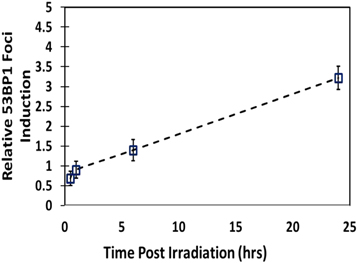
Figure 6. Relative 53BP1 foci induction values for 10 MeV n−1 laser-driven carbon ions relative to 225 kVp x-rays. For relative foci induction, the average values of carbon induced 53BP1 foci were normalized with the average value of the x-ray induced 53BP1 foci at each time point post-irradiation.
Download figure:
Standard image High-resolution image
The scope of this study was limited by the moderate carbon ion energies that could be reached reliably with our arrangement, as well as by the requirement to employ a relatively simple irradiation set-up which restricted the dose deliverable to the sample. Employing higher energy ions and doses would significantly expand the scope of the investigations, allowing for example studies under hypoxia (Chaudhary et al 2022) (which were not possible at 10 MeV n−1 as the particles were not energetic enough to penetrate a hypoxia chamber) or multi-Gy UHDR irradiations which may be used to assess whether FLASH-like effects extend to the dose rate regimes reachable with laser-driven particles. Higher carbon energies, up to 30 MeV n−1, have been demonstrated on the same facility (McIlvenny et al 2021) and could be already used for radiobiology experiments, provided an improved transport system is deployed, which refocuses the expanding carbon beam to deliver a sufficient dose to the cell sample. Suitable methods which have been demonstrated include systems of quadrupole (Bin et al 2012, Pommarel et al 2017) and pulsed solenoid magnets (Brack et al 2020), which also allow controlling the size of the irradiation field. Alternatively, compact target-based techniques, such as the helical coil method for beam collimation discussed in (Kar et al 2016) can be adapted to the transport of carbon ions and potentially lead to a significant increase in the dose deliverable. Furthermore, theoretical models predict that the energies of the carbon ions will scale up with the increase of the intensity and power of the laser drivers (McIlvenny et al 2020). For example, according to simple scaling predictions, supported by Particle in Cell simulations, carbon energies of order 80 MeV n−1 would be reachable by using short pulse PW systems (versus the ∼300 TW available on GEMINI). A stabilized RPA process on multi-PW systems (such as currently being developed or commissioned e.g. (Papadopoulos et al 2016, Radier et al 2022)) is predicted to lead to even higher energies (e.g., Qiao et al 2009). Finally, a different route for delivering high energy carbon ions at clinical energies, while maintaining the ultrashort temporal profile provided by laser acceleration, may be enabled by hybrid acceleration methods, where the initial laser acceleration phase is followed by injection in conventional accelerator elements (Antici et al 2011, Aymar et al 2020).
5. Conclusions
By exploiting recent progress in laser-acceleration of carbon ions and developing a compact irradiation set-up and dosimetry procedure, we have demonstrated, in a proof-of-principle experiment, the feasibility of carrying out investigations of the radiobiology of carbon at unprecedently high dose rates (exceeding 109 Gy s−1). In particular, we have used the DNA DSB damage and repair as a radiobiological endpoint in human GBM stem cells to perform comparative irradiations with 10 MeV n−1 carbon ions and reference x-rays. The results confirm the expected enhanced biological effectiveness of the carbon ions, associated to their significantly higher LET (160 KeV μm−1 versus 2 KeV μm−1 for the x-rays). The assessment of any specific dose rate effect would require the comparison with carbon ion data at the same LET and conventional dose rate, which is unfortunately not available at present. Nevertheless, the capability of performing radiobiology experiments using high LET radiation delivered in ultrashort bursts is currently unique to laser-driven experiments, and, with further development of the acceleration and beam delivery techniques, may be valuable to test novel irradiation regimes of potential future interest for radiotherapy.
Funding and acknowledgments
The authors acknowledge the funding received from the Engineering and Physical Sciences Research Council (EPSRC), through Grants EP/K022415/1, EPJ500094/1 and EP/P010059/1. This work has also been partly supported by project 18HLT04 UHD pulse, which has received funding from the EMPIR programme co-financed by the Participating States and from the European Union's Horizon 2020 Research and Innovation Programme. KMP acknowledges support from Brainwaves NI, Northern Ireland. Aaron McMurray acknowledges the funding support provided by Department for the Economy, Northern Ireland. Authors are also grateful to Prof Anthony J Chalmers, University of Glasgow and Prof Colin Watts, University of Birmingham, for providing the E2 cells.We further acknowledge the Biolab access and support provided by Dr. Asha Lata Doppalapudi at the ISIS Neutron and Muon source of Rutherford Appleton Laboratory, Didcot, Oxford.
Data Availability
The data for public access is available at: https://doi.org/10.17034/642ccd19-b32c-4682-809f-4f34a91c8d94.
Supplementary data (<0.1 MB DOCX)