

Abstract
Purpose. To develop and demonstrate an end-to-end assessment procedure for adaptive radiotherapy (ART) within an MR-guided system. Methods and materials. A 3D printed pelvic phantom was designed and constructed for use in this study. The phantom was put through the complete radiotherapy treatment chain, with planned internal changes made to model prostate translations and shape changes, allowing an investigation into three ART techniques commonly used. Absolute dosimetry measurements were made within the phantom using both gafchromic film and alanine. Comparisons between treatment planning system (TPS) calculations and measured dose values were made using the gamma evaluation with criteria of 3 mm/3% and 2 mm/2%. Results. Gamma analysis evaluations for each type of treatment plan adaptation investigated showed a very high agreement with pass rates for each experiment ranging from 98.10% to 99.70% and 92.60% to 97.55%, for criteria of 3%/3 mm and 2%/2 mm respectively. These pass rates were consistent for both shape and position changes. Alanine measurements further supported the results, showing an average difference of 1.98% from the TPS. Conclusion. The end-to-end assessment procedure provided demanding challenges for treatment plan adaptations to demonstrate the capabilities and achieved high consistency in all findings.
Export citation and abstract BibTeX RIS

Original content from this work may be used under the terms of the Creative Commons Attribution 4.0 licence. Any further distribution of this work must maintain attribution to the author(s) and the title of the work, journal citation and DOI.
1. Introduction
Most modern radiotherapy (RT) systems use some form of image guidance. For 3D imaging on linacs this will usually be performed using on-board kilovoltage cone beam computed tomography (CT). These x-ray based techniques are limited by their low soft tissue contrast, making it difficult to distinguish between certain tissues. A new development in image guided radiotherapy is the integration of magnetic resonance imaging (MRI) with a conventional linear accelerator. MRI provides a superior contrast between soft tissue types and allows for a more precise knowledge of locations and shapes of target volumes and all surrounding organs at risk (OARs) at the time of treatment, whilst providing no additional radiation to the patient from imaging. Simultaneous imaging and treatment enable online adaptive radiotherapy (ART) that utilises image guidance to re-optimise the originally prescribed radiation treatment plan, based on changes to the anatomy just prior to treatment. MR guided radiotherapy units could be the next development to revolutionise ART.
The Elekta Unity (Elekta AB, Stockholm, Sweden) (Lagendijk et al 2008, 2014, Raaymakers et al 2009) is such a unit, using a high field MRI integrated with a 7 MV linac that can adapt reference treatment plans using online MRI images obtained of the patient on the treatment couch. The Elekta system uses two approaches to ART: adapt-to-position involving a translation of the whole patient and adapt-to-shape involving movement of the internal structures relative to the rest of the patient anatomy and which can be both rigid and deformable.
The most rigorous assessment of the accuracy of the adaptive treatment planning techniques requires the use of end-to-end testing where the complete treatment process, which would be experienced by a patient, will be undergone by a physical phantom. This will provide a method of evaluation for the uncertainty of the chain in one process.
Prostate cancer is a common cancer and one of the most studied disease sites related to online ART. Challenges observed with this treatment site include changes in shape and position of the prostate both between fractions, and during fractions as a result of bladder filling and rectal distension (Dawson et al 1998, Mah et al 2002). In addition to the target volume changes, the number of OARs in close proximity make it a challenging site to focus on for assessing the accuracy of ART.
The purpose of this work was to develop and demonstrate both an end-to-end procedure for assessing the accuracy of ART within an MR guided system, and a prototype pelvic phantom for use in the procedure. The phantom was designed and developed through a combination of additive and subtractive manufacturing, allowing imaging in both CT and MRI plus dose measurement in structures inside the phantom. As more radiotherapy departments are beginning to utilise the capabilities of MR guided systems, quality assurance procedures for verifying individual components are quickly becoming more established (Mittauer et al 2019), with several being modified versions of those used on conventional radiotherapy delivery and imaging systems, as well as a number of additional tests being required for the unique challenges specific to MR guided systems (Dorsch et al 2019); however, there is an increasing need for end-to-end tests for the complete workflow. Recent studies (Hoffmans et al 2020, Stark et al 2020) have been made developing end-to-end tests on adaptive workflows in MR guided systems, but this work aims to further investigate specific types of adaptation by allowing a more customisable range of target volume deformations, including significant target displacements and shape changes during treatment.
2. Methods
2.1. Phantom design considerations
The requirements of the phantom were: (i) it contained a target volume, specifically aiming to mimic the prostate, and all appropriate OARs related to prostate treatment; (ii) the target could mimic translations and shape deformations accurately and repeatably, (iii) the phantom allowed for measurements of the delivered dose distribution, (iv) absolute dose could be measured, (v) the phantom was robust and reasonably compact for transportability to allow dose measurements at different centres, (vi) good visibility and realistic signal contrast was achievable in both CT and MRI, and (vii) no imaging artefacts were generated in either imaging modality.
2.2. Phantom construction
In this description the components of the phantom are divided into three categories: structural components, imaging components, and dosimetric components. The majority of the components discussed here were created with the aid of 3D printing technology. The main reasons for this were to reduce costs for the development procedure, allowing custom securing devices to be quickly created for various dosimeters, and an increased freedom into the shape of components, making it possible to alter designs to secure a wide range of dosimetry devices. While this has been beneficial for the development, a final production of the phantom would not have to be created using 3D printing, with more traditional manufacturing offering advantages once a design has been shown to be satisfactory with no further modifications required.
The main structural component is a large outer box of similar dimensions to the pelvic region of the body. This was constructed from a 5 mm layer of polylactic acid (PLA), fillable with up to 10 litres of water to create the homogeneous background signal within the phantom. The phantom dimensions are displayed in figure 1. Both the superior and inferior ends of the phantom body possessed large dovetail grooved slots, allowing for easy location of internal structures. These were used to secure anatomical structures and dosimeters. After structures were inserted into the phantom it was filled with water and a bulkhead/compartment system was inserted, as shown in figures 2(a) and (b). This was required to reduce water perturbation resulting from movement of the phantom, which leads to MR imaging artefacts.
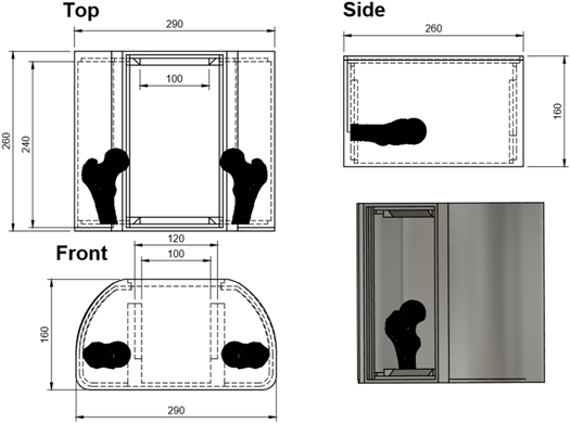
Figure 1. Technical drawing of phantom body, into which all internal components were secured, showing a coronal view (upper left), sagittal view (upper right), a transverse view (lower left), and a 3D rendering (lower right).
Download figure:
Standard image High-resolution image
Figure 2. The phantom bulkhead structure/compartment system is shown separately, and setup inside the phantom body in (A) and (B) respectively. (C) shows the three prostate volumes made of ballistic gels, with the realistic shape and sized prostate on the left, spherical design in the middle, and enlarge realistic design on the right.
Download figure:
Standard image High-resolution imageThe first imaging component within the phantom was the prostate volume, which was used as the target for all treatment planning and was moved to a range of positions between imaging acquisitions to test the ART capabilities of the MR linac system. An in-detail description for the creation of this mould is given in section 2.3.
Following an investigation into the MRI and CT properties of a range of target materials, ballistic gel (Defensible Ballistics Ltd, Kent, England) was used as a target, creating a clear, artefact free image in both modalities. The target volume has a density ≈1.05 g c.c.−1, and a Hounsfield unit value of ≈60, making it easily visible within CT against the surrounding water. Additionally, this material offers clear visibility with no chemical shift artefacts visible for a range of MR sequences commonly used for prostate RT imaging. While studies have found similar ballistic gels to be representative of soft tissue dosimetrically (Steinmann et al 2018), no such study has yet to be made from the manufacturer of the gel used in this study; however, with the intension to replace the target volume with various dosimetry devices for irradiation, this was not necessary at the current stage of development. During the investigation into suitable materials to be used for the target, it was found that ballistic gels can suffer from dehydration and therefore shape inconsistencies if stored incorrectly; however, as the targets were submerged within water when in use, and showed no shape degradation between short experiments using our storage, this downside was outweighed by the excellent imaging characteristics and the ease of production with no hazardous gases released during the curing stage, which was the case for a number of alternative gels investigated.
For imaging, the target volume was located using the dovetailed grooves, which allowed accurate translations in all directions by choosing different groove positions. These translations were made manually by either inserting or removing spacers. Shape deformations were also made by removing and replacing the target with a target of the same volume, but a different shape as shown in figure 2. The first of the targets used was generated from a patient MRI scan, with a volume of 20 cm3 to match the size of an average prostate (Edwards 2008). The second target had the same volume, but a spherical shape. Figure 2(c) displays both of these, in addition to a third volume with the same shape as the realistic target but magnified to have a volume of 30 cm3.
The other imaging components within the phantom represented OARs. These were kept in the same position for all studies. The first OAR set was two femoral heads positioned on the left and right of the phantom body, which were created out of 100% infill 3D printed PLA and appeared as low signal areas in MRI and as high signal in CT scans. With a density of ≈1.3 g cm−3, PLA has a density between cancellous and cortical bone, making it suitable to represent a femoral head as a single material. While these did not currently offer any advantage for dosimetry, the purpose of their inclusion was to provide a consistent OAR to avoid in the dose objectives of the treatment plan. The final two OARs, the rectum and bladder, were made using 3% agar gel doped with a 1 mmol l−1 of CuSO4, held in position using a thin PLA shell. The rectum possessed a hollow centre and the bladder was split into two separate sections, to allow the insertion of a dosimeter into each when required; however, the treatment plan contours both OARs as solid volumes. The positions of these volumes are shown in figure 3.
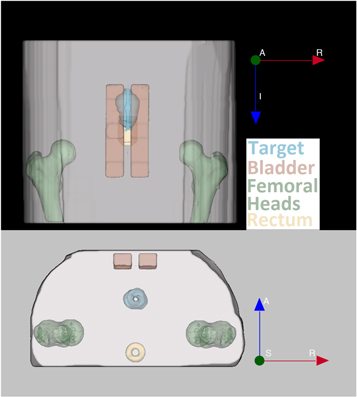
Figure 3. Position of the three OARs and target volume when secured into the phantom, with a coronal view (top) and an axial view (bottom). The target volume, bladder, femoral heads and rectum are displayed in blue, red, green and yellow respectively.
Download figure:
Standard image High-resolution imageThe design for the positions of the OARS has spaced them apart to allow sufficient room for extended anterior–posterior movement of the target volume without requiring changes to the OARs.
The third set of phantom components were those used for dosimetric purposes. To ensure high positional accuracy and due to many dosimetry methods requiring replacement of dosimeters between irradiations, a sequential method of conducting dosimetry was chosen. This meant that the user was required to replace the target volume with each of the dosimeters individually between measurements of plan adaptations. As with the target volume positioning, the dovetailed grooves were used to hold the dosimeters in place. The dosimeters were two strips of EBT3 gafchromic film (Ashland ISP Advanced Materials, NJ, USA) with dimensions of 20.3 cm × 7.8 cm which allowed dose distributions to be measured for two central slices in the sagittal plane, with one sheet positioned directly through the centre of the phantom, as shown in figure 4, and the other offset by 5 mm to the patient right. The offset film does not appear within figure 4 as it is in a different slice. Gafchromic film was chosen due to the presence of the magnetic field only having a minimal effect on the measured dose (Billas et al 2019). Although a static magnetic field presence has been shown to not significantly change the dose readout of gafchromic film, Reyhan et al (2015) found an over estimation of the dose measured using gafchromic film with an increased specific absorption rate on film due to the MR pulse sequences. That study however, used EBT2 film instead of EBT3 used here. While studies have not yet been made on any SAR effect within a 1.5 T MRI, (Barten et al 2018) found no difference for EBT3 film within a 0.35 T. In addition to this, the experimental setup used for this experiment did not involve exposing the film to any unnecessary SAR as film was only added to the phantom once the imaging had been completed. This allowed the dose distribution delivered in and near the target volume, to be measured. To measure doses in the OARs, a 20.3 cm × 2 cm strip of Gafchromic film could be used to measure the dose distribution through a central sagittal slice of the bladder and a semiflex ionisation chamber was placed in the centre of the rectum, using a threaded screw to secure the position. The positions of all dosimeters are shown in figure 4. All gafchromic film measurements were used as absolute dosimetry, with no normalisation conducted for comparisons with the treatment planning system (TPS) calculations.

Figure 4. Central sagittal slice of the phantom, showing the positioning of: strip of gafchromic film used for the target volume (Labelled Film(Target)), strip of film used for the bladder (Labelled Film(Bladder)), the alanine holder with the 9 alanine pellets shown in red, and the semiflex ionisation chamber positioned within the rectum. Superior–inferior and anterior–posterior directions are shown.
Download figure:
Standard image High-resolution imageAn additional absolute dosimetry method was carried out using a Farmer chamber shaped holder containing 9 alanine pellets, 5 used for measurements and the additional 4 pellets acting as spacers (Billas and Duane 2018). Alanine was chosen as it has also been shown to experience a minimal effect from the magnetic field on the measured dose (Billas et al 2020), in addition to being a robust detector that does not require electronic readout which may be a problem in an MR system. The inclusion of this second absolute dosimetry method was to verify the absolute dose measurements obtained through using gafchromic film, but was limited to only the first treatment plan adaptation experiment due to the reading out procedure being both costly and time-consuming. Due to positional overlap with the gafchromic film in the target volume, this requires the treatment plan to be re-delivered, with the film component removed and replaced with an alanine pellet holder. As shown in figure 4, these pellets were positioned through the centre of the target volume and could be re-positioned to match all target volume positions used.
Figure 4 shows a sagittal slice of the phantom, as well as the positions of the gafchromic film, the alanine pellets and the semiflex ionisation chamber.
2.3. Creation and use of the target volume mould
Figure 5 shows the process used for creating the gel prostate targets starting with MR images. While the final stages shown use ballistic gel for the production of the target, the same process was also used during the testing of alternative materials. Each of the steps displayed in figure 5 are explained below.
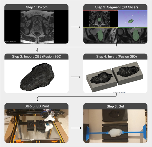
Figure 5. Workflow for creation a 3D printed mould and gel target volume based on a patient's MR images.
Download figure:
Standard image High-resolution imageStep 1: This target design was based on published MRI patient data (Dikaios et al 2015), ensuring a realistic prostate shape and volume representing a patient undergoing prostate radiotherapy.
Step 2: The prostate gland structure was segmented manually using 3D slicer (Fedorov et al 2012). This segmentation was then made into a 3D model which could be exported as an OBJ file.
Step 3: The OBJ file was imported into Fusion 360 (Autodesk Inc., San Rafael, CA) with minimal smoothing applied at this stage to reduce the sharp edges arising from the MRI slice thickness while limiting the shape change.
Step 4: An inverse of the prostate body was created to act as a mould. Modifications were made to this mould within Fusion360 to secure the supporting rod that will hold the target within the phantom, in addition to a hole to be used for injection of gels.
Step 5: The rectangular mould was 3D printed with a resolution of 0.1 mm on a Creality Cr-10s (Shenzhen Creality 3D Technology Co. Ltd, Shenzhen, China)
Step 6: The gels were prepared as described by the manufacturer, allowing them to be injected into the plastic mould. Weight measurements of the target volume were made after curing and removing from the mould to ensure consistency. Based on the design, this mould was reusable for all repositions of the prostate currently used.
2.4. Elekta MR-linac
The end-to-end test procedure passes the phantom through the complete radiotherapy workflow. The Elekta Unity system integrates a 1.5 T MRI (Philips Healthcare, Best, The Netherlands) and a 7 MV standing wave linac, which received FDA 510(k) clearance in December 2018 and CE mark in June 2018. The purpose of this integration is to detect anatomical changes from inter-fractional and intra-fractional motion through repeated MR images. MR images are being used to adapt each treatment fractions and perform optimal treatment. All treatment plans for use in the Elekta MR-linac were created utilising the Monaco TPS version 5.40 (Elekta AB, Stockholm, Sweden).
2.5. End-to-end test procedure
The first stage of the assessment procedure was to obtain a pre-treatment CT scan of the phantom which was used for reference treatment planning. Using a Mediso AnyScan SCP (Mediso, Budapest, Hungary) the pre-treatment scan was taken with a slice thickness of 1.25 mm, and a resolution of 1 × 1 mm2.
In the next step, a pre-treatment MR image was made of the phantom using the 1.5 T MRI scanner in the Elekta Unity system. For both co-registering with the CT and for all treatment plan adaptations, a standard pelvic MRI sequence was used. The 3D, T1-weighted, fast-field echo sequence was used with a slice thickness of 2 mm, repetition time of 11 ms, and echo time of 4.605 ms, with the use of 2 averages to limit any water motion artefacts still arising due to the large volume of water within the phantom.
The pre-treatment CT and MRI scans were co-registered, using rigid registration in Monaco, with the target and OAR volumes contoured manually. Using a prostate treatment plan template in Monaco, a 7-beam intensity modulated radiotherapy plan was designed to deliver 6800 cGy in 2 Gy fractions. In this procedure, each treatment plan adaptation was considered as a single fraction of the complete treatment. With the type of treatment plan adaptations used throughout this experiment, the number of segments were kept consistent; however, the monitor units delivered for each plan will vary. The beams angles were also kept consistent, with the 7 beam angles being: 30°, 81°, 132°, −177°, −126°, −75°, and −24°. Figure 6 displays an example of the adapted treatment plan used for the third experiment, described in table 1, depicting the dose distribution through a central axial slice of the phantom.
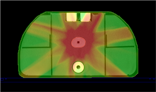
Figure 6. Axial slice of the adapted treatment plan used for an adapt to shape experiment, displaying the bladder (contoured in yellow), the prostate (contoured in red), and the rectum (contoured in green).
Download figure:
Standard image High-resolution imageTable 1. Phantom configurations used in this study.
| Experiment number | Target volume displacement (X, Y, Z)/mm | Total 3D vector shifts (mm) | Target volume shape description | Type of treatment plan adaptation used |
|---|---|---|---|---|
| 1 | 0, 0, 0 | 0 | Realistic/CT based target shape | Adapt to position |
| 2 | 0, 0, 15 | 15 | Realistic/CT based target shape | Rigid adapt to shape |
| 3 | 0, 30, 25 | 39 | Realistic/CT based target shape | Rigid adapt to shape |
| 4 | 0, 0, 0 | 0 | Spherical | Deformable adapt to shape |
| 5 | 0, 30, 25 | 39 | Spherical | Deformable adapt to shape |
For the ART study, physical changes were made to the phantom by moving and/or changing the shape of the target volume. MR images were then acquired and used as input to the adaptation strategy.
While there are two main categories for treatment plan adaptation types using the Elekta system, adapt-to-position and adapt-to-shape, this study further differentiated between types of ATS. From a TPS software point of view, both types of ATS adaptations are the same; however, as the phantom configurations were significantly different, they have been referred to as separate techniques from here onwards. The three types of treatment adaptation used were:
- (i)ATP: Assessment of the adapt to position technique was conducted using the original position of the phantom on the MRI patient couch, rigidly registering the pre-treatment CT with the online MR image.
- (ii)RATS: The first type of adapt to shape technique investigated is referred to as rigid adapt to shape (RATS) technique. RATS corrected for changes to the internal anatomy of the patient or phantom, where the target volume was translated while the shape and rotation remained consistent. This required registration between the pre-treatment and online MR images; the target volume was outlined by the planner and the contours were shifted to account for target volume translations, before reoptimizing the plan. This adaptation strategy allows the patient and target volume contours to move independently, unlike in the ATP strategy.
- (iii)DATS: The final adaptation investigated was deformable adapt to shape (DATS). This built upon the RATS technique by also including target volume deformations. Due to the significant shape deformations used, this required amendments to the target volume contours to be made.
Table 1 shows the different phantom configurations used in this study, including which treatment plan adaption was used, the shape description of the target volume, and the total displacement undergone by the target volume relative to the original position in the reference plan. Although the target volume was only moved in a combination of superior–inferior and anterior–posterior directions, referred to from here on as the Z axis and Y axis respectively, it is also possible with this phantom to move the target in the X axis but this was not included to focus on displacements most commonly observed during prostate treatment (Sihono et al 2018).
The total 3D vector shifts for the target volume of 15 and 39 mm were chosen to explore the largest changes in target position that can be corrected for with ART. While these challenging treatment scenarios are not representative of those observed in prostate treatment, it does allow for a more difficult challenge for the system to overcome.
2.6. Dosimetric evaluation
2.6.1. Gafchromic film
For each of the treatment plan adaptions displayed in table 1, two sheets of film were irradiated, as discussed is section 2.2. Upon completion of the experiment, all sheets of film, including calibration strips, were read out 48 h after irradiation using an EPSON 1000XL scanner at 75dpi. A standard film calibration procedure was conducted for the batch of gafchromic film used, applying the single channel calibration conversion to each film using ImageJ (Schindelin et al 2012). Marroquin et al (2016) found that the film response is more sensitive for the dose range of 0–6 Gy when scanning with the red channel, in addition to calculating a total dose uncertainty for the range of 3.2% for red channel calibrated film; therefore, the red channel was chosen to be used for the calibration in this experiment due to low dose range being used. To reduce potential under estimation of the dose, the time delay between all irradiations and read outs of the film were kept consistent at 48 h.
To assess the dosimetric accuracy of the adapted treatment, all dose measurements were compared with the relevant adapted treatment plan dose distribution (correcting for daily output), using the 2D global gamma analysis evaluation method (Low et al 1998). Both sheets of film used for each experiment were secured onto a specifically designed holder using a set of 3D printed pins. As the midpoint between the centre of the 6 pin holes used for the centrally located sheet of film was designed to align with the middle of the phantom, this made it possible to quickly manually register the geometric location of the measured dose to the calculated dose with an uncertainty of <1 mm. Analysis was performed using PTW Verisoft software (PTW, Freiburg, Germany). For this analysis, criteria of 3% dose difference /3 mm distance to agreement and 2%/2 mm were used, with a dose threshold applied to doses less than 10% of the maximum. While the use of low dose thresholding does not largely impact global gamma analysis pass rates (Song et al 2015), a 10% minimum dose threshold was chosen to remove irrelevant low-dose film regions far from the target volume. No additional normalisation techniques were applied during this analysis.
2.6.2. Alanine
The alanine measurements were made, as described in section 2.2, with 5 pellets measured per irradiation. To minimise uncertainty associated with the alanine readouts, a dose above 10 Gy was required (Helt-Hansen et al 2009). At this dose level, the uncertainty associated with the measurement is 1.7% (uncertainty k = 2), and the pellet-to-pellet reproducibility is 1% (k = 2) (Sharpe and Sephton 2006). As these measurements were conducted with the gafchromic film sheets removed, the adapted treatment plans were delivered 5 times consecutively to achieve this dose, with the final absolute dose measurement then being divided by 5 to provide the result for one fraction. The batch of alanine pellets used were calibrated and read out by the UK National Physical Laboratory's dosimetry service. The dose measurements received from each of the alanine readouts were compared individually with the predicted dose values from the TPS, with correction for daily output. The alanine measurements have had a correction factor (Billas et al 2020) of 0.7% applied, due to the 1.5 T magnetic field experienced. This is required due to the bevelled edges of each alanine pellet leaving a small airgap between the pellets and the holder which will lead to the electron return effect. For this study, alanine measurements were only conducted on the first experiment.
3. Results
3.1. CT and MR images of the phantom
A key requirement of the phantom is that the MRI and CT images are both artefact free, with all volumes possessing enough contrast and well-defined boundaries to aid with consistent contouring. Figure 7 displays an example of both a CT image of the phantom, used for creation of the reference treatment plan, and an MR image, used for the treatment plan adaptation. Discussion of these images is provided in section 4.
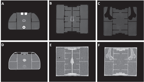
Figure 7. Axial (A), and (C) and coronal (B), (C), (E), and (F) view of the T1 weighted MRI (A)–(C) and CT (D)–(F) images of the phantom.
Download figure:
Standard image High-resolution image3.2. Gafchromic film measurements
Figure 8 displays the measured dose map from the off-centre sheet of gafchromic film for experiments 1 and 5, in addition to the corresponding calculated dose map and 2D gamma index map. These gamma index maps were generated using a distance to agreement of 2 mm and a dose difference of 2% to show the failure points for the most critical analysis conducted.
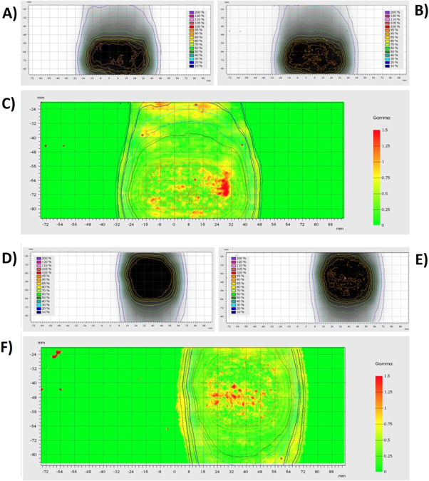
Figure 8. TPS Calculated dosimetry maps (A) and (D) and film measured dosimetry maps (B) and (E) for the first adapt to position experiment (A)–(C) and the final adapt to shape experiment (D)–(F) conducted. The agreement between each of the dose maps is shown by the Gamma index maps (C) and (F). The gamma index maps use a distance to agreement of 2 mm, and a dose difference of 2%.
Download figure:
Standard image High-resolution imageThe gamma analysis pass rates for both sheets of film in all five treatment plan adaptations tested are given in table 2. These results are based on measurements from the gafchromic film strips, with the gamma evaluation pass rates shown for both strips of film individually, in addition to the mean pass rate for each experiment.
Table 2. Gamma evaluation pass rates for each of the investigated treatment plan adaptations, with the mean pass rate on the righthand side combining the results from the two strips of film used in each adaptation.
| 2D gamma analysis | 3%3 mm | 2%2 mm | Mean pass rate | ||||
|---|---|---|---|---|---|---|---|
| Type of adaptation | Vector displacement (X, Y, Z) mm | Middle | Right | Middle | Right | 3%3 mm | 2%2 mm |
| ATP | 0, 0, 0 | 99.60% | 99.50% | 93.00% | 97.10% | 99.55% | 95.05% |
| ATS(Rigid) | 0, 0, 15 | 97.40% | 99.70% | 92.30% | 97.70% | 98.55% | 95.00% |
| ATS(Rigid) | 0, 30, 25 | 99.80% | 99.40% | 97.30% | 95.80% | 99.60% | 96.55% |
| ATS(Deform) | 0, 0, 0 | 97.50% | 98.70% | 91.20% | 94.00% | 98.10% | 92.60% |
| ATS(Deform) | 0, 30, 25 | 99.70% | 99.70% | 97.20% | 97.90% | 99.70% | 97.55% |
| Average | 99.10% | 95.35% | |||||
3.3. Alanine measurements
Table 3 displays the calculated alanine results from this study, compared with the daily output corrected predicted dose value from the TPS. Each of the % differences are calculated based on the absolute values before rounding the dose measurements to 3 significant figures.
Table 3. Measurements from alanine dosimetry compared with daily output corrected calculated values from the TPS, including the average doses and difference.
| Alanine measured dose/Gy | TPS predicted dose/Gy | % Difference | |
|---|---|---|---|
| 2.49 | 2.47 | 0.80 | |
| 2.51 | 2.46 | 1.96 | |
| 2.51 | 2.44 | 2.82 | |
| 2.49 | 2.43 | 2.41 | |
| 2.49 | 2.44 | 1.91 | |
| Average (Mean) | 2.50 | 2.45 | 1.98 |
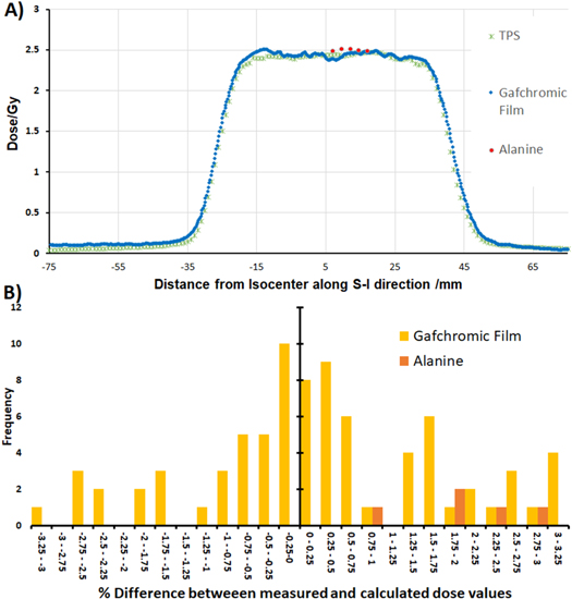
A profile through the centre of the phantom from the first fraction, comparing both the alanine and gafchromic film measurements with the TPS calculations, is shown in figure 9(a) with a histogram of the percentage differences between the measured and calculated doses for alanine and film, relative to the global maximum, shown in figure 9(b). The percentage differences shown are from calculations made on the plot profile, which used the grid spacing from the TPS of 1 mm and removed all doses below the 10% threshold as with the gamma analysis to focus on the high dose area.
Figure 9. (A) Plot profile of the dose distribution, comparing the gafchromic film measurement (blue), alanine measurements (red) and treatment planning system calculations (green). (B) Histogram of % differences, relative to the global maximum, between the measured and calculated dose along the plot profile for gafchromic film measurements (yellow) and alanine (orange)
Download figure:
Standard image High-resolution image
4. Discussion
The goal of the work in this paper was to demonstrate a methodology developed for conducting an end-to-end test on an MR guided radiotherapy system. This required a semi-anthropomorphic phantom that could possess realistic x-ray and MR appearance, and allow for controllable and measurable changes to the phantom consistent with movement and deformations of internal anatomy in a prostate cancer patient.
The procedure developed for utilising the phantom has only been designed to conduct an end-to-end study on the accuracy of ART. Due to this, it is still required to conduct regular quality assurance on the system before any end-to-end analysis can be made as results will only show how accurate the complete radiotherapy chain is. Quality assurance procedures were conducted on the Elekta Unity to ensure the geometric distortion and isocentre alignment accuracy were sufficient before the end-to-end experiment could be made.
Imaging of the phantom using both modalities was essential. High contrast between components and well-defined boundaries is needed to ensure that contouring of organs for treatment planning can be conducted easily, reducing the potential for human error and allowing the focus of the analysis to be on the accuracy of the system itself, as well as for assisting in co-registration. As shown in figure 7, the target volume possesses a high signal intensity in both MRI and CT, with no obvious imaging artefacts generated. As each of the volumes within the phantom were made of a single material, each organ is displayed as a very homogenous region in both sets of images. While a more realistic view would be to create a more complex structure, this simplified anatomical design allows for more repeatable contouring for treatment planning, in addition to quick identifiability of any potential Gibbs artefacts arising in MRI scans. As contouring of the target volume was greatly assisted by the high signal intensities, this also allowed for a final investigation into any potential shape degradation that could have occurred from dehydration of the target by comparing the volume of interest for each adaptation. The MR signal intensities of the rectum and bladder OARs are both very high due to the concentration of agar and CuSO4 used in preparation, with the current signal intensity ratio between water, target and OAR being ≈1:2:5. While adjustments to the doping could be made to provide a more realistic contrast, with a wide range of T1 and T2 relaxation times achievable through varying the concentrations of agar or copper sulfate (Bucciolini et al 1989), the purpose of this study at this stage was not to assess the accuracy of contouring, and therefore benefits from the significant contrast between each volume. In addition to this, the high concentration of agar assisted with the rigidity of the volumes and further prevented dehydration related shrinking. Within the CT images of the phantom, the gels used for both of these OARs appear very similar to water. For this reason, the 3D printed shells used to hold the OARs in position were necessary as they allow the user to clearly identify each region when co-registering with the MRI. Finally, the femoral heads within the phantom appear as a void within the MR images due to no signal being generated by the plastic, whereas they appear very brightly within the CT images. As these volumes possess a complex structure and well-defined boundaries in both modalities, they allow for an accurate method of co-registering the images.
Imaging of the ballistic gel target volume suggests it to be a very suitable soft tissue or tumour substitute. While the material was found to deteriorate due to dehydration if left out at room temperature for a few days, current investigations have not observed any shape inconsistencies for ballistic gel that would occur over the course of an experiment, with correct storage also prolonging the usable lifetime when required for transporting. Due to the importance of shape consistency in target volumes, the current methodology advises storing all targets within an airtight container in a refrigerator until the day of each experiment to avoid dehydration or potential bacteria growth. When the target volume is removed from its storage for positioning within the phantom, the target is completely submerged within water meaning it will not be in dehydrating conditions. Currently no evidence has been observed to provide concerns of this shape degradation occurring during the experiment, with weight measurements of the target, and measurements of the volume of interest from the MR images all showing consistency. As the phantom is still undergoing further developments, additional investigations are being made into the potential gels that could be substituted into the phantom as an alternative target volume. Dosimetric gels (Baldock et al 2010) have been highlighted as a potential fit for the overall aims, while not significantly changing the production method use. Dosimetric gels could additionally provide the opportunity to conduct 3D dosimetry for the target volume to further support the 2D and 1D dosimetry method currently being used.
The gamma analysis comparing the measured results from the gafchromic film with each of the adapted treatment plans investigated showed a very high agreement with an average pass rate of 99% and 95%, for criteria of 3%/3 mm and 2%/2 mm respectively. These pass rates were consistent for both shape and position changes. The high agreement and consistency of results shown for all position and shape changes in this investigation demonstrates the dosimetric accuracy of the complete ART workflow of an MR guided system. The gamma failure points, as highlighted in red in figure 8, generally appear randomly throughout the high dose region, with the isodose lines for both calculated and measured doses showing strong agreements in the high dose gradient region. This suggests the gamma index failures were not as a result of an incorrect target location or shape. A comparison of these pass rates with results reported in the similar studies of the accuracy of prostate treatment (Budgell et al 2011, Clark et al 2014, Jurado-Bruggeman et al 2017) demonstrates the high level agreement between the treatment plans and measured results, with similar gamma pass rates achieved while utilising 2D analysis. As the investigations discussed here only used two sheets of parallel gafchromic film for the target volume, 2D gamma evaluation was the more appropriate analysis for this situation; however, phantom components are available to create a pseudo 3D dose distribution by either combining the sagittal sheets of film with an additional film in the coronal plane, or by increasing the number of films used in the stack. While the quantity of sagittal film sheet used would be limited due to the dosimetric properties of gafchromic film not mimicking tissue, the inclusion of three additional sheets could provide a sufficient resolution in all planes to cover the target volume while only adding <1 mm thickness of gafchromic film to the experimental setup. This method would also not significantly increase the time to conduct an end-to-end study which is of great importance within a clinical environment.
The confidence in results is further supported by the close agreement with the alanine to both the TPS and film measurements, shown in figure 9, with a mean difference between calculated and measured doses being 1.98%; however, alanine measurements were only conducted for the first experiment. While the difference between these results were larger than expected, as displayed in figure 9(B), all alanine measurements reported a higher dose than both the film measurements and TPS calculations, suggesting this could be a systematic error arising from the calibration. This trend would need to be further investigated in future work by conducting alanine measurements on an increased number of experiments.
A number of studies have been made by other groups investigating methods of analysing ART within an MR guided system, with the main differences in design being the type of changes made to the target volume, and the use of alternative dosimeters, such as dosimetric gels, thermoluminescence dosimeters (TLDs), and scintillation detectors (Ehrbar et al 2019, Elter et al 2019, Pappas et al 2019, Mittauer et al 2020). The main alternative to film for multiple dimension dosimetry is the use of dosimetric gels, which benefit from their ability to measure 3D dose distributions. While Lee et al (2017) found hot spots causing an increase of dose at the air-gel boundary of up to 40% and 30% for ferrous oxide xylenol orange gel and Presage respectively, this issue arising from air surrounding the dosimeters is also faced with gafchromic film and was solved in this experiment by completely submerging the dosimeters within water. This could be a viable option as an addition to the phantom for future experiments, to be used in combination with the current dosimeters, as it would allow 1D, 2D, and 3D dosimetry to be conducted; however, while gafchromic films are already widely used and can be processed in all hospitals, dosimetric gels require some level of expertise to both read out and produce. A main benefit for the current design, making use of ballistic gels for imaging and gafchromic film for absolute dosimetry, has been that all preparation of gels can be conducted in-house with no complications, as well as gafchromic film being readily available and easy to store between experiments. As observed in the studies utilising the alternative one-dimensional detectors, it is possible to easily implant the detectors within a target volume, allowing for a more simultaneous workflow than the sequential setup used in this study. While TLDs will still require a replacement between irradiations, making their use less suitable for conducting multiple ART experiments in a session, scintillation detectors can be used for time-resolved dosimetry. Real-time readouts from an array of scintillation detectors could be very beneficial for future evolutions of the phantom in this study as it would allow for dose measurements within a dynamically deforming target volume; however, it would require very accurate localisation of all detectors at the time of each irradiation.
The additional use of alanine as a second absolute dosimetry measurement method in this study offers further advantages to this procedure. With intentions to progress this study into a multi-centre audit, a particularly robust detector, which retains the low uncertainty achievable with ionisation chambers, is very beneficial. While the dose response of ionisation chambers is affected due to the ERE within the air cavity, studies have been made to calculate correction factors (Smit et al 2013) to overcome this change; however, this will still result in an increased uncertainty. Dosimetry measurements using alanine pellets will also be influenced by the ERE, as alanine pellets are not waterproof so require a holder where air cavities will remain due to the tolerances; however, this effect is greatly reduced compared with ionisation chambers as the air cavities are significantly smaller. A small correction factor of 0.7% is applied to alanine measurements (Billas et al 2020) taken within a 1.5 T magnetic field.
For this study, the phantom was designed so that only the target volume would move, keeping the rest of the volumes rigid throughout the workflow. The reasoning for this design decision was to keep the focus on overcoming the significant target volume displacements and deformations, without adding the additional variable of OAR deformations. As the results of this study have shown very good agreement, one of the future plans for the phantom is to implement changes to the bladder and rectum at the same time as the prostate. This will allow the positioning within the phantom to be more realistic, with the spacing between each of these volumes greatly reduced. In addition to the inclusion of OAR adaptations, the focus will be moved onto smaller shifts in position for the target volume, aiming to replicate intrafractional motion observed during prostate treatment. With the additional phantom configurations added, the aim will be to conduct a multicentre audit using a full framework developed from this procedure to investigate the consistency of adaptive treatment at multiple MR guided radiotherapy sites.
While this work has focused on use with the Elekta Unity system, there is a need for end-to-end assessment procedures for online ART on all variations of current generation radiotherapy systems. As this system has been shown to work within a high field MRI, the same end-to-end workflow could also be conducted for all MR guided systems currently available, as well as more conventional IGRT systems.
To conclude, a framework using a 3D printed semi-anthropomorphic pelvic phantom has been developed to conduct an end-to-end test that can assess the accuracy of ART within an MR guided system. The phantom has demonstrated good flexibility in the range of treatment plan adaptions that can be investigated and provided a promising groundwork to build upon for more anatomically correct displacements that would be observed clinically, as well as extreme adaption situations.