
Abstract
Artificial microswimmers, i.e. colloidal scale objects capable of self-propulsion, have garnered significant attention due to their central role as models for out of equilibrium systems. Moreover, their potential applications in diverse fields such as biomedicine, environmental remediation, and materials science have long been hypothesized, often in conjunction with their ability to deliver cargoes to overcome mass transport limitations. A very efficient way to load molecular cargoes is to disperse them in a liquid compartment, however, fabricating microswimmers with multiple liquid compartments remains a significant challenge. To address this challenge, we present a modular fabrication platform that combines microfluidic synthesis and sequential capillarity-assisted particle assembly (sCAPA) for microswimmers with various liquid compartments. We demonstrate the synthesis of monodisperse, small polymer-based microcapsules (Ø = 3–6 μm) with different liquid cargoes using a flow-focusing microfluidic device. By employing the sCAPA technique, we assemble multiple microcapsules into microswimmers with high precision, resulting in versatile microswimmers with multiple liquid compartments and programmable functionalities. Our work provides a flexible approach for the fabrication of modular microswimmers, which could potentially actively transport cargoes and release them on demand in the future.
Export citation and abstract BibTeX RIS

Original content from this work may be used under the terms of the Creative Commons Attribution 4.0 license. Any further distribution of this work must maintain attribution to the author(s) and the title of the work, journal citation and DOI.
1. Introduction
Artificial microswimmers are an emerging class of microscale devices that can move autonomously and perform various tasks, powered by the consumption of chemical fuels or the application of external energy sources such as electric or magnetic fields [1–6]. By operating out of thermodynamic equilibrium, microswimmers exhibit complex dynamics and collective behavior that are not observed in microsystems at equilibrium [7–11]. In addition to their fundamental interest, microswimmers have the potential to perform a diverse set of functions for a broad range of applications [12–16]. Most of those uses hinge upon the ability to transport materials, i.e. cargoes, in an efficient and targeted manner, overcoming microscale mass transport limitations. An efficient way to encapsulate molecular cargoes is to disperse them within liquid compartments, which can be designed to incorporate drug payloads [17, 18], contain chemical reactants [19–21], house sensing molecules [22–24], or provide energy conversion capabilities [25, 26]. Microswimmers with liquid compartments would thus offer a versatile platform for performing various tasks in complex environments, making them useful for biomedical and environmental applications [27–31].
Despite recent advances in the fabrication of microswimmers with single liquid compartments [32–34], fabricating microswimmers with multiple liquid compartments remains a significant challenge. One of the major limitations lies in the difficulty of controlling the assembly of multiple compartments with different physical and chemical properties, which often results in poor uniformity and functionality of the microswimmers. Therefore, novel methodologies are required to address these existing limitations and realize a new class of microswimmers with multiple liquid compartments.
Here, we present a modular fabrication platform combining microfluidic synthesis and capillary assembly to achieve this goal. We demonstrate the synthesis of monodisperse, small polymer-based microcapsules (3–6 μm) with different liquid cargoes using a flow-focusing microfluidic device. We then apply the sequential capillarity-assisted particle assembly (sCAPA) technique [35–37] to fabricate microswimmers with designed liquid compartments integrating microcapsules and microparticles. Those microscale objects self-propel under spatially uniform alternating current (AC) electric fields in the kHz range owing to asymmetric electro-hydrodynamic (EHD) flows as a consequence of their compositional asymmetry [4, 10, 38]. The sCAPA technique provides high precision over the assembly of microcapsules and microparticles, enabling the versatile fabrication of microswimmers with multiple liquid compartments and programmable motility and functionalities.
2. Materials and methods
2.1. Materials
Polymethyl methacrylate (PMMA, Mw = 15 000 g mol−1, Sigma-Aldrich) and poly(L-lactide) (PLLA, Mw = 20 000 g mol−1, Sigma-Aldrich) are used as microcapsules-shell-forming polymers. Chloroform (⩾99.5%, Sigma-Aldrich) and hexadecane (99%, Sigma-Aldrich) are the solvents. 1,3,5,7-Tetramethyl-8-phenyl-4,4-difluoroboradiazaindacene (BODIPY dye, λex = 326 nm; λem = 515 nm) and Nile Red (λex = 559 nm; λem = 635 nm) from Sigma-Aldrich are used as encapsulated fluorescent agents in PMMA microcapsules. Poly(methacrylic acid) (PMAA, Mw = 100 000 g mol−1, Polysciences), sodium dodecyl sulfate (SDS, >99.8%, Sigma-Aldrich), and Triton X-45 (>99.8%, Sigma-Aldrich) are used as surfactants. All chemicals are used as received without further purifications. Polystyrene (Ø = 2.7 μm, 1 wt.%) and silica microparticles (Ø = 4.5 μm, 5 wt.%) purchased from Microparticles GmbH were purified three times with centrifugation and redispersion cycles in double deionized water.
2.2. Microfluidic synthesis of microcapsules
Microcapsules were synthesized by the solvent evaporation method [23, 39]. 120 mg PMMA or PLLA was first dissolved in 4 ml chloroform. Then, 1 mg of BODIPY dye was dissolved in a 1 ml hexadecane solution in a separated vessel. Afterwards, the hexadecane and PMMA/PLLA solutions were mixed in a vessel as the oil phase and a 1 wt.% of PMAA solution was used as the water phase. In order to produce monodispersed droplets, a flow-focusing microfluidic device was designed and used. The fabrication of the microfluidic device is described in detail in [40]. Briefly, the cross-junction has square cross-section of 10 μm at its narrowest point. Both the oil and water phases were filtered to remove micrometre-sized impurities before pumping into the microfluidic chip. The flow rates of the oil and water phase were varied to produce droplets of different diameters. The resulting oil-in-water emulsion was collected in an Eppendorf tube. After collection, the tube was transferred to a fume hood to evaporate the chloroform from the emulsion. After 48 h of evaporation, the synthesized microcapsules suspension was purified by three cycles of centrifugation (3000 rpm for 3 min) and redispersion in double deionized water.
2.3. Fabrication of sCAPA traps
Polydimethylsiloxane (PDMS) based substrates containing micro-fabricated traps were prepared as the templates for capillary assembly. Briefly, negative masters (detail design in figure S1, SI) were prepared with two-photon lithography (Nanoscribe Photonic Professional GT2) using a 63× oil-immersion objective and IP-Dip 2 solution set [41]. After printing and cleaning, these masters were post-cured for at least 1 h under a UV-lamp then coated with trichloro(1H,1H,2H,2H-perfluorooctyl) silane (Sigma-Aldrich, >97%) for 30 min. The masters were rinsed with IPA to remove any residuals during chemical vapor deposition. PDMS (Sylgard 184) was used to replicate the final templates from these masters. 10 g of PDMS solution with 1 g of crosslinker was poured onto the template and allowed to set at 80 °C environment for 6 h. Finally, the cured PDMS was removed from the master with ethanol and served as the substrate for sCAPA depositions. The dimension of the sCAPA traps is 12 × 4 × 1.6 μm (length, width, and height).
2.4. Fabrication of microswimmers via sCAPA
The microparticles and microcapsules were sequentially deposited on the sCAPA templates. Suspensions were prepared with the concentrations and surfactant contents for optimal assembly described below. Prior to use, they were sonicated for 10 min to avoid agglomeration. Afterward, 50 μl droplet of the suspension was added onto the sCAPA template and was dragged over the substrate with a constant speed using a linear motor until the droplet moved over the whole patterned area. The silica microparticles (0.01 wt.%) were deposited from 0.1 wt.% SDS solution with a deposition rate of 5 μm s−1. The polystyrene microparticles (0.01 wt.%) were deposited from 0.1 wt.% SDS and 0.04 wt.% Triton X-45 solution. PMMA and PLLA microcapsules (0.1 wt.%) were deposited from 0.1 wt.% SDS solution. All depositions were carried out at 25 °C with a deposition rate of 3 μm s−1.
2.5. Imaging and analysis of microswimmers
For the active motion experiments, two borosilicate microscope slides (Menzel Gläser, Germany) were coated with 3 nm chromium and 10 nm gold by thermal evaporation (Evatec BAK501LL, Switzerland). A 120 μm thick microscope spacer (Grace Bio-Labs SecureSeal, USA. Custom design) was placed on top of one conductive slide. Then, the conductive slide was treated with 100 μl MPS buffer (10 mM 3-Morpholinopropane sulfonic acid and 500 mM NaCl in MiliQ water) for 10 min to avoid the sticking of microswimmers to the electrode during the active motion experiment. The second conductive slide was cleaned with ethanol and plasma treated. A solution of dextran (20 w/v%) and glucose (20 w/v%) was dissolved in MilliQ water and spin-coated at 4000 rpm for 15 s. Microswimmers were transferred from the sCAPA template onto the glucose-dextran layer of the second gold slide. The second gold slide with the transferred microswimmers was placed on top of the spacer closing the cavity. Ten microliter MiliQ water was pumped through a syringe inside the cavity to dissolve the glucose-dextran layer and release the dumbbells. The conductive slides were connected to a function generator (Agilent 33500B) through copper wires made from 50 μm thick copper foils. The released microswimmers were activated by applying an AC field with a frequency of 1.5 k Hz and 4–8 V peak-to-peak amplitude. Details of the cell built for the active motion experiments as well as of the whole experimental setup can be found in the SI figure S2. Movies of the active motion experiments were recorded in bright field and fluorescence with a Nikon Eclipse Ti2-e with 20× magnification. The image resolution is 0.33 μm pixel−1 and the video frame rate is 1.33 and 1.66 fps. The observed microswimmers were located and tracked using the Trackpy package in Python [42].
3. Results and discussion
We started by synthesizing polymer-based microcapsules with fluorescent dyes as the liquid compartments of our microswimmers. Core–shell microcapsules were fabricated through the generation of an oil-in-water emulsion followed by solvent (chloroform) evaporation (figure 1(a)). We generated monodisperse droplets with a liquid cargo (hexadecane solution) using a flow-focusing microfluidic device made from silicon, which allowed us to precisely control the droplet size and composition (figures 1(b), (c) and video 1). By manipulating the ratio of flow rates between the water and oil phases, we can control the droplet size in the oil-in-water emulsion generated via the microfluidic device (figure 1(d)). We observed that a limit droplet size of 7 μm is reached at high water flow rates, beyond which further size reduction could not be attained. This limitation arises due to the balance between interfacial tension and shear forces acting on the droplets, which is determined by the viscosities of the fluids and the geometry of the channel [43]. After the evaporation of chloroform, core-shell microcapsules were formed, with a diameter ranging from 3 to 6 μm, which is desirable for their use as components for our microswimmers.
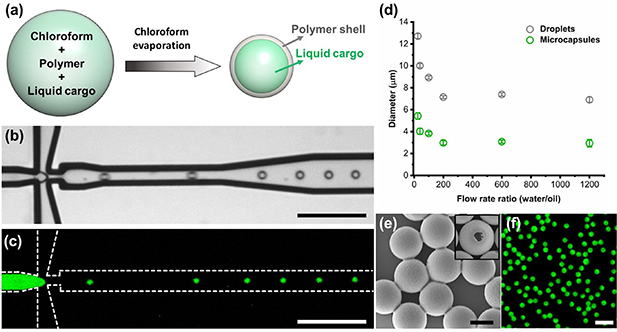
Figure 1. Microfluidic synthesis of microcapsules with liquid cargo. (a) Scheme of synthesis mechanism. (b) Bright-field and (c) fluorescence microscopy images of an oil-in-water emulsion generated by our flow-focusing microfluidic device. Scale bar is 100 μm. (d) Effect of flow rates on the size of generated droplets and corresponding microcapsules. (e) SEM images of microcapsules. The inset shows a broken microcapsule. Scale bar is 2 μm. (f) Fluorescence micrograph of microcapsules suspension. Scale bar is 10 μm.
Download figure:
Standard image High-resolution imageWe confirmed the formation of the core-shell structure and encapsulation of the liquid cargo using scanning electron microscopy (SEM) and fluorescence microscopy (figures 1(e) and (f)). Based on this microfluidic synthesis method, we have successfully obtained size-controlled, monodisperse microcapsules from different polymers (PMMA and PLLA) with different liquid cargoes (i.e. illustrated by green and red fluorescent dyes). The ability to precisely control the size and composition of these microcapsules provides a library of liquid compartments for the further fabrication of microswimmers.
We fabricated our microswimmers with liquid compartments through the sCAPA technique, as previously described [35]. To begin the fabrication, we first assembled silica microparticles (Ø = 4.5 μm) into the PDMS traps. An evaporating droplet of the silica suspension was moved over the PDMS substrate and silica particles were selectively placed inside the traps by the capillary forces (figures 2(a), (b) and video 2). Afterward, PMMA microcapsules (Ø = 3.1 μm, liquid core loaded with a green-fluorescent dye) were sequentially assembled next to silica microparticles (figures 2(c), (d) and video 3). To ensure that only one colloid was filled onto each PDMS trap during the deposition process, we carefully controlled the trap depth and surface tension of the colloid suspensions. We optimized the magnitude and direction of the capillary force relative to the particle position in the trap to achieve dumbbells containing one liquid compartment with yield greater than 80%. The fluorescent liquid was effectively retained even after assembly, thanks to the protective polymer shells (figures 2(e)–(g)). After successful sCAPA, the assembled structures were linked by thermal sintering at 90 °C for 15 min and harvested using an adhesive sacrificial layer of glucose-dextran as discussed in the Methods section. We also confirmed that the polymer microcapsules were still intact after transfer (SI, figures S3 and S4).
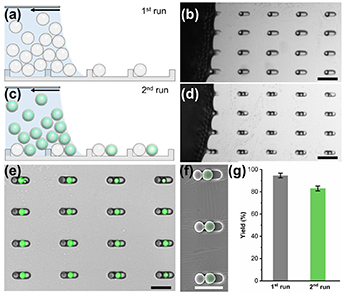
Figure 2. Fabrication of artificial microswimmers with liquid compartments using sCAPA. Scheme of the deposition of (a) the particles and (c) the microcapsules and corresponding microscopy images. The scale bars are 20 μm. (e) Merged bright-field and fluorescence micrographs and (f) the corresponding SEM image of dumbbell structures after sCAPA. The SEM image is false-colored to visualize the PMMA microcapsules. The scale bars are 10 μm. (g) Filling yield of each sCAPA step.
Download figure:
Standard image High-resolution imageAfter fabricating microswimmers in the shape of dumbbells, we utilized EHD flows to trigger their motion. This was achieved by exposing microswimmers to an AC electric field orthogonal to the electrodes. The propulsion mechanism is based on previously established models involving the polarization of a dielectric particle near the electrode ultimately leading to the generation of EHD flows. Specifically, EHD flows are radially symmetric around a single particle (figure 3(a)). And this symmetry can be broken by altering the particle's shape. The compositional asymmetry of the dumbbells implies that those flows are not symmetric around it, which in turn generates an unbalanced flow that propels the microswimmers along their long axis (figure 3(b)) [4, 10, 38]. The propulsion velocity of microswimmers (v) follows the equation:

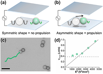
Figure 3. Active motion of microswimmers under an AC electric field. (a) Scheme of a single silica microparticle and a single PMMA microcapsule with symmetric EHD flows under an AC electric field. Grey and green arrows represent the and magnitude of EHD flows around the colloids. (b) Scheme of a microswimmer (silica microparticle + PMMA microcapsule) propelled by an AC electric field due to the breaking of symmetry in EHD flows, as represented by grey and green arrows. (c) Trajectory of one microswimmer under the AC electric field (Vpp = 8 V and f = 1.5 kHz). Scale bar = 10 μm (d) Plot of microswimmers' average velocity vmean as a function of the square of the electric field strength (Vpp/2H)2. The dashed line indicates the velocity corresponding to the mean Brownian displacements of similarly sized particles (0.38 μm s−1).
Download figure:
Standard image High-resolution imagewhere R is the radius of particles. And Ui is the fluid velocity given by
where β is a constant prefactor used as a single fitting parameter to obtain the experimental velocities,  0 is the solvent permittivity, κ−1 is the Debye length, Vp is the peak voltage, 2H is the separation between two electrodes, μ is the solvent viscosity, ω is the angular frequency, Ri is the particle radius, and r is the lateral distance from the particle center to the point where the EHD flow is evaluated. K' and K'' are the real and imaginary part of the polarization coefficient, respectively. Therefore, in a given microswimming system, the mean swimming velocity
  is proportional to the electric field strength E2 = (Vpp/2H)2 [4].
As shown in figure 3(c) and video 4, our dumbbells self-propel under the AC electric field (Vpp = 8 V, f = 1.5 kHz). Figure 3(d) in fact shows that the mean swimming velocity increases linearly with the square of the electric field strength, which is characteristic of propulsion from EHD flows.
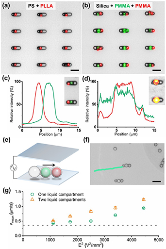
By combining microfluidic synthesis and sCAPA, we have thus demonstrated that the microswimmers with liquid compartments can be fabricated. To further demonstrate the capabilities of this approach, we fabricated a set of microswimmers with different materials and liquid compartments. We were first able to change the materials of the microswimmers to other polymers (PLLA and PS, figure 4(a)). Furthermore, we combined two different liquid compartments into a single microswimmer (figure 4(b)). The segregated liquid cargoes were well-protected within their respective compartments due to the polymer shells. We then showed that these cargoes (fluorescent dyes in hexadecane) could be released by permeabilizing the shells. Initially, the green and red fluorescent cores were separated (figure 4(c)). Next, by heating the polymer shells at 130 °C for 15 min, we triggered the microcapsules to merge and release their cargoes (figure 4(d)). Furthermore, the swimming velocity of the microswimmers with two liquid compartments increases linearly with the square of the electric field strength, showing similar characteristics to the dumbbells (figures 4(e), (f) and video 5). Compared with the microswimmers with one liquid compartment, the microswimmers with two liquid compartments showed a higher swimming velocity (figure 4(g)).
Figure 4. Microswimmers with multiple liquid compartments. (a) Merged bright-field and fluorescence micrograph of microswimmers with PS microparticle and PLLA microcapsule. (b) Microswimmers with one silica microparticle and two different PMMA microcapsules. Intensity profiles of green and red fluorescence of microswimmers along the assembly (c) before and (d) after the heating treatment (130 °C for 15 min). The insets show corresponding microswimmers. (e) Scheme of trimer microswimmers propelled under an AC electric field and (f) its trajectory under an AC electric field (Vpp = 8 V and f = 1.5 kHz). Scale bars are 10 μm. (g) Plot of average velocity vmean of microswimmers with one (green circles) and two (orange triangles) liquid compartments as a function of the square of the electric field strength (Vpp/2H)2. The dashed line indicates the velocity corresponding to the mean Brownian displacements of similarly sized particles (0.38 μm s−1).
Download figure:
Standard image High-resolution image
This model system presents a proof of concept to use microswimmers to transport and release cargo and trigger localized micro-reactions. The targeted delivery of reactants to specific locations and the ability to trigger reactions on demand could have future potential applications in fields such as drug delivery and environmental sensing, upon appropriate choice of materials and cargoes.
4. Conclusions
In summary, we present a modular platform that facilitates the precise fabrication of microswimmers with various liquid compartments. Our platform combines microfluidic synthesis and capillary assembly techniques, producing monodisperse microcapsules of controlled size and composition. The use of a flow-focusing microfluidic device enables the generation of a diverse library of liquid compartments for integration into microswimmers. Additionally, we demonstrate the ability of sCAPA to realize microswimmers with multiple liquid compartments and programmable functionalities. Incorporating multiple liquid compartments allows for simultaneous or programmable performance of multiple functions, enhancing the versatility of these microswimmers for various future applications. Our flexible modular assembly platform has the potential to enable the development of soft model systems for fundamental research and promote the use of microswimmers in diverse applications.
Acknowledgments
The authors thank Dr Yanming Xia, Professor Shenglin Ma, Dr Xiaobao Cao, and Professor Andrew deMello for the support with microfluidic device fabrication, Dr Steven van Kesteren and Carolina van Baalen for the help with sCAPA traps preparation as well as Python coding and image analysis. This project has received funding from the European Research Council (ERC) under the European Union's Horizon 2020 Research and innovation program Grant Agreement No. 101001514.
Data availability statement
All data that support the findings of this study are included within the article (and any supplementary files).
Author contributions
Author contributions are defined based on the CRediT (Contributor Roles Taxonomy) and listed alphabetically. Conceptualization: M H, L I; formal analysis: M H, L I, X S; funding acquisition: L I; investigation: M H, Z M, X S, D T; methodology: M H, L I, Z M, X S, D T; project administration: M H, L I; resources: M H, L I, X S; supervision: M H, L I; validation: M H, L I, X S; visualization: M H, L I, X S; writing—original draft: M H, L I; writing—review & editing: M H, L I, Z M, X S, D T.