

Abstract
As the development of wireless communication devices tends to be highly integrated, the miniaturization of very low frequency (VLF) antenna units has always been an unresolved issue. Here, a novel VLF mechanical communication antenna using magnetoelectric (ME) laminates with bending-mode structure is realized. ME laminates combines magnetostrictive Metglas amorphous ribbons and piezoelectric 0.7Pb(Mg1/3Nb2/3)O3–0.3PbTiO3 single crystal plates. From the simulation, we confirmed that the ME laminates can reduce the resonance peak from 18 kHz to 7.5 kHz by bending-mode structure. Experiment results show the resonance frequency can be farther reduced to 6.3 kHz by clamping one end of the ME antenna. The ME laminate exhibits a giant converse ME coefficient of 6 Oe cm V−1 at 6.3 kHz. The magnetic flux density generated by the ME antenna has been tested along with distance ranging from 0 to 60 cm and it is estimated that a 1 fT flux could be detected around 100 m with an excitation power of 10 mW.
Export citation and abstract BibTeX RIS
1. Introduction
Wireless communication tends to be miniaturized with the development of micro-nano technology [1, 2]. However, the miniaturization of low-frequency (LF) transmitting antennas has always been an unresolved issue as the integrated chip continuously improving. Due to the attenuation of electromagnetic (EM) waves underwater, the very low frequency (VLF, 3 kHz–30 kHz) electromagnetic waves can be able to applied to underwater communication [3–5]. The limitations of large size and high power consumption render traditional VLF wireless communication devices impractical for submarine underwater communication.
In order to obtain higher radiation efficiency, the size of the traditional antenna will reach hundreds or even thousands of meters. The power consumption will reach several thousand megawatts. In this case, demand for small-size, light-weight, low-power consumption, and low-cost VLF transmitting antenna has emerged [4–9]. Recently, ME transmitting antennas combining acoustic resonance and magnetoelectric effect (ME effect) have attracted widespread attention and have been proven to be a new way to break the limitations of traditional VLF antenna [10–13]. The ME effect refers to an electrical polarization under the presence of magnetic field, or magnetization change with the application of an external electric field, making ME laminates a promising candidate material for realizing various devices [14–21]. In contrast to traditional VLF antennas, ME antennas show advantages of high sensitivity, low cost, miniaturization and low power consumption in application potential of wireless communication devices [1, 2, 22, 23].
The structure of the ME antennas based on bulk acoustic wave mediation was first proposed by Yao in 2015 [24]. ME effects can be divided into direct ME coupling and converse ME coupling [9]. ME transmitting antennas that depending on converse ME coupling effect provides a huge possibility for miniaturization of VLF antennas in wireless communication systems such as the Internet of Things, wearable monitoring systems, biological communications technology, and most importantly a feasible solution for underwater communication [25–27].
In 2017, Liang et al first verified the feasibility of ME mechanical antenna by experiment, but it was a very high frequency antenna [8]. Xu et al prepared ME transmitting antennas based on Metglas and PZT(Pb(ZrxTi1-xO3). The resonant frequencies of the devices are 28 kHz, but the working frequency is still too high and hard to tune [6, 9].
In order to realize the tunability of the working frequency of the ME laminates, the change of the material size gradient, the DC bias magnetic field, and loads are used as adjustable parameters [28–34]. Gao et al prepared a tunable bending-mode structure of ME materials [35]. Such asymmetric structure of ME laminates can realize the effective reduction and tunability of the resonance frequency. Although there are plenty adjustment methods for the resonant frequency [36–42], it is expected that the working frequency reduction and tunability of the ME transmitting antennas can be realized by applying a mechanical load to the bending mode of the ME material.
In our work, a VLF antenna based on clamped bending-mode structure ME laminates was designed and fabricated. The ME antenna consists of six length-magnetized Metglas alloy and one thickness-polarized 0.7Pb(Mg1/3Nb2/3)O3–0.3PbTiO3 single crystal (PMN–PT), as shown in figures 1(a) and (b). We conducted simulation on the vibration modes of ME materials. The experimental results matched well with the simulation. The resonant frequency of the ME laminate was successfully be reduced to 6.3 kHz by mechanical clamping. The magnetic flux density generated by the ME antenna has been tested along with distance ranging from 0 to 60 cm. It was predicted that 1 fT flux could be detected around 100 m with an excitation power of 10 mW.
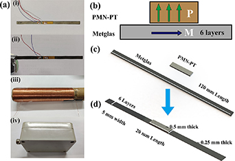
Figure 1. (a) Physical photography of the device. (i) ME transmitting antenna, (ii) clamped ME laminates, (iii) the near-field receiving coil, (iv) the far-field receiving detector. (b) A schematic diagram of the principle of ME laminates. (c) A schematic of magnetoelectric laminates' size and compound method. (d) Side view of the schematic and fabricated ME antenna.
Download figure:
Standard image High-resolution image2. Design and fabrication
2.1. Design and operation
A VLF ME mechanical transmitting antenna consisting of magnetostrictive Metglas 2605 amorphous ribbons and piezoelectric PMN–PT single crystal plates has been proposed, as shown in figure 1(a-i). As shown in figure 1(b), the piezoelectric phase deformed due to the converse piezoelectric effect and conducted the deformation to the magnetostrictive layer under the external electric field. Then the magnetostrictive phase induces magnetic flux, and the ME antenna can be fabricated based on converse ME effect.
For strip-shaped ME laminates, the electromechanical resonance (EMR) frequency of the length vibration mode is generally higher to about 30 kHz. For ME laminates with asymmetric structure, there is a resonant peak, which is much lower than the resonant peak of the length mode. The vibration mode has been changed from a simple length vibration mode to a complex vibration mode. The drop in working frequency is mainly contributed by the bending vibration modes. It is a generalized bending vibration mode of a pure cantilever beam. In order to enhance the value of the resonant peak, we clamped one single end of the ME laminates to form a cantilever beam structure as shown in figure 1(a-ii).
Solenoid coils were used to measure the near-field radiation ability of the ME transmitting antenna, as shown in figure 1(a-iii), and another magnetic detector was used as the receiver to measure the far-field radiation ability of the ME transmitting antenna, as shown in figure 1(a-iv). The optimal direct current (DC) bias magnetic intensity was provided by Hall coil in order to maximize the converse ME coefficient of the ME transmitting antenna.
2.2. Fabrication
The ME transmitting antenna shown in figure 1(b) (size of 120 mm × 5 mm × 0.75 mm) constituted by Metglas/PMN–PT bilayer. Six Metglas ribbons (of dimension 120 mm × 5 mm × 0.25 mm) were bonded together to be the magnetostrictive phase by epoxy resin (West system 105/206). Then, a piece of PMN–PT single crystal plate (20 mm × 5 mm × 0.5 mm) was bonded to the middle of the upper surface of the magnetostrictive phase as shown in figure 1(c). The laminate was treated at 50 °C under certain pressure for 6 h in order to obtain a higher ME coupling. The PMN–PT layer was polarized along the thickness direction and the Metglas layer was magnetized along the length direction. Polarization and magnetized are necessary in order to induce the desired piezoelectric effect and magnetostrictive effect in the PMN–PT layer and Metglas ribbons. Figure 1(a-iii) shows a near-field receiver which made up of copper coil with a diameter of 30 mm, a length of 120 mm and three hundred turns to measure the near-field radiation of the ME transmitting antenna. Figure 1(a-iv) shows a magnetic detector based on ME laminates to measure the far-field radiation of the ME transmitting antenna.
3. Measurement and results
3.1. Simulation
First of all, COMSOL Multiphysics software was used to find a structure which can reduce the resonance frequency of the ME transmitting antenna. The vibration mode of the ME transmitting antenna was studied by using the finite element method.
Based on previous research, the finite element simulation of the magnetic flux density and strain of ME materials was carried out. We modeled and simulated the unclamped and clamped ME transmitting antennas, respectively. The ME sample model was constructed, and a DC magnetic field and an alternating (AC) magnetic field were applied along the longitudinal axis. As shown in figure 2(a), for no-clamped ME laminates, the boundary conditions of solid mechanics were set as free. It clearly indicates that the magnetic flux density and strain exhibit maximum value at the center of the piezomagnetic. As shown in figure 2(b), for the ME antenna sample clamped on one side, the solid mechanical boundary condition on the side was set to be fixed, and obviously its magnetic flux density distribution is different from that of a no-clamped ME transmitting antenna. Figures 2(c) and (d) show the modal analysis of the no-clamped and clamped ME transmitting antenna, respectively. It is observed that the ME transmitting antenna without clamping had a single vibration mode, which referred to a length vibration mode at the resonance frequency of 17.5 kHz; while the vibration mode of the ME antenna single-sided clamped was more complicated, and it mainly included the lower frequency in bending vibration mode and a higher resonant frequency in length vibration mode. It can be predicted that the resonant frequency can be effectively reduced by clamping the unilateral side of the asymmetric geomagnetic ME transmitting antenna. In the following section, sample preparation and performance testing will be carried out.

Figure 2. The finite element simulation of magnetic flux density by COMSOL multiphysics software of (a) no-clamped ME laminates and (b) clamped ME laminates. Vibration modes of (c) no-clamped and (d) clamped ME laminates.
Download figure:
Standard image High-resolution image3.2. Characterization of ME laminates
After the fabrication of the ME antennas, we characterized the properties of ME transmitting antennas. As shown in figure 3(a), the impedance and phase degree of the no-clamped ME antenna have been measured through impedance analyzer. For the ME transmitting antenna not clamped, there is a EMR frequency of 17.5 kHz. For the ME transmitting antenna of the clamped state, two resonance frequency can be clearly observed, respectively at 6.3 kHz and 22 kHz as shown in figure 3(c).
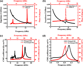
Figure 3. (a) Impedance of the no-clamped ME antenna at resonant frequency. (b) Impedance of the no-clamped ME antenna at resonant frequency. (c) Converse ME coefficients at resonant frequency of the clamped and no-clamped ME antennas. (d) An enlarged diagram of converse ME coefficient.
Download figure:
Standard image High-resolution imageWe used the solenoid coil (shown in figure 1(a)) wrapping the ME transmitting antenna to measure the near- field converse ME coefficient, as shown in figure 3(c). A signal analyzer was used to detect the electromotive force of the solenoid coil. From the electromagnetic coefficient of the solenoid coil, the radiated magnetic flux of the ME antenna can be calculated. Then the converse ME coefficients at the resonance frequency have been characterized. As shown in figure 3(d), the ME transmitting antenna in the clamped state exhibits a converse ME coefficient of 6 Oe cm V−1 and shows an obvious resonant frequency at 6.3 kHz, which is nearly four times lower than the 25 kHz (made by Dong et al) [9] and the 24 kHz (made by the team of Virginia Tech) [6]. We used a more advanced PMN–PT as the piezoelectric phase (with higher piezoelectric properties than PZT), such a high converse ME coefficient is more than twice that of the samples made by the Northeastern University team [9]. The experimental results agree well with the simulation predictions.
We tested the optimal DC bias magnetic field of the ME transmitting antenna, which directly had impact on the performance of radiation ability, as can be seen in figure 4. We placed the ME laminate in the Hall coil, change the DC current of the Hall coil, and measure the maximum value of the CME coefficient at the resonant frequency, so as to measure the optimal DC bias magnetic field of the ME material. The responsivity of the ME laminates at the resonance frequency is affected by the magnitude of the bias magnetic field (HDC). The resonance frequencies show slight dispersion with the biased DC magnetic field changing varies in the range of 0–10 Oe to the no-clamped ME antenna and the optimal HDC is about 5 Oe, as shown in figure 4(a). Figure 4(b) reveals the resonant state converse ME coefficients of the ME antenna under different HDC, where the optimal HDC is about 3 Oe. More importantly, the converse ME coefficients of the clamped Metglas/PMN–PT laminates can reach as high as 6 V cm Oe−1 at a much lower resonant frequency of ∼6.2 kHz, which guarantee the antenna sufficient radiation capacity. Different to the non-clamped ME transmitting antenna, the resonance frequencies show almost imperceptible dispersion with the biased DC magnetic field changing varies in the range of 0–9 Oe.

Figure 4. (a) The resonance frequencies of no-clamped ME antenna show slight dispersion with the biased DC magnetic field changing varies in the range of 0–10 Oe. (b) The resonant state converse ME coefficients of the no-clamped ME antennas under different magnetic field bias HDC. (c) The resonance frequency of clamped ME antenna approximately fixed at the same frequency with the biased DC magnetic field changing varies in the range of 0–9 Oe. (d) The resonant state converse ME coefficients of the clamped ME antennas under different magnetic field bias HDC.
Download figure:
Standard image High-resolution image4. Application and test
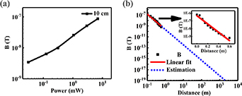
Then we tested the far-field radiation performance of the ME transmitting antenna of clamped state. A high-resolution magnetic detector, which has a wider frequency domain and can respond to the far-field magnetic flux density, is used as the far-field detector. Figure 5(a) shows the magnetic flux density (at the distance of 5 cm from the ME transmitting, which means that the detector is close to the one side of the antenna) detected by the magnetic sensor as a function of the input power to the ME transmitting antenna in clamped state. Due to the capacitance characteristics of the ME heterojunction, there is a phase difference between its voltage and current. We test the voltage and current with oscilloscope, calculate the phase angle. Finally we calculate the power of the ME antenna.
Figure 5. (a) The magnetic flux density detected by the ME receiver as a function of the increasing input power to the clamped ME antenna at the frequency of 6.3 kHz. (b) The solid line and the inserted figure are the magnetic flux density detected by the ME receiver as a function of the distance to the clamped ME antenna at the frequency of 6.3 kHz. The dotted line is the estimation of far-field radiation capability.
Download figure:
Standard image High-resolution image
We also measured the magnetic flux density generated by the ME transmitting antenna as a function of the distance with the power of 10 mV. In figure 5(b), under the atmospheric environment, the magnetic flux density radiated by the ME transmitting antenna in clamped state decreased as the distance increases. At the distance of 0.5 m, our ME transmitting antenna can still radiate a magnetic flux density of 1.12 nT at the excitation power of 10 mW. The ME mechanical transmitting antenna based on the converse ME effect has a good application prospect. After extrapolating the fitting curve, it can be estimated that a 1 fT flux could be detected around 100 m at the power of 10 mW. Even though the input power is only 10 mW, we nearly achieved the same far-field transmission capability as the ME antenna made by Virginia Tech, whose input power is as high as 500 mW. At the same test distance, the radiated magnetic flux density per unit power of our ME antenna is higher than the sample by Virginia Tech.
5. Conclusion
In summary, based on the converse ME effect, a novel VLF mechanical transmitting antenna was realized. The ME laminates with bending-mode structure combined magnetostrictive Metglas 2605 amorphous ribbons and piezoelectric PMN–PT single crystal plates.
By the finite element simulation results, we confirmed that the ME laminates in bending-mode structure can reduce the resonance peak from 18 kHz to 7.5 kHz. Experiments show that the resonance frequency can be reduced to 6.3 kHz by clamping one end of the ME antenna. Meanwhile, the clamped ME laminate exhibits a giant converse ME coefficient of 6 Oe cm V−1. We reduced the working frequency of the ME antenna to around 6 kHz. It will not only makes the electromagnetic wave attenuate lower in the underwater communication range of a certain distance, but also maintains a good data transmission speed.
Furthermore, the capability of the ME transmitting antenna for near-field and far-field was tested. Owing to the extraordinary properties like real-time, highly responsive, excellent linearity, low cost and so on, the ME transmitting antenna holds great potential for wireless communication.
Acknowledgments
This work was supported by the National Key R&D Program of China (No. 2021YFA0716500), Shanghai Science and Technology Innovation Action Plan Program (No. 20511107404), Shanghai Pujiang Program (Nos. 2019PJD012 and 19PJ1402900) and Opening Project of State Key Laboratory of High Performance Ceramics and Superfine Microstructure (No. SKL202012SIC).
Data availability statement
The data that support the findings of this study are available upon reasonable request from the authors.