
Abstract
We present a fully charge self-consistent implementation of dynamical mean field theory (DMFT) combined with density functional theory (DFT) for electronic structure calculations of materials with strong electronic correlations. The implementation uses the Quantum ESPRESSO package for the DFT calculations, the Wannier90 code for the up-/down-folding and the TRIQS software package for setting up and solving the DMFT equations. All components are available under open source licenses, are MPI-parallelized, fully integrated in the respective packages, and use an hdf5 archive interface to eliminate file parsing. We show benchmarks for three different systems that demonstrate excellent agreement with existing DFT + DMFT implementations in other ab initio electronic structure codes.
Export citation and abstract BibTeX RIS

Original content from this work may be used under the terms of the Creative Commons Attribution 4.0 licence. Any further distribution of this work must maintain attribution to the author(s) and the title of the work, journal citation and DOI.
1. Introduction
Dynamical mean field theory (DMFT) is a conceptualframework and a computational method to deal with strong correlations between interacting quantum particles. It can be combined with electronic structure methods, such as density functional theory (DFT) or the GW method in order to compute and predict the properties of materials with strong electronic correlations (for reviews, see [1–3]). DMFT is the poster child of quantum embedding methods. Central to these approaches is the definition of a subset  of the total Hilbert space, which is spanned by a set of appropriately chosen local orbitals. A high-level method (here, DMFT) is used for treating many-body effects in the correlated subspace, while the rest of the Hilbert space is treated with a simpler method, such as approximations to DFT or perturbation theory [1–3]. Any quantity in the full Hilbert space can be projected onto the correlated subspace. When applied to the full Green's function, this defines a local projected Green's function which is the key observable on which DMFT focuses. Correspondingly, the result of the many-body calculation in
  can be embedded in the full Hilbert space by 'upfolding'.
Two types of approaches have been implemented for constructing the DMFT equations, which are colloquially referred to by the community as 'Wannier'- or 'projector'-based methods.
In the former case, a code like Wannier90 (W90) [4] is typically used to formulate a donwfolded Hamiltonian. In the simplest case this Hamiltonian is even directly formulated in the correlated subspace itself, corresponding to 'maximal downfolding'—in which case this is the only space considered in the calculation. In practice, this is what is generally meant by performing DFT + DMFT calculations using 'Wannier-'orbitals, and it is often the modus operandi when using W90. This approach is closer in spirit to model calculations but does not take full advantage of the broader DFT + DMFT framework.
In more general implementations, the projection/downfolding and embedding/upfolding procedures are performed by defining projectors from the total Hilbert space to the correlated subspace, which involve the overlaps between the local orbitals spanning  and the basis functions spanning the full space. These implementations are colloquially referred to as 'projector-based' and are closer in spirit to what is done in '+U' extensions of DFT (which, incidentally, correspond to solving the DMFT embedded problem with a static mean-field approximation). It should be noted that, once constructed, the projectors onto
  also yield a set of Wannier functions (WFs) spanning this subspace, but the user typically does not have direct access to these WFs in order to look at dispersions or real-space density as is readily available using W90. While historically the naming convention of 'Wannier'- versus 'projector'-based approach appears reasonable, the implementation presented here requires an update of this terminology.
In this article, we present a 'projector-based Wannier' implementation in which the DFT + DMFT framework is implemented in its general form in a larger Hilbert space (e.g. using a basis set of Kohn–Sham Bloch wavefunctions), while using projector functions computed from W90 instead of internally in the DFT code.
Besides the obvious advantage of benefiting from the flexibility and ongoing developments of W90, our implementation also allows to implement full charge self-consistency, which is typically not done when using a maximally downfolded Wannier Hamiltonian. Indeed, the DFT + DMFT construction relies on a (free-) energy functional which depends both on the local charge density in the full Hilbert space and on the projected frequency-dependent local Green's function in  . Extremalizing this energy functional requires to reach a self-consistent solution for both of these observables. Hence, the local charge density is modified by the many-body contributions as compared to a pure DFT calculation. This is physically important, especially for those materials in which electrons reside in very localized orbitals. The simplest approximations to DFT such as LDA incorrectly describe these states as itinerant, hence yielding an incorrect charge density and typically a too small value of the equilibrium unit cell volume.
In practice however, many electronic structure calculations with DMFT report results in which the self-consistency over the charge density has not been enforced. In such calculations, usually called one-shot (OS) in the jargon of the field, DMFT is only used as a post-processing tool to include many-body effects on top of a converged DFT calculation. Several codes however are available which combine DFT and DMFT in order to achieve charge self-consistency, such as implementations based on the Wien2k, VASP, Elk, ABINIT, CASTEP and other electronic structure codes [5–13]. All these implementations use projectors constructed internally, rather than Wannier orbitals constructed using W90.
Up to now relatively few systematic studies on the importance of charge self-consistency are available [6, 14–18]. While some reports identified systems in which charge self-consistency may be neglected and others in which it plays a crucial role [15, 16], little is known about general trends. This question is likely to be especially relevant in the context of heterostructures of correlated materials in which charge ordering or interfacial charge transfer take place. Thus, with rapidly progressing method developments and rising computational power which allow to treat such problems with multiple correlated atoms within DMFT, charge self-consistency becomes an increasingly important question.
Here, we present an implementation of a fully open-source charge self-consistent (CSC) DFT + DMFT computational framework. It uses the Quantum ESPRESSO (QE) package [19] for the DFT calculations, the W90 code [4] for the generation of the up-/down-folding matrices, and the TRIQS/DFTTools software package [5, 20] for all the DMFT-related routines of up-/down-folding and handling of Green's functions. All parts of the processes are MPI-parallelized and are thus suited for larger systems and denser k-point meshes. The modifications are fully integrated within the software packages QE (v.7.0) and TRIQS/DFTTools (v.3.1). A seamless wrapper routine to manage the workflow between QE, W90 and TRIQS is available in the solid_dmft package [21], which enables the user to run fully CSC calculations based on a single input file.
The paper is structured as follows: in section 2 we introduce the theoretical framework that is the basis of the implementation. The workflow describing the usage of the different codes to run CSC calculations is outlined in section 3. Finally, we discuss benchmarks in section 4 before concluding in section 5.
2. Theoretical framework
The central quantity in DFT + DMFT calculations is the one-electron lattice Green's function,

i.e. a function of both the quasi-momentum k and of frequency ω, or imaginary Matsubara frequency iωn
as used in the following. Here, ν runs over bands of a (Kohn–Sham) Hamiltonian diagonal in momentum space, i.e. formulated in terms of Bloch states |ϕν
k
⟩ with corresponding eigenvalues  ν
k
. We introduce projectors on these states as
ν
k
. We introduce projectors on these states as

from which it follows that the Bloch Hamiltonian can be written as  . The chemical potential in equation (1) is given by μ, and the corrections to the single-particle eigenenergies are represented in terms of the self-energy matrix denoted by
  (defined later). At the initial step of the DFT + DMFT iteration, this term may be set to zero.
Central to the DMFT framework is the definition of a subspace of the total Hilbert space within which strong electronic correlations are taken into account. This subspace is denoted by  , defined more precisely in section 2.1.1, and is spanned by a set of local orbitals indexed by m. We need to define appropriate transformations to perform the transition between the full Hilbert space and the correlated subspace. This can be achieved by introducing projector functions Pmν
(k), which carry out the down-folding, i.e. the transformation from the delocalized band-space to the localized orbital-space with indices ν and m, respectively. The key assumption made in DMFT is that the self-energy can be approximated as a spatially local (momentum-independent) matrix when considered in the basis of local orbitals. Hence, the self-energy matrix in the full Hilbert space is obtained as:
, defined more precisely in section 2.1.1, and is spanned by a set of local orbitals indexed by m. We need to define appropriate transformations to perform the transition between the full Hilbert space and the correlated subspace. This can be achieved by introducing projector functions Pmν
(k), which carry out the down-folding, i.e. the transformation from the delocalized band-space to the localized orbital-space with indices ν and m, respectively. The key assumption made in DMFT is that the self-energy can be approximated as a spatially local (momentum-independent) matrix when considered in the basis of local orbitals. Hence, the self-energy matrix in the full Hilbert space is obtained as:

in which  is the difference between the impurity self-energy and the double counting (DC) correction, i.e.
  . Note that in this expression, the projector functions Pmν
(k) are used to upfold the self-energy in the correlated subspace to the full Hilbert space.
. Note that in this expression, the projector functions Pmν
(k) are used to upfold the self-energy in the correlated subspace to the full Hilbert space.
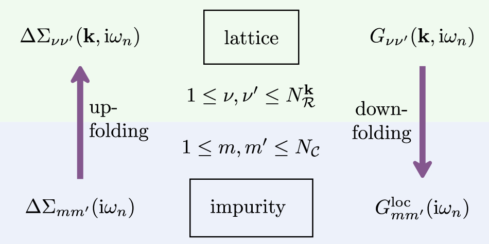
The local self-energy ΔΣmm'(iωn
) is calculated within DMFT by solving a 'quantum impurity problem' corresponding to a self-consistent embedding of the correlated atomic shell associated with  [22]. This quantum impurity problem is defined by (i) a local Hamiltonian of many-body interactions and (ii) a frequency-dependent dynamical mean-field (or Weiss field) which specifies the coupling between the embedded atomic shell and the self-consistent bath. The dynamical mean-field is determined iteratively, and in order to update its value from one iteration to the next, one needs to project the full Green's function (1) onto the local correlated subspace. This downfolding procedure is achieved by using the projectors and by performing a momentum-summation according to:

The Weiss field  is then obtained from the Dyson equation
  . In this article, we do not describe the algorithms that are available to solve the impurity problem and refer the reader to extensive reviews of appropriate methods for details [23].
Figure 1 summarizes schematically the upfolding and downfolding procedures between the full Hilbert space and the subspace of correlated states.

Figure 1. Schematic of up- and down-folding between impurity and lattice space.
Download figure:
Standard image High-resolution image2.1. Up-/down-folding
2.1.1. Hilbert spaces
In this section, we specify more precisely the different Hilbert spaces considered in this paper and in our implementation. We define four different Hilbert spaces, continually reducing the number of bands/orbitals until we obtain the correlated subspace  that we aim to treat within DMFT. As starting point we choose a general Kohn–Sham (KS) Hamiltonian of a non-magnetic DFT calculation. Note that depending on the specifics of the system, some or all Hilbert spaces may be the same.
We start from the full Bloch space  associated with the complete basis of KS states |ϕν
k
⟩ of dimension
associated with the complete basis of KS states |ϕν
k
⟩ of dimension  dim
dim . While in theory this could contain infinitely many bands, in practice, it is clear that this space only serves as a hypothetical construct, since the number of KS states is finite in any DFT calculation. Yet, a large fraction of KS states is described reasonably well within DFT, so it is unnecessary to define WFs for such states, e.g. semicore or other states far away from the Fermi level. More important is, thus, the reduced KS space
  , i.e. a subspace of KS states limited either via band indices or an energy window ('outer window' in Wannier90). We define its dimension as
  dim
dim , which may carry a k-dependence in case of entanglement (see figure 2). For this reason, it is evident that such a basis does not constitute a suitable starting point for the definition of a tight-binding (TB) Hamiltonian. However, one may construct such a TB Hamiltonian via an optimization/orthonormalization of the Hilbert space, implemented in Wannier90, details of which can be found in the appropriate literature [24]. This allows to define a Hilbert space
  , containing
  dim
dim optimized and orthonormalized Bloch states
  with band indices μ, μ'. A straight-forward gauge transformation to orbital space then defines WFs |wα
k
⟩ with orbital indices α, α', see section 2.1.2. Finally, one may select a subset of m WFs from this complete basis as the 'correlated subspace'
with band indices μ, μ'. A straight-forward gauge transformation to orbital space then defines WFs |wα
k
⟩ with orbital indices α, α', see section 2.1.2. Finally, one may select a subset of m WFs from this complete basis as the 'correlated subspace'  , i.e.
  dim
dim .
.

Figure 2. Exemplary definitions of Hilbert spaces described in section 2.1.2 (c)  of a k-dependent outer window
  and the optimized and orthonormalized derived Hilbert space
  . Bands in
  and
and  are shown in blue and red, respectively. We use the cubic perovskite SrVO3 in a
  supercell with projections onto an atomic d-shell for demonstration purposes.
Download figure:
Standard image High-resolution imageIt now becomes clear that, generally speaking, the up- and down-folding occurs between the Hilbert spaces  and
and  . Therefore, the main task of the following manuscript is to find the correct projector functions
  that allow up- and down-folding between the orbital space
  (and more generally
  ) and the space
  of Bloch states, illustrated in figure 1. In the following the terms and notations referring to the original Bloch states denote the respective objects in
  and are labelled with index ν. Equivalently, objects in
  will be labelled by μ if considered in the diagonal band gauge, and α if formulated in the orbital gauge, where
  . Finally, correlated orbitals with index m belong to
  . Each correlated orbital m is associated with an atomic site i, meaning that the orbital space
  can be spanned by multiple sites. Note that in general the construction of projector functions Pαν
(k) for
can be spanned by multiple sites. Note that in general the construction of projector functions Pαν
(k) for  is not strictly necessary as it is used only for post-processing purposes, but not in the DMFT equations.
2.1.2. Projector functions
In the following, we consider three cases that capture the different scenarios for (hypothetical and) usual applications.
- (a)Case 1—infinite set of bands:
 First, we construct a set of WFs from the entire set of KS states. While the case of an infinite set of bands is clearly hypothetical, we use this paragraph to introduce the basic quantities and concepts. The WFs |wα
k
⟩ are obtained simply via change of basis aswhere we introduced unitary matrices which define the gauge. The WFs may alternatively be expressed in real space as centered at lattice site Ri
via a Fourier transform (FT), i.e.Since, due to the gauge freedom, the are not uniquely defined, different definitions of WFs can be found in the literature. While here we use the spread minimization as implemented in W90, an alternative is given in the typical 'projector'-type approach by using code-internal routines to determine the gauge. The advantage of maximally localized Wannier functions (MLWFs) in W90 thus lies not only in obtaining a unique solution with ideal localization properties, but also in the flexibility given by a DFT-code-independent approach. Note that the following formalism is general, i.e. remains valid for other definitions of the gauge freedom. The spread Ω can be calculated from the WFs at the respective lattice sites in the unit cell (Ri
= 0) as:This can further be divided into a gauge invariant term ΩI and a gauge dependent term. The latter is used in the Marzari–Vanderbilt (MV) method [25] to obtain MLWFs.The projector functions introduced in equation (4) can be readily identified as the unitary matrix, i.e. the transformation from the Bloch to orbital gauge:For the initial guess of the projector function so-called trial localized orbitals |gα ⟩ are used in Wannier90, e.g. atomic-like states. The initial overlap to the KS states is defined asNote that unless the trial localized orbitals |gα ⟩ are fully contained within (i.e. if ), the projector functions need to orthonormalized (see the following paragraph, i.e. case 2). During the spread minimization the are then optimized to yield the resulting MLWF.
First, we construct a set of WFs from the entire set of KS states. While the case of an infinite set of bands is clearly hypothetical, we use this paragraph to introduce the basic quantities and concepts. The WFs |wα
k
⟩ are obtained simply via change of basis aswhere we introduced unitary matrices which define the gauge. The WFs may alternatively be expressed in real space as centered at lattice site Ri
via a Fourier transform (FT), i.e.Since, due to the gauge freedom, the are not uniquely defined, different definitions of WFs can be found in the literature. While here we use the spread minimization as implemented in W90, an alternative is given in the typical 'projector'-type approach by using code-internal routines to determine the gauge. The advantage of maximally localized Wannier functions (MLWFs) in W90 thus lies not only in obtaining a unique solution with ideal localization properties, but also in the flexibility given by a DFT-code-independent approach. Note that the following formalism is general, i.e. remains valid for other definitions of the gauge freedom. The spread Ω can be calculated from the WFs at the respective lattice sites in the unit cell (Ri
= 0) as:This can further be divided into a gauge invariant term ΩI and a gauge dependent term. The latter is used in the Marzari–Vanderbilt (MV) method [25] to obtain MLWFs.The projector functions introduced in equation (4) can be readily identified as the unitary matrix, i.e. the transformation from the Bloch to orbital gauge:For the initial guess of the projector function so-called trial localized orbitals |gα ⟩ are used in Wannier90, e.g. atomic-like states. The initial overlap to the KS states is defined asNote that unless the trial localized orbitals |gα ⟩ are fully contained within (i.e. if ), the projector functions need to orthonormalized (see the following paragraph, i.e. case 2). During the spread minimization the are then optimized to yield the resulting MLWF. - (b)Case 2—isolated set of bands:.We now assume that only a subset of the total number of KS states contributes to the construction of the Wannier basis. We further assume that it constitutes an isolated set of states, meaning that is k-independent. In particular this means that no KS states |ϕν
k
⟩ from outside this window cross target bands at any k. In this case, trivially divides into two orthogonal subspaces, , where each KS Bloch function is either fully contained in or in , so that |ϕν
k
⟩ with form a complete and orthogonal basis in . However, if the projectors are initialized as in equation (9), they need to be orthonormalized, since in general the trial localized orbitals |gα
⟩ are not fully contained in . Thus, we first define non-orthogonal from the KS states within (in this paragraph we will omit the superscript k in , since we assume an isolated set of bands), i.e.To orthogonalize we calculate the overlap asand, for a simplified notation we further define. Following this, the orthonormal set of WFs is given aswithThe final orthonormal (and potentially spread-minimized) set of unitary projector functions is then given as as above.Finally, we note that in this specific case of an isolated set of bands it is possible to use the set of Wannier states in as a basis set during the DMFT cycle instead of using the KS states (in the following paragraph we use superscripts TB and KS for clarity). The advantage of the Wannier basis is that it has a more direct physical interpretation in terms of atomic orbitals. This is possible because the same set of bands is included in the chosen window at all k-points, so that the one-particle KS Hamiltonian can be unitarily rotated to this TB basis:The 'effective projector functions' used in the code can be expressed in this basis and simply become. The upfolding of the self-energy (equation (3)) becomes trivial in this basis: it simply amounts to constructing the self-energy as a matrix with a block equal to if and 0 otherwise. The lattice Green's function in the Wannier (TB) basis and projected Green's function in simply read:and the DMFT self-consistency loop is implemented as usual as. For practical purposes we define here the diagonalized Wannier Hamiltonianwhich is identical to only in the case of an isolated set of bands.We will use the term 'Wannier mode' when the DMFT equations are implemented in this manner using the Wannier basis, while the term 'Band mode' is used to designate the more general implementation in the basis of KS Bloch states. Our implementation allows the user to choose one mode or the other. We emphasize however that the 'Wannier mode' is only correct for an isolated set of bands and should be used only in this case, i.e. if the projector functions Pαν
(k) are unitary (square) matrices, as outlined in appendix
B . The use of WFs constructed with W90 to define the projectors, while implementing the DMFT cycle in a general manner in the KS basis is one of the novel aspects of our implementation. - (c)Case 3—entangled bands:.Finally, one may construct WFs from a set of bands that is not isolated, i.e. it contains KS states that are undesired in the construction of the WFs. This means that within a specified energy window ('outer window') and/or within a specified range of band indices in it may contain a (k-dependent) number of additional KS states, illustrated in figure 2. The additional states are typically of a different orbital character and thus undesirable when selecting the correlated subspace, but can be excluded via a disentanglement procedure. To this end we first define disentanglement matrices , which are generally not square but rectangular matrices of dimension , used to optimize the cell-periodic part of the KS states within :This can be achieved by minimizing the gauge invariant term of the spread, ΩI, which ensures k-point connectivity, or 'global smoothness of connection' in the optimized states [26]. This leaves us with optimized KS states , which can further be spread-minimized as outlined in the previous paragraph:Following this, the projector functions used for the up-/down-folding are then given by


Note that in this case the projector functions may be rectangular (since  ), i.e. need not necessarily be unitary (i.e. satisfy
  ). This means that the down-folding in equation (4) from Bloch to Wannier basis is not invertible, that is the reverse process of up-folding does not recover the full TB Hamiltonian and lattice Green's function. In these cases a formulation of the DMFT equations in an orbital basis as outlined in the previous paragraph (case 2) and in the appendix
We close the discussion of the different subspaces by remarking that the case 2 leads to projector functions  , which are very similar to those obtained in the typical 'projector'-based approach for an isolated set of bands [16]. In contrast, for cases 1 and 3 discussed the projector functions may differ more drastically due to the absence of a disentanglement procedure to match the underlying DFT band structure in the typical 'projector'-based approach. In other words, the projector functions described here result not only from a raw projection on atomic orbitals, but also incorporate some of the complexity of orbitals in a real solid by respecting the underlying band structure such as ligand bonds, while at the same time optimizing the localization condition.
2.2. Charge self-consistency and total energy
This section provides the most important equations required for CSC calculations, closely following references [27, 28].
The interacting charge density at inverse temperature β is given by

Here, the KS charge density is defined as

with the KS occupation numbers  and the KS Fermi level μKS chosen such that the correct total charge is obtained within the DFT calculation. Note that for each iteration ρKS(r) represents the non-interacting contribution to the physical charge density ρ(r), and thus is not identical to the true DFT ground state density
  (only in the first iteration). In order to obtain the correction to the non-interacting charge density one needs to calculate the corrected occupations by subtracting the non-interacting part as follows:

where  is the difference in chemical potentials. The second line in the equation above is derived using the definition
  and
and ![$\hat{G}-{\hat{G}}_{\mathrm{K}\mathrm{S}}={\hat{G}}_{\mathrm{K}\mathrm{S}}[{\hat{G}}_{\mathrm{K}\mathrm{S}}^{-1}-{\hat{G}}^{-1}]\hat{G}$](https://content.cld.iop.org/journals/0953-8984/34/23/235601/revision3/cmac5d1cieqn95.gif) . Note that this expression is better behaved computationally, since the right-hand side decays faster with frequency than the slow decay
. Note that this expression is better behaved computationally, since the right-hand side decays faster with frequency than the slow decay  of individual Green's functions. We now define the correction to the ground state charge density as

where the charge density correction  is defined as

with the matrix elements given by

Note that in order to maintain charge neutrality the trace over the occupation corrections must amount to zero, i.e. the changes in the occupations do not change the total charge:

With these definitions the total interacting charge density in equation (20) can be recast into

For practical purposes, it is advisable to absorb the non-diagonal elements by orthonormalizing the KS states via a unitary transformation  [6], obtained as

where  is diagonal and contains the orthonormalized occupation updates. After embedding
  and
and  as block-matrixes into identity matrices in
  we obtain updated KS states as

Finally, the charge density is given as

where the renormalized occupation numbers are defined by

Note that in the ultra-soft or PAW formalism the charge density is calculated based on the physical occupation numbers  and smooth pseudo-wavefunctions, which are related to the all-electron wavefunctions via a linear mapping [29, 30].
The actual procedure of updating the charge density for DFT is being handled differently in the various implementations. One possibility is to explicitly calculate the interacting charge density externally and restart QE only to evaluate the Hamiltonian corresponding to this charge density [31]. Here, we follow the alternative approach outlined in reference [6]. In this implementation this means that one only needs to provide occupation updates to QE, from which internally the renormalized occupation numbers (equation (31)) and rotated wavefunctions (equation (29)) are computed. The charge density is then calculated using the standard QE routines, correctly taking into account terms from the augmentation charges.
The free energy can be derived from the full DFT + DMFT functional as the stationary point with respect to the impurity Green's function  [2, 32]. Here, we are particularly interested in the total energy of the system to draw a comparison with DFT, which is given by the limit T → 0 K of the free energy [18, 33] as:

Here, the first and second term correspond to the DFT energy and the DMFT-derived kinetic energy corrections, respectively. The second line represents the impurities interaction energy minus the DC correction in the usual formulation.
3. Implementation notes
3.1. Workflow
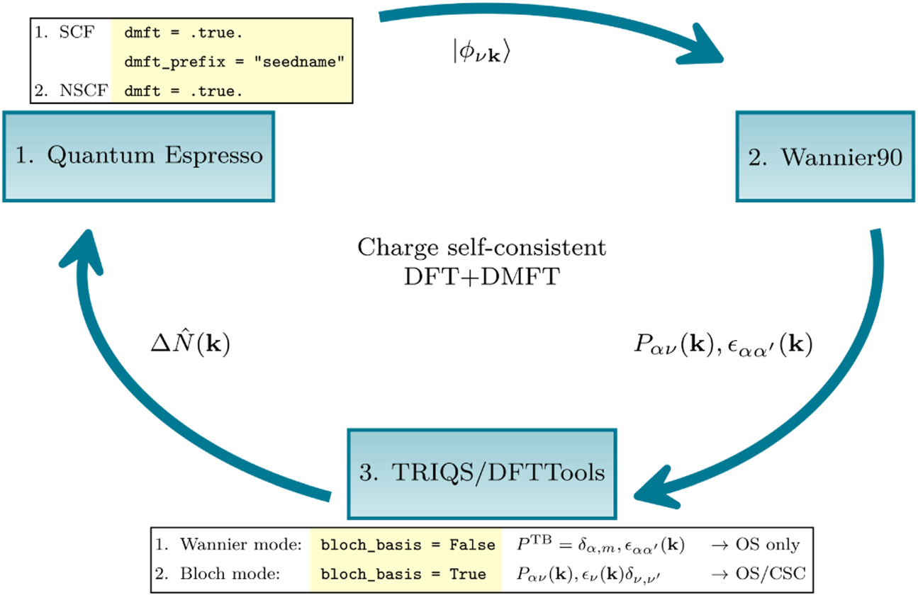
The workflow of the CSC calculation requires three software components, illustrated in figure 3 and described in the following. All additions are fully integrated in the respective open-source software packages.

Figure 3. Workflow of a fully CSC DFT + DMFT calculation (details explained in section 3).
Download figure:
Standard image High-resolution image3.1.1. QE—ground state preparation
The ground state density  is determined as usual in a self-consistent field (SCF) calculation. Following this, the user generates wavefunctions |ϕν
k
⟩ on a homogeneous k-point grid in an non-self-consistent field (NSCF) calculation as usual to interface with W90. Given the dmft = .true. Keyword in the NSCF system card (see section 3.1.4), QE will exit, but write the current wavefunctions and corresponding occupations to an hdf5 archive to keep a snapshot of the current state. This effectively allows to continue the calculation with updated occupations and wavefunctions in the next DFT step to obtain the next charge density as described in section 3.1.4. Note that the TRIQS/DFTTools converter expects the output named as seedname.nscf.out with verbosity = 'high' in the control card.
is determined as usual in a self-consistent field (SCF) calculation. Following this, the user generates wavefunctions |ϕν
k
⟩ on a homogeneous k-point grid in an non-self-consistent field (NSCF) calculation as usual to interface with W90. Given the dmft = .true. Keyword in the NSCF system card (see section 3.1.4), QE will exit, but write the current wavefunctions and corresponding occupations to an hdf5 archive to keep a snapshot of the current state. This effectively allows to continue the calculation with updated occupations and wavefunctions in the next DFT step to obtain the next charge density as described in section 3.1.4. Note that the TRIQS/DFTTools converter expects the output named as seedname.nscf.out with verbosity = 'high' in the control card.
3.1.2. W90
Subsequently, W90 is called with the same seedname, where the flags write_hr and write_u_matrices must be switched on to explicitly write the Hamiltonian  and matrices
  to file. This will create all necessary output files for the TRIQS/DFTTools converter.
3.1.3. TRIQS
The projector functions, together with the KS eigenvalues and other relevant information is read and written into hdf5 format (seedname.h5) using the Wannier90Converter in TRIQS/DFTTools. With an appropriate configuration file seedname.inp, which specifies the number of WFs, desired k-point grid, and the orbital character, the converter is run with a simple python script:

Importantly, the flag bloch_basis must be switched on for CSC calculations, determining whether the DMFT equations are formulated in the Bloch (True) or Wannier basis (False), as outlined in section 2.1.1 and illustrated in figure 3. By default the converter leverages the fact that the single-site impurity problems are block-diagonal in the site index i, meaning that they decouple and can be solved independently, but in principle they can also be set up as a cluster with off-diagonal elements.
After a number of self-consistent DMFT iterations the charge density correction (see equation (25)) is computed and stored directly in the existing seedname.h5 archive. This is handled again in TRIQS/DFTTools, using the SumkDFT class. This class provides lattice Green's function operations and for a detailed overview we refer the reader to reference [5]. The charge density correction is calculated by upfolding the impurity self-energy into the lattice Green's function (see equation (3)), determining the chemical potential, and then calling the function calc_density_correction provided within the SumkDFT class. This marks the endpoint of the DMFT cycle.
3.1.4. QE—continued
At this point QE is restarted in the SCF mode at the checkpoint whose creation was triggered at the end of the previous NSCF calculation with corresponding wavefunctions and occupations. Importantly, QE skips the determination of new wavefunctions, but computes the updated DFT + DMFT charge density (equation (30)) with the following key input parameters given:

In particular, the charge density corrections from DMFT are read from the seedname.h5 archive, and are used to obtain the unitary matrices  (equation (28)), which diagonalize the new occupations and consequently rotate the KS basis as defined in equation (29). Based on these new states, the code computes the updated charge density ρ(r) (equation (30)), which corresponds to the physical DFT + DMFT charge density as defined in equation (20). QE is stopped (electron_maxstep = 1), implying that no DFT self-consistency is reached. Instead, an NSCF calculation follows as described above, computing from ρ(r) a new Hamiltonian and corresponding single-particle states
  , where the superscript (1) labels the next generation of KS states to be downfolded. The procedure described in sections 3.1.2–3.1.4 is repeated until convergence. Importantly, no information is written to, or read from, text files, in contrast to currently existing DFT + DMFT interfaces, reducing I/O operations, making the procedure less error-prone, and eliminating the need of elaborate file parsing.
3.2. Installation and parallelization remarks
As outlined above the interface consists of two new software parts.
- (a)The first part of the interface is directly implemented in QE, starting with version 7.0. The compilation requires hdf5 support, since the data exchange between codes is handled on the level of hdf5 archives.
- (b)The second part is implemented in TRIQS/DFTTools, starting with version 3.1, which handles the actual conversion from the W90 output (see figure 3 right side). TRIQS/DFTTools is publicly available on GitHub at github.com/triqs/dft_tools and contains all the functionality discussed here. TRIQS/DFTTools is installed like any other TRIQS application. For explicit instructions see the documentation of TRIQS/DFTTools, which also contains an extensive tutorial on how to use the converter including example input files.
The W90 code does not require any modifications, and can be acquired via wannier90.org.
As outlined above the converter leverages MPI for parallelization over k-points. This also holds for all other components described above implemented in QE and TRIQS, making it scaling well with number of k-points. Hence, the converter should be called as mpirun python w90_converter.py.
A wrapper routine handling all parts of this workflow including a tutorial is available in the solid_dmft package [21], which is publicly available on github github.com/flatironinstitute/solid_dmft and is installed like any other TRIQS application.
4. Benchmarks
The results presented in this section are obtained using the implementation described above. The implementation is benchmarked for two systems where CSC was shown to affect the materials properties. The first example concerns the strain-induced orbital polarization in CaVO3, while the second benchmark reports the change in equilibrium volume in Ce2O3. We also report on the example of Sr2RuO4 where, in contrast, CSC is found to play a minor role with no changes in quasiparticle mass renormalizations.
- (a)Orbital polarization in CaVO3 We first investigate the strain-induced increase of orbital polarization in the orthorhombic d1 correlated metal CaVO3. Comparing OS (i.e. non CSC) versus CSC calculations, the authors in reference [16] reported a shift of the critical Umit for the metal–insulator transition of 0.2 eV upon introducing charge self-consistency, rendering the CSC solution less correlated, see blue and green lines and markers in figure 4. While in reference [16] the CSC calculations were performed only with the 'Vienna Ab initio Simulation Package' (VASP) [34–36], a comparison for OS to QE + W90 (in the Wannier-mode) was presented (purple lines and markers). Here, we extend this study to complete the comparison by including the CSC solution using QE + W90, see red lines and markers in figure 4. As in the previous study, all calculations were performed on a minimal t2g model at β = 40 (eV)−1, using the standard Hubbard–Kanamori interaction [37] with varying U and fixed J = 0.65 eV, and the continuous-time QMC hybridization-expansion solver [23] implemented in TRIQS/cthyb [38]. The computational details for the DFT calculation are described in appendix
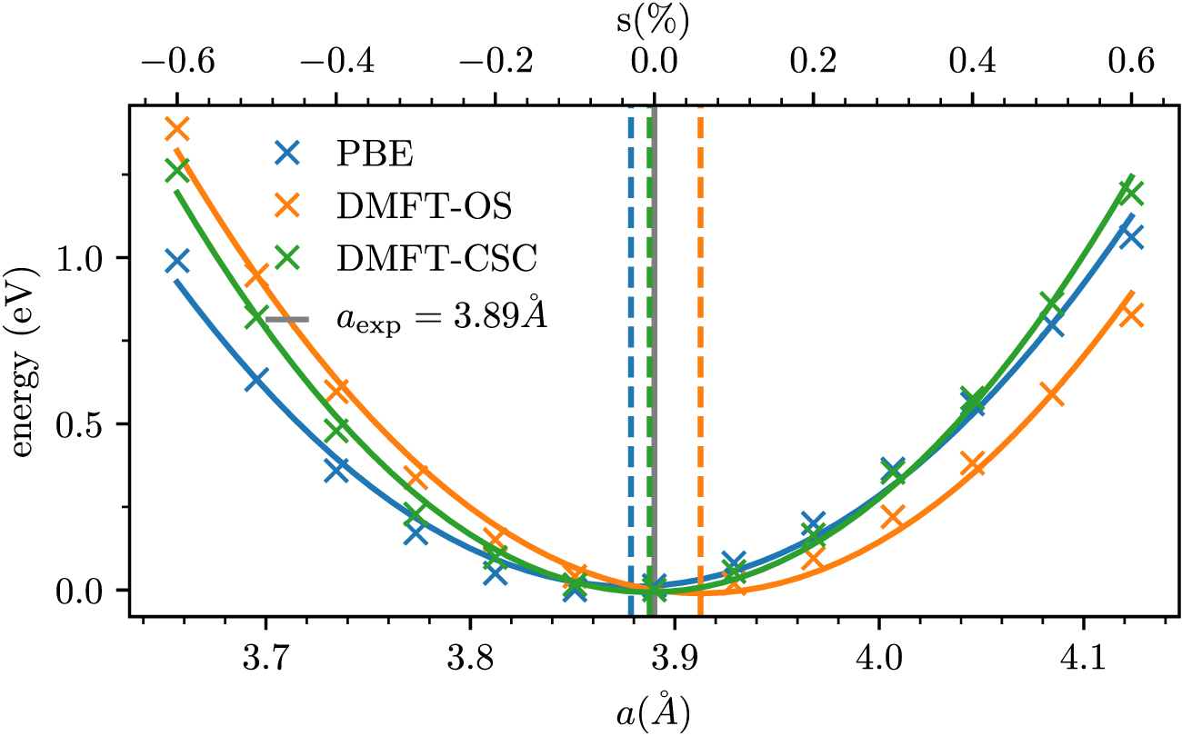
A1 . Note that this model is an example of an isolated subspace as defined in case 2 of section 2.1.2. As demonstrated in reference [16], the comparison between the VASP-internal projection to localized orbitals and the down-folding via W90 (DMFT in 'Wannier mode') shows excellent agreement for the OS case. With our implementation we confirm that a reduction of orbital polarization, in this case occupation of dxy with respect to dxz /dyz , occurs in CSC calculations with a shift of 0.2 eV, i.e. in excellent agreement to previous results.In figure 5 we compare the changes in the charge density with respect to the KS ground state density both for CSC and OS calculations, i.e. ΔρCSC(r) and ΔρOS(r), respectively, defined asBoth panels correctly represent the increase in orbital polarization, with a positive value for the dxy and a reduction for dxz /dyz orbitals, as compared to the ground state density. The comparison between CSC and OS in the left and right panel, respectively, further confirms that the magnitude of orbital polarization is overestimated in OS calculations (compare figure 4). Note that ρOS(r) was computed using equation (24) based on a fully converged OS calculation. We show the changes in the Wannier Hamiltonian (equation (16)) in figure 9. The visibly small modifications demonstrate that no major reconstruction takes place, that would require attention in the construction of the TB Hamiltonian. - (b)Total energy calculation of Ce2O3 The second example is given by total energy calculations of the equation of state for Ce2O3 as function of volume. Here, we compute the total energy for equidistantly spaced strain values between −0.6 to 0.6% for a low-energy Hamiltonian based on the correlated f-shell. The computational details for the DFT calculation are described in appendix
A2 . The low-energy model constitutes a fully isolated set of bands as described in section 2.1.2, case 2. The corresponding impurity problem is solved within DMFT with the Hubbard-I impurity solver at β = 2000 (eV)−1 using U = 6.46 eV and J = 0.46 eV. We use the fully localized limit as the DC correction formula as was previously done in reference [13, 18]. As is shown in figure 6, the DFT solution (blue lines and markers) slightly underestimates the equilibrium lattice constant obtained in the experiment, although it is already in very good agreement with a deviation of less than −0.5%. The equilibrium lattice constant then shifts to% in OS DMFT calculations (orange lines and markers). Finally, introducing full charge self-consistency the agreement to the experiment is almost perfect (green lines and markers). The minima of the quadratic fits are indicated by vertical dashed lines. The changes in the non-interacting bandstructure and charge density are displayed in figures 7 and 10, respectively, for the experimental volume. In comparison to the other two materials the magnitude of the changes in the largest in Ce2O3, with a change in ΔρCSC (equation (33)) twice as large as for CaVO3 in figure 5.We note that in comparison to references [13, 18] already the DFT equilibrium is much closer to the experimental value. This is attributed to the difference of exchange functionals from LDA to PBE [39], which are known to underestimate/overestimate lattice parameters, respectively. The shift to larger lattice parameters in the OS DMFT solution can be understood in terms of the expansion of 4f orbitals due to the local interaction, similar as in DFT + U. Finally, the CSC solution lies in between the DFT and the OS results, which one might intuitively expect if one considers the self-consistent solution as a mixture of the two extrema, the DFT solution on the one hand and the OS DMFT solution on the other hand. - (c)Quasiparticle mass renormalization in Sr2RuO4 We finally turn to Sr2RuO4, a metal displaying clear signatures of strong electronic correlations. Previous DMFT studies have established that the Hund's rule coupling (intra-atomic exchange) is responsible for these electronic correlations [40, 41], the proximity of a van Hove singularity also playing an important role [42]. Most previous studies have however been performed in OS mode without ensuring full charge self-consistency, with only a couple of published works [43, 44] mentioning that, indeed, charge self-consistency does not lead to significant modifications—a fact which is perhaps to be expected given the highly itinerant character and rather large bandwidth of this metal. Here, we document this in more details. Due to overlap of the Ru dxy orbital with oxygen p states, the construction of a Wannier model for the Ru t2g orbitals is an example of an entangled subspace as defined in case 3 of section 2.1.2. We focus here on key information about the nature of quasiparticles in this system, which can be extracted from a DMFT calculation, namely the quasiparticle mass renormalization. The impurity problem with Hubbard–Kanamori interactions is solved with the continuous-time QMC hybridization-expansion solver with the interaction parameters set as U = 2.3 eV and J = 0.4 eV. The computational details for the DFT calculation are described in appendix
A3 . In the OS calculation at β = 232 (eV)−1 (T = 50 K) the four electrons in the d-shell are equally distributed with very low polarization of between the dxy
and dxz
/dyz
orbitals, respectively. The corresponding self-energies are shown in figure 8 (orange and red, respectively). Fitting the first ten Matsubara frequencies to a polynomial of fourth order, the extracted slope at zero frequency results in an inverse quasiparticle mass renormalization of Z = 0.22/0.31 for the two orbitals, respectively. As expected, performing CSC calculations does not lead to a drastic change of these results. The orbital polarization changes less than 2%. Similarly, the inverse quasiparticle mass renormalization (blue and green in figure 8) increases minimally to 0.32 for the dxz
/dyz
orbitals. This is to be expected from the very small changes of the non-interacting Hamiltonian as shown in figure 11.


Figure 4. Reprinted (figure) with permission from [16], Copyright (2020) by the American Physical Society. Evolution of orbital occupation (top) and spectral weight at the Fermi level  (bottom) as function of interaction strength U in CaVO3. Comparison between OS and CSC calculations between VASP and the QE + W90 route. New data of the CSC implementation is marked as red lines and symbols. Solid, dashed and dotted lines refer to the three t2g orbitals (top panel).
Download figure:
Standard image High-resolution image
Figure 5. Isosurface plot of the charge redistribution in the VO2 layer (averaged over contributions ±3.75% of the z-axis lattice constant) in CaVO3 in Pbnm symmetry at U = 5.0 eV. Comparison between ΔρCSC (left) and ΔρOS (right) as defined in equations (33) and (34), respectively.
Download figure:
Standard image High-resolution image
Figure 6. Total energy calculations for hydrostatic strain in Ce2O3 using the PBE functional in DFT (blue), and OS- and CSC-type DMFT calculations in orange and blue, respectively. The experimental lattice parameter is shown as vertical grey line.
Download figure:
Standard image High-resolution image
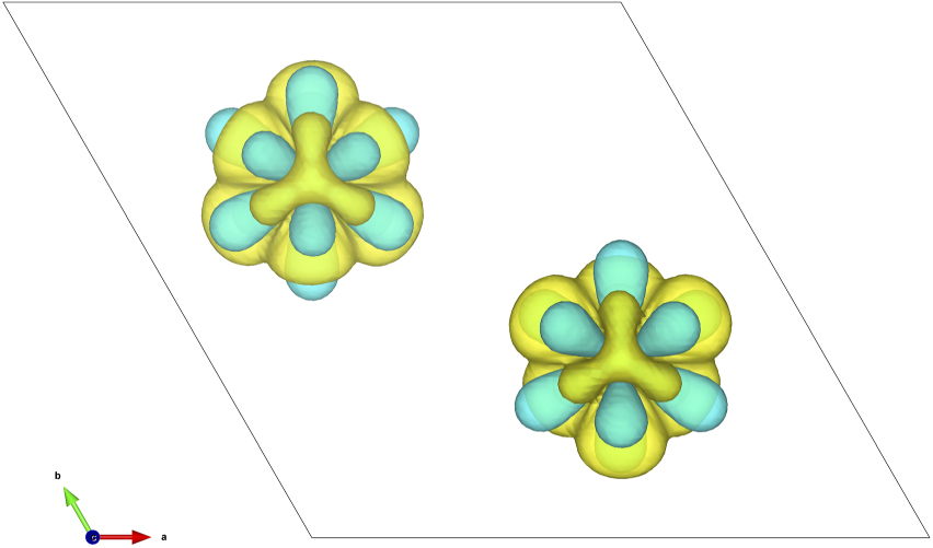
Figure 7. Top view of the isosurface plot of the charge redistribution ΔρCSC (equation (33)) in Ce2O3 at an isovalue of 7.8 × 10⁻³ electrons/bohr3. Yellow and cyan represent positive and negative changes, respectively.
Download figure:
Standard image High-resolution image
Figure 8. Comparison between OS (orange and red) and CSC (blue and green) of the imaginary part of the self-energy for the dxy and dxz orbitals in Sr2RuO4. Crosses correspond to numerical results, solid lines are fits of the first ten Matsubara frequencies to a polynomial of fourth order.
Download figure:
Standard image High-resolution image5. Conclusion
In conclusion, we have presented a new implementation for fully CSC DFT + DMFT calculations using a combination of the Quantum ESPRESSO (v.7.0), Wannier90 and TRIQS/DFTTools (v.3.1) software packages. Our approach unifies the Wannier-based and projector-based embedding methods. We note that in our approach the projectors are not necessarily confined to spheres around the projection center. For the sake of clarity, we have introduced a revised naming convention, Bloch- versus Wannier-mode, referring to the basis in which the DMFT equations are formulated in as a fundamental distinction.
While the overall implementation is tailored for the particular combination of codes, the path through Wannier90 is more general and can be combined with other DFT codes as well as TB approaches. It thereby allows to utilize standard tools included in or bridged to Wannier90, making this approach more flexible and appealing to a broader community. In comparison to a simpler projection scheme in the typical 'projector'-based approaches, it provides more control of the correlated subspace basis, allowing the user to define parameters of spread minimization or finding an optimally connected subspace in case of entanglement. A simple visual interface further allows to check the legitimacy of the subspace in representing the Kohn–Sham states correctly, which is often inaccessible in 'projector'-based formalisms.
We benchmarked the implementation for three different systems and showed that it produces excellent agreement to previously reported and published results based on existing implementations of different codes. The workflow is fully open-source and MPI-parallelized, which makes it ideally suited for a broader community and for studying larger systems.
Acknowledgments
SB is grateful to P Giannozzi, P Delugas and I Timrov for helpful comments and insightful discussions on the implementation in QE. The authors acknowledge helpful discussions with C Dreyer, J Bonini, M Morales, I Leonov and D M Korotin. This work was supported by ETH Zurich and the Swiss National Science Foundation through NCCR-MARVEL. Calculations were performed on the cluster 'Piz Daint' hosted by the Swiss National Supercomputing Centre. The Flatiron Institute is a division of the Simons Foundation.
Data availability statement
The data that support the findings of this study are available upon reasonable request from the authors.
Appendix A.: Computational method
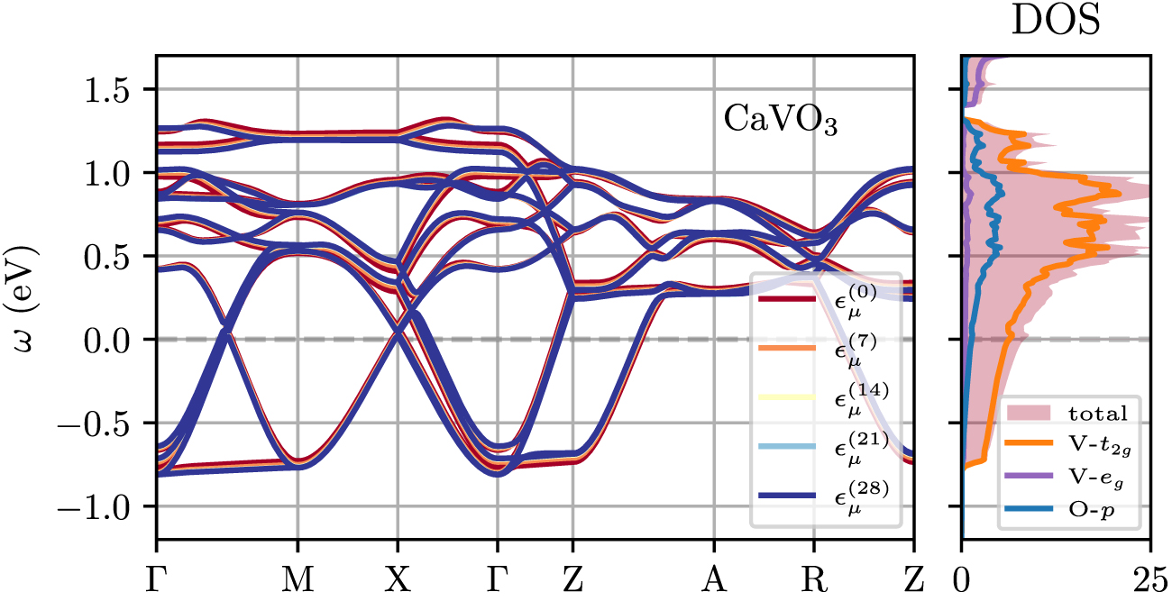
Here we provide the computational details of the DFT calculations for each of the benchmarked materials. Furthermore, we show the non-interacting bandstructure and density of states (DOS) for each compound. Note that only  in figures 9–11 represents the (Wannierized) bandstructure derived from a physical charge density, i.e. the ground state charge density ρ0(r). For the DOS we used the improved tetrahedron method on a grid that is a factor three denser than the original one.

Figure 9. Non-interacting bandstructure and DOS of TB Hamiltonian in band basis  (equation (16)) as function of CSC iteration for CaVO3.
Download figure:
Standard image High-resolution image
Figure 10. Non-interacting bandstructure and DOS of TB Hamiltonian in band basis  (equation (16)) as function of CSC iteration for Ce2O3 (experimental lattice constant).
Download figure:
Standard image High-resolution image
Figure 11. Non-interacting bandstructure and DOS of TB Hamiltonian in band basis  (equation (16)) as function of CSC iteration for Sr2RuO4.
Download figure:
Standard image High-resolution image
A1. CaVO3
We use the PBE functional [39] to calculate the electronic structure in the Pbnm (space group 62) unit cell. The in-plane lattice constants are constrained to  Å to impose tensile strain of 4.1%, while the c-axis of the cell and all atomic positions were relaxed, yielding
  Å. Cell parameters and internal coordinates are relaxed until all force components are smaller than 0.1 mRy/a0 (a0: Bohr radius) and until all components of the stress tensor are smaller than 0.1 kbar. We employ scalar-relativistic ultrasoft pseudopotentials, with the 3s and 3p (2s) semicore states included in the valence for both Ca and V (for O). The energy cutoffs for the wave functions and charge density are set to 70 Ry and 840 Ry, respectively. We use a 11 × 11 × 8 Monkhorst–Pack k-point grid to sample the Brillouin zone, and a smearing of 0.015 Ry in the Methfessel–Paxton scheme. We use the lowest 98 electronic states throughout the calculations. The corresponding non-interacting bandstructure and DOS are shown in figure 9 in left and right panel, respectively.
A2. Ce2O3
We use the PBE functional [39] to calculate the electronic structure in the  (space group 164) unit cell. We use the experimental unit cell with
  Å and
Å and  Å [45]. To simulate the effect of hydrostatic pressure these values are scaled from −0.6 to 0.6%. We employ scalar-relativistic ultrasoft pseudopotentials, with the 5s, 6s, 5p and 4d (2s) semicore states included in the valence for Ce (for O). The energy cutoffs for the wave functions and charge density are set to 100 Ry and 1100 Ry, respectively. We use a 8 × 8 × 4 Monkhorst–Pack k-point grid to sample the Brillouin zone, and a smearing of 0.01 Ry in the Methfessel–Paxton scheme. We use the lowest 50 electronic states throughout the calculations. The corresponding non-interacting bandstructure and DOS are shown in figure 10 in left and right panel, respectively.
A3. Sr2RuO4
We use the PBE functional [39] to calculate the electronic structure in the I4/mmm (space group 139) unit cell. Cell parameters and internal coordinates are relaxed until all force components are smaller than 0.1 mRy/a0 (a0: Bohr radius) and until all components of the stress tensor are smaller than 0.1 kbar, yielding a lattice constant of  Å. We employ scalar-relativistic ultrasoft pseudopotentials, with the 4s and 4p (2s) semicore states included in the valence for both Sr and Ru (for O). The energy cutoffs for the wave functions and charge density are set to 60 Ry and 720 Ry, respectively. We use a 12 × 12 × 12 Monkhorst–Pack k-point grid to sample the Brillouin zone, and a smearing of 0.01 Ry in the Methfessel–Paxton scheme. We use the lowest 36 electronic states throughout the calculations. The corresponding non-interacting bandstructure and DOS are shown in figure 11 in left and right panel, respectively.
Appendix B.: Differences TB and Bloch formulation of DMFT equations
Here, we demonstrate that writing the DMFT equations in orbital basis is equivalent to a formulation in Bloch basis if and only if the projector functions  are unitary, in which case one can skip the upfolding of the self-energy in equation (3) and trivially obtain the k-dependence of the self-energy.
In operator notation the lattice Green's function is defined as

We express equation (4) without k-summation in operator notation as

where TB and KS refer to the lattice Green's function in TB and KS basis, respectively. If  is unitary, the last line reduces to

in which case the projector functions can be applied just once to down-fold the KS Hamiltonian as in equation (14),

Only in this case the impurity self-energy obtains a trivial k-dependence as

This formalism is readily extended to multiple impurity sites i with block-diagonal impurity Hamiltonians. The resulting self-energy in  is block-diagonal, too, meaning that the up-folding in equation (3) can be done independently for each block/site, i.e. the matrix multiplication separates into a sum over blocks/sites i with corresponding rows of the projector functions.