


Abstract
We present an experimental study on the ultra-narrow bandwidth tunable atomic filter with electromagnetically induced transparency at 795 nm in rubidium vapor. The filter achieves a peak transmission of 8% and a linewidth of 15 MHz. The transmission peak can be tuned within the range of the Doppler linewidth. There is just one transmission peak, all other frequencies of light cannot pass through the filter.
Export citation and abstract BibTeX RIS
Changes were made to this article 21 May 2015. The corresponding author information was amended
1. Introduction
Atomic optical filter plays a key role in modern communication systems such as free-space quantum key distribution (QKD) [1, 2], remote sensing [3, 4], and lidar systems [5]. Narrowband Faraday anomalous dispersion optical filters (FADOFs) are based on the Faraday anomalous dispersion effect and the Zeeman effect, which consist of an atomic vapor cell between two crossed polarizers in a homogeneous longitudinal magnetic field. Incident light is prevented by the crossed polarizers. When the magnetic field is applied, the Zeeman shifts lead to a difference between the resonance frequencies for the left and right circular polarizations. Accordingly, the refractive indexes for the two circular polarization components are different, which signifies a difference in phase velocities of the two circular components of light and, as a result, a net rotation for the polarized light while passing through the cell can be achieved. Only the light that has a rotation of π/2 can go through the filter. FADOFs have many advantages such as narrow bandwidth, high peak transmission, high background rejection [4], and wide field of view.
As a very efficient filter device, FADOF was first introduced by Ohman in 1956 [6] and has been developed for several atomic resonances, for example, Na D lines [7, 8], three K lines [9–11], Rb lines [11–13], Cs lines [14, 15] and Ca lines [16]. However, the bandwidth of FADOFs is limited at GHz level or at least in hundreds of MHz. To obtain a narrower bandwidth, several advanced approaches have been utilized to the FADOF, such as ultra-narrow bandwidth atomic filter with Raman light amplification [17] which achieves a linewidth of 60 MHz, and narrowband switchable dual-passband atomic filter with four-wave mixing optical amplification [18] which achieves a linewidth of 120 MHz.
Unfortunately, for a conventional FADOF, there could be many transmission peaks at the same time. Take rubidium D1 line for example, there are six absorption peaks and each absorption peak corresponds to a transmission peak because the similar anomalous dispersion curves at different resonances [11, 19]. When we choose one transmission peak as the signal, the other peaks become the noise signal. Although most literatures do not mention this, the multimodal transmission is a great weakness of the conventional FADOFs. Therefore, any atomic filter with narrower bandwidth, higher transmission, and single transmission peak would be highly demanded.
In this paper, we propose and demonstrate experimentally an ultra-narrow bandwidth atomic filter with electromagnetically induced transparency (EIT) [20]. EIT was first proposed by Harris and attracted great attention due to its wide application in atomic clocks [21, 22], magnetometers [23], quantum optics [24, 25], and quantum communications [26–28].
Although the theory of EIT has been thoroughly investigated, we will briefly sketch the theoretical treatment in order to clarify how the EIT affects the characteristic of the filter. A three-level  system in 87Rb D1 line is considered as shown in figure 1(a). One laser beam with frequency
  couples the ground state
  and the excited state
  as the probe field, and another one with frequency
  couples the ground state
  and the excited state
  as the coupling field. With the effect of the strong coupling field, the EIT can be observed. In figure 1(b), the blue line shows the transmission as a function of the probe frequency in the presence of a fixed-wavelength coupling. We see that at the center frequency the strong absorption vanished. And at the point of vanishing absorption the steep slope of the refractive index (dispersion) as a function of frequency is shown as the black line in figure 1(b). Because of the action of the coupling field, the dispersion is much steeper than the case without the coupling field. When a low magnetic field is applied, the small Zeeman shifts lead to enough difference of the refractive index between the two circular polarizations, which could cause the polarization plane of the incident probe light rotated to π/2. Because of the very steep slope of the refractive index near the EIT transparency window, the application of EIT provides many advantages. For example, the bandwidth of our filter is about 15 MHz only, which is approaching the natural linewidth; the experimental conditions are simple with temperature of 313 K and very weak magnetic field of 10 gauss; the transmission frequency can be tuned slightly with the coupling light frequency in the Doppler profile of the absorption line of rubidium; there is just one transmission peak in the EIT transparency window only, and all other frequencies of light cannot pass through the filter because the application of EIT.
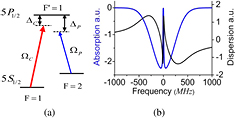
Figure 1. (a) Energy-level scheme:  and
and  are Rabi frequencies of the coupling and the probe light, respectively;
  and
and  are detunings of the coupling and the signal light, respectively. (b) The absorption (blue line) and the dispersion (black line) curves of EIT.
Download figure:
Standard image High-resolution image2. Experimental setup and results
The construction of the experimental setup of this atomic optical filter is shown in figure 2. ECDL1 and ECDL2 are DL-100 external-cavity diode lasers and provide the probe field at 794.9686 nm and the coupling field at 794.9826 nm, respectively. The filter consists of a rubidium vapor cell (Rb cell 1: 20 mm in diameter and 50 mm in length) between two crossed Glan–Thompson polarizers (PBS1 and PBS2, PBS2 is rotatable), which subjects to a homogeneous magnetic field along the optical path. The coupling and the probe lasers co-propagate through the Rb cell 1 with an angle of about 0.01 rad. Beam diameters of the probe and coupling fields are about 1 and 3 mm, respectively, and their linewidths are  1 MHz. The two laser beams are orthogonally polarized. Operation temperature of the Rb cell 1 is kept at 313 K during the experiment. The filter transmitted signals are detected using a photodiode detector PD1. The output is recorded by a digital oscilloscope. The Rb cell 2 (20 mm in diameter and 50 mm in length) and PD2 are used to monitor the coupling signal.
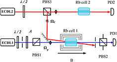
Figure 2. Schematic of the experimental setup.  : half-wave plate; PBS, polarizing beam splitter; PD, photodiode; A is an attenuator.
Download figure:
Standard image High-resolution imageFirst, the magnetic-field strength was set to zero and the two polarizers PBS1 and PBS2 were set parallel to each other. The absorption was observed by PD1 as trace 1 (the blue line) shown in figure 3, a narrow EIT window can be observed clearly. Then set the two polarizers PBS1 and PBS2 perpendicular to each other, and set the magnetic field strength to 10 gauss, the transmission spectrum of the filter based on EIT was observed as trace 2 (the red line) shown in figure 3 and trace 3 (the red line) in figure 4. The full-width at half-maximum (FWHM) of the transmission peak is about 15 MHz, which is 1% of the conventional FADOF only. And the transmission is about 8%.
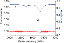
Figure 3. Trace 1 (the blue line): probe absorption of the rubidium D1 line as a function of the probe frequency detuning with the coupling field on; Trace 2 (the red line): transmission spectra of the filter based on electromagnetically induced transparency.
Download figure:
Standard image High-resolution image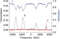
Figure 4. Trace 1 (the blue line): probe absorption spectra of rubidium D1 line as a function of the probe frequency detuning without the coupling field; Trace 2 (the black line): transmission spectra of conventional FADOF without coupling field on. Trace 3 (the red line): transmission spectra of the filter based on electromagnetically induced transparency.
Download figure:
Standard image High-resolution imageWhen the coupling field is blocked, the conventional FADOF could be observed. In figure 4, trace 1 (the blue line) shows the absorption peaks of Rb D1 line (PBS1 and PBS2 were set parallel to each other); trace 2 (the black line) shows the transmission spectra of a conventional FADOF in the absence of the coupling laser for a cell at a temperature of 313 K and magnetic field of about 150 gauss. The four transmission peaks are corresponding to the transmissions of 87Rb  →
→  , 85Rb
  →
→ 
 , 85Rb
  →
→  and 87Rb
  →
→  . The FWHM of a single transmission peak is about 600 MHz while the separation between two peaks is 1 GHz or 2 GHz. This means the four peaks can get through the filter simultaneously and the bandwidth of the FADOF is ~7 GHz. Trace 3 (the red line) shows the transmission spectra of the filter based on EIT with both probe and coupling lasers on at a temperature of 313 K and magnetic field of 10 gauss. There is one transmission peak in the EIT transparency window only. All other frequencies are blocked by PBS2. Not only that, when the coupling frequency is changed to couple other atomic transmission, the EIT transparency window will move to the corresponding absorptions. And the transmission peak of the filter will be moved simultaneously. Theoretically, we can get the filter based on EIT transmission at all the absorption lines. But for 87Rb D1 line, the experimental result at the first and the sixth absorption line are better than that at the second and fifth absorption line for the non-equilibrium population distribution of the atoms in the vapor.
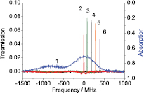
The transmission frequency of the Faraday anomalous dispersion optical filter based on EIT can be tuned slightly with the coupling light frequency. The location of the EIT transparency window depends on the detuning of the coupling light. So as the transmission frequency of the filter can be changed by tuning the coupling detuning. In figure 5, trace 1 (the blue line) is the atomic absorption line with Doppler broadening; trace 2 (the red line) is the transmission peak with no coupling laser detuning from 87Rb  →
→  ; traces 3, 4, 5 and 6 are transmission peaks of the filter based on EIT with the coupling laser blue detuned from
  →
→  . In the case of the coupling laser being red detuned from
  →
→ we can get similar results. The transmission rate decreases with the coupling detuning. And the larger frequency detuning is, the faster the transmission rate decreases. The filter extinction outside the transmission window for the EIT signal is very weak at those frequencies.
Figure 5. Trace 1 (the blue line): probe absorption spectra of rubidium D1 line without the coupling field; Trace 2, 3, 4, 5 and 6 (the red, green, black, yellow and purple lines): transmission spectra with different coupling-light frequencies.
Download figure:
Standard image High-resolution image
3. Discussions
Here we will discuss some parameters which could influence the outcome of the experiment. Firstly, according to previous research of EIT, to get a better result on the experiment the coupling beam and the probe beam should propagate collinearly. But in our experiment the PBS2 was designed rotatable to enable us to detect the absorption signal (EIT signal) and the filter transmitted signal. If the two beams propagate collinearly there must be a case that the coupling beam through the PBS2 and detected by PD1. Then the weak probe signal would be buried in the strong coupling light. So the two lasers must be propagated with a small angle as figure 2 shows. The angle is as small as possible but must enable the coupling beam to be blocked by the circular aperture before PBS2.
Secondly, the intensity of the coupling laser fields can significantly influence the outcome of the experiment. In our experiment the coupling laser beam is about 10 mW and the probe laser beam is about 0.1 mW. The transmission of the filter increases with the increase of the intensity of the coupling field. Theoretically, we can achieve the same result by decreasing the intensity of the probe field. But if the probe laser is too weak, it is hard to obtain the filter transmitted signal. When the intensity of the coupling field increased, the linewidth of the filter would be broadened slightly in theory.
Thirdly, the filter based on EIT is under the condition of low-intensity magnetic field. The transmission is very sensitive to the magnetic field. A minor change in the strength of the magnetic field may affect the filter transmission. The effect to the linewidth is not distinct. The key to realize the filter based on EIT is to find the suitable intensity of the magnetic field.
4. Conclusions
In conclusion, we have experimentally present an ultra-narrow bandwidth atomic filter based on EIT operating at the rubidium D1 line. The application of EIT makes this filter and the FADOFs obviously different. (1) It gives a more narrow-bandwidth. The transmitted bandwidth of conventional FADOFs are in GHz level, the Doppler broadening. While the filter based on EIT gives a transmitted bandwidth of 15 MHz which is approaching the natural linewidth. (2) The new scheme can be realized more easily with low intensity magnetic field than the FADOFs. (3) There are always two or more transmission peaks in the conventional FADOFs simultaneously. While the transmission of the filter based on EIT always transmits as a single peak at the EIT transparency window frequency. All other frequencies of light cannot pass-through the filter. (4) The transmission frequency of the filter can be tuned by changing the coupling frequency.
Acknowledgments
The authors would like to acknowledge the financial support from the National Basic Research Program of PRC (Grant No.2011CB921603), the National Natural Science Foundation of China (Grant No.11074097).