
Abstract
Multilayered structures are increasingly used in MEMS. Based on the resonant frequency of the doubly–clamped multilayered beam, the Young's modulus and residual stress for an individual layer have been measured by designing beam test structures for each layer with different widths. Taking into account the buckling or no buckling problem of the multilayered beam, this paper introduces a model for the resonant frequency of the beam. An approach to extract the Young's modulus and residual stress for the individual layer is developed. The validity of this approach has been studied using finite element modeling. As a multilayered example, test structures for a gold/polysilicon bilayer beam were fabricated. A scanning laser Doppler vibrometer system was used to measure the resonant frequency of the beam. The extracted parameters are that the average value of Young's modulus of polysilicon and gold are 133.7 GPa and 78.6 GPa with standard deviation being 4.2 GPa and 11.5 GPa, respectively; the average value of residual stress of polysilicon and gold are 13.9 MPa (compressive) and 19.7 MPa (tensile) with standard deviation being 0.47 MPa and 4.4 MPa, respectively.
Export citation and abstract BibTeX RIS
1. Introduction
Recently, multilayered structures have been utilized in MEMS. Researched applications include uncooled microcantilever infrared focal plane arrays [1], radio frequency (RF) components [2], micromachined mirrors [3], etc. It is well known that MEMS devices are highly dependent on factors such as the Young's modulus and residual stress of the multilayered films. These properties determine both the final shape and the functionality of released micromachined structures, and should therefore be accurately assessed. The Young's modulus and residual stress for the single layer film have been widely studied by the cantilever deflections, wafer curvatures, displacements of variously designed microstructures, buckling lengths, membrane deflections, resonance frequency, pull-in voltages and fixed-fixed beam deflections. However, these methods are not easily extended to multilayered films. The Young's modulus of multilayered films has been measured without the residual stress [4–7], while the residual stress for multilayered films has been studied but still requires the Young's modulus of each layer to be known [8–12]. It is more desirable to directly measure both the Young's modulus and residual stress for the multilayered films simultaneously. An attempt has been made to characterize these two mechanical properties by the pull-in voltages [13, 14] or resonant frequency [15]. The resonant frequency of the multilayered beam fixed at two ends varies with the dimensions of the beam. By designing beam test structures for each layer with different widths, the Young's modulus and residual stress for an individual layer may be extracted by the measured resonant frequency of the multilayered beam. Taking into account the buckling or no buckling problem of the multilayered beam, this paper first introduces a model for the resonant frequency of the beam for each layer with different widths. An approach to extract the Young's modulus and residual stress for the individual layer is then developed. The validity of this approach has been studied using finite element modeling (FEM). As a typical example, test structures for a metal (gold)/polysilicon bilayer beam were fabricated using MEMSCAP PolyMUMPs process. A Polytech scanning laser Doppler vibrometer (LDV) system with hardware modules of MSV-400-M2 was used to measure the resonant frequency of the beam. The results show the proposed method produces results that agree with the values most often given in the literature.
2. Model
This method uses multilayered micromachined doubly clamped beams that are excited to resonance and are measured using a scanning LDV. The resonance frequency predicted by a composite-beam model is used to extract the Young's moduli and stresses of all the individual thin-film layers in the beam. To easily extract these material parameters, test structures for the doubly–clamed beams with different widths are designed. Figure 1 shows the cross-section of the beam with different widths. The length of the beam is l. The width, thickness, density, Young's modulus, residual stress and Poisson's ratio of the ith layer film are bi, hi, ρi, Ei, σi, ѵi, respectively. Here a positive stress represents the tensile and a minus stress represents the compressive.
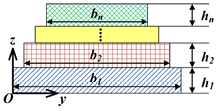
Figure 1. Cross-section of an n-layer beam with different widths.
Download figure:
Standard image High-resolution imageIn the designed test structures, since the width of the beam is bigger than five times thickness of the beam, the beam is considered to be wide, and Young's modulus Ei is replaced by the effective Young's modulus  , i.e.
In this study, the effective Young's modulus  is used instead of the Young's modulus Ei. If the height direction of the beam is assumed to be along z axis, and the position of the beam bottom, z0, is 0 while the position of the top of the ith layer is zi and the distance between the neutral axis and the bottom of the beam is zc. It yields
According to the static equilibrium condition of the forces, zc can be written as [16]
Then the moment of inertia of ith layer, Ii, with respect to the neutral axis of the beam is given by
where Ai is the cross-section area of the ith layer. For a multilayered beam, the bending stiffness,  , the axial stiffness,
  , the linear density,
  , and the axial load,
  , are defined by the sum of the individual terms for each layer in the beam as follows [6]
As is well known [17], in the beam theory there is an nth critical buckling load  defined as the axial force sufficient to maintain the beam in a slightly bent form. When the axial load P is greater than the critical value
 , the beam remains straight. And if
  (i.e.,
  ), the beam is initially statically deflected and a postbuckling displacement
  is induced, where b is the dimensional scaling constant and
  is the nth buckling mode shape. These two cases will be discussed below.
2.1. Initially flat beam
For an unbuckled beam, the axial load P =  is greater than the critical value
  , so the beam remains flat. For the undamped beam with a uniform cross section along its length, the natural frequencies ω for the initially flat beam is given by the eigenvalues [18]
where
Here the matrix in equation (9) is considered to be S.
2.2. Buckled beam
For the buckled beam,  , the beam will buckle and a postbuckling displacement
  is induced. The natural frequencies ω for the buckled beam is given by the eigenvalues [17, 19]
where
Here the matrix in equation (11) is considered to be B.
2.3. Extraction of material properties
The matrices in equations (9) and (11) are defined as S and B respectively, equations (9) and (11) can be rewritten as


where  represent the effective moduli and residual stresses of each layer, respectively, and
  is the natural frequency. Since equations (13) and (14) indicate that the natural frequencies are dependent of the material properties and geometries of the beam, the Young's modulus and residual stress of each layer of the composite beam can be extracted by using natural frequencies of a set of beams with different geometries. For an n-layer composite beam, at least two kinds of beams with different lengths are needed, and each kind of beam with the same length needs at least n different types in widths. If the widths of each layer in the jth beam are assumed to be
  and those in the kth beam with the same length as the jth beam are
  , it is required that the vector
  and vector
  must be linearly independent. It is well known that for a single-layer beam when n equals to 1, it is not restricted by this principle. So at least 2n kinds of beams are needed. The natural frequencies of these beams are required, and deflection profiles of these beams need to be observed so as to determine equation (13) or equation (14) to be used. Once the natural frequencies of the designed test structures are measured, the Young's modulus and residual stress of each layer for the composite beam can be extracted by numerical methods such as the Newton iteration method or least-square method. Generally, there are infinite solutions (Young's modulus E and residual stress σ) to the above equation. However, for an engineering problem, for example, the Young's modulus of the polysilicon has been reported in the range of 120 Gpa~201 GPa. Therefore, only one solution will be in this range. This solution is what we want. For the bilayered beam there are four unknowns (two Young's moduli and two residual stresses), four beams with different (length and width) dimensions are needed. If it is assumed that the Young's modulus and residual stress are the same for the each layer of the four beams because they are located close to each other, we have
In the experiments, we measured and obtained four different fundamental frequencies (ω11, ω21, ω12, ω22) for the four beams by a scanning LDV. Then, we can extract the two Young's moduli and two residual stresses for the bilayered beam according to the solving flow. In the experiments, by using a digital holographic microscope (DHM, R2200), initially flat or buckled beams were checked so that equation (13) for the initially flat or equation (14) for the buckled beams could be selected.
3. Simulation
To verify the proposed approach, analysis of doubly clamped bilayer beams as an example were simulated by FEM. Figure 2 shows a model for the doubly clamped bilayer beam, where the bottom layer is polysilicon and the top layer is gold. Four different beams in length and width are taken so that the Young's moduli and residual stresses of both layers can be extracted. Input parameters of the beams for the simulation are listed in table 1. To distinguish between the initially flat and buckled conditions, the simulations are carried out three times with two different pairs of residual stresses acting on the beams. Using the parameters in table 1, the fundamental frequencies and deflection profiles of the beams are obtained in FEM simulations by Ansys. The results are then put back into equations (13) or (14) to figure out the Young's moduli and residual stresses. Table 2 lists the comparison between materials properties set to the FEM analysis and those calculated from FEM analysis. It is clear from table 2 that the relative errors are less than 23%.

Figure 2. A doubly clamped bilayer beam in Ansys.
Download figure:
Standard image High-resolution imageTable 1. Parameters of a bilayer beam.
| Parameters | Polysilicon | Gold |
|---|---|---|
| Young's modulus (GPa) | 158 | 79 |
| Residual stress (MPa) | 20 | 20 |
| −20 | −20 | |
| Poisson's ratio | 0.22 | 0.44 |
| Density (kg m−3) | 2230 | 19300 |
| Beam length (µm) | 400 | 400 |
| 300 | 300 | |
| Width (µm) | 20 | 14 |
| 20 | 10 | |
| Thickness (µm) | 1.5 | 0.5 |
Table 2. Comparison of the set and calculated values.
| Materials properties | Set values | Calculatedresults | Relative error |
|---|---|---|---|
| Young's modulus (GPa) for polisilicon | 158 | 149.2 | 5.57% |
| Young's modulus (GPa) for gold | 79 | 82.7 | 4.68% |
| Residual stress (MPa) for polisilicon | 20 | 24.5 | 22.5% |
| Residual stress (MPa) for gold | 20 | 17.9 | 10.5% |
| Young's modulus (GPa) for polisilicon | 158 | 132.8 | 15.9% |
| Young's modulus (GPa) for gold | 79 | 85.5 | 8.22% |
| Residual stress (MPa) for polisilicon | -20 | −16.9 | 15.5% |
| Residual stress (MPa) for gold | -20 | −22.3 | 11.5% |
4. Experiments and discussions
Test structures were fabricated using MEMSCAP PolyMUMPs process. Layer Poly2 and layer Metal were used as structural materials. Both bilayer and single-layer doubly clamped beams were fabricated. For the bilayer beams, two kinds of lengths were applied while for the beams with the same length but different widths of layer Metal. And additional single-layer beams were also provided, which can be treated as the 0 width of layer Metal. Parameters of the test structures are listed in table 3. Scanning electron microscopy (SEM) photographs of the test structures are shown in figure 3. All the measurements were performed at room temperature.
Table 3. Test results for the bilayer beams
| Parameter | Lengths (µm) | Widths (µm) | Initially flat or buckled | Frequency (Hz) | |
|---|---|---|---|---|---|
| Poly2 | Metal | ||||
| Beam 1 | 200 | 10 | 0 | Flat | 110250 |
| Beam 2 | 250 | 10 | 0 | Buckled | 111875 |
| Beam 3 | 300 | 10 | 0 | Buckled | 137688 |
| Beam 4 | 400 | 20 | 14 | Buckled | N/A |
| Beam 5 | 400 | 20 | 10 | Buckled | 39688 |
| Beam 6 | 300 | 20 | 14 | Flat | 64531 |
| Beam 7 | 300 | 20 | 10 | Flat | 52969 |
aThe thickness, density and Poisson's ratio for Poly2 are 1.5177μm, 2330 kg/m3 and 0.22, while the ones for Metal are 0.5447μm, 19300 kg/m3 and 0.44, respectively[20].
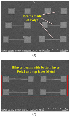
Figure 3. SEM photographs of the test structures. (a) Single-layer beams fabricated in layer Poly2. (b) Bilayer beams made up of Poly2 and Metal.
Download figure:
Standard image High-resolution imageTo determine the deformation of the beams, a DHM (R2200) from Lyncée Tec was used. The setup of the DHM system is shown in figure 4. The DHM can produce an off-axis hologram through the interference between the wave reflected by the sample and a reference wave. Figure 5 shows a 3 D image of one buckled beam. The profiles of the beams extracted from the DHM measurement are depicted as shown in figure 6. It can be observed clearly that some profiles of the beams are similar to a cosine curve, while the other profiles gently bend like bows. Due to the step-up support of the beams introduced by the surface micro-machined fabrication process, the doubly clamped beams applied with a slightly compressive load before buckling will have a small deformation rather than keep straight [21]. Hence the beams with profiles like cosine curves are considered as buckled and others slightly bent are treated as initially flat beams. The observation results are summarized in table 3.
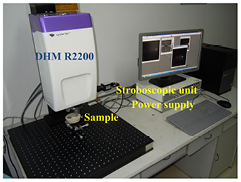
Figure 4. DHM system setup.
Download figure:
Standard image High-resolution image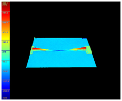
Figure 5. A 3D image of one buckled beam.
Download figure:
Standard image High-resolution image
Figure 6. Profiles of the beams extracted from the DHM measurement.
Download figure:
Standard image High-resolution imageAfter the deformation profiles were tested, resonant frequencies of the beams were then measured. A Polytech scanning LDV system with hardware modules of MSV-400-M2 was used. The setup of the LDV system is shown in figure 7. The test structures were excited by a piezoelectric plumbum zirconate titanate (PZT) ceramic slice with a periodical chip signal. By applying driven signal with frequencies ranging from 1 kHz to 1 MHz, the resonant frequencies were extracted from the frequency response functions [22]. Figure 8 shows the frequency response curve of a bilayer beam with length of 300 μm. The fundamental frequencies of six beams were measured. The measured fundamental frequencies are listed in table 3.

Figure 7. LDV system setup.
Download figure:
Standard image High-resolution image
Figure 8. The frequency response curve of a bilayer beam with length of 300 μm.
Download figure:
Standard image High-resolution image
With the measured results, the effective moduli and residual stresses were extracted simultaneously by equations (13) or (14). There are 12 types of combinations in total, made up of four beams out of the whole six ones, which forms 12 groups of solvable equations from equations (13) or (14). The Young's moduli and residual stresses of both layers are then extracted. The beam combinations and calculated results are listed in table 4. The results show the proposed method produces results that agree with the values most often given in the literature. For example, the Young's modulus of gold in this experiment coincides with 78 GPa as reported in [23].
Table 4. Extracted results from the measurements.
| Combinations of beams | Young's modulus of Poly2 (GPa) | Young's modulus of Metal (GPa) | Residual stress of Poly2 (MPa) | Residual stress of Metal (MPa) |
|---|---|---|---|---|
| 1, 2, 5, 6 | 133.2 | 99.0 | −13.3 | 12.2 |
| 1, 2, 5, 7 | 133.2 | 87.9 | −13.3 | 14.6 |
| 1, 2, 6, 7 | 133.2 | 57.2 | −13.3 | 27.7 |
| 1, 3, 5, 6 | 135.5 | 90.3 | −13.7 | 15.9 |
| 1, 3, 5, 7 | 135.5 | 84.6 | −13.7 | 17.2 |
| 1, 3, 6, 7 | 135.5 | 68.1 | −13.7 | 24.2 |
| 1, 5, 6, 7 | 138.4 | 80.6 | −14.3 | 20.4 |
| 2, 3, 5, 6 | 139.3 | 82.7 | −14.1 | 18.1 |
| 2, 3, 5, 7 | 139.3 | 79.4 | −14.1 | 18.9 |
| 2, 3, 6, 7 | 139.3 | 68.6 | −14.1 | 23.6 |
| 2, 5, 6, 7 | 142.8 | 74.9 | −14.5 | 21.4 |
| 3, 5, 6, 7 | 146.9 | 69.8 | −14.7 | 22.4 |
| Averages | 137.7 | 78.6 | −13.9 | 19.7 |
| Standard deviation | 4.2 | 11.5 | 0.5 | 4.4 |
| References 20–24 | 120~201 | 78 | −18~-1 | 5~166 |
There are some factors that may affect the accuracy of the extraction model. First of all, squeezed damping in air may lead to the measured resonant frequency to shift from the expected value [22]. To reduce this deviation, the amplification factor for the frequency response functions at points of the resonant frequencies are required to be more than 20, and in this situation the error caused by the frequency shift will be less than 0.01%. Secondly, compliance of step-up support fabricated by the surface micro-machined fabrication process may cause a relaxation of residual stresses. It is reported that under a compressive biaxial residual stress of 11 MPa, the relaxed stress is about 9 MPa as beam length is 1000 μm, while the relaxed stress decreases to 3 MPa as beam length decreases to 500 μm [25]. In this study, lengths of doubly clamped beams are less than 400 μm. Hence, the relaxation of residual stress in the test structures is small and acceptable.
5. Conclusion
In this paper, an approach is presented to measure the Young's modulus and residual stress of an individual layer for MEMS composite films. A theoretical model for extracting material properties by resonant frequencies of doubly clamped multilayered beams is analyzed. Material properties for the composite films can be obtained by a set of doubly clamped beams with different lengths and widths. Both initially flat and buckled beams have also been considered. The validity of the proposed method has been confirmed by the finite element analysis and experiments. This method is suitable for monitoring the MEMS fabrication process.
Acknowledgements
This project is partly supported by the National Science and Technology Major Project under contract no. 2011ZX02507.