

Abstract
Enhancement of thermal spin transfer torque in a double-barrier magnetic tunnel junction with a nonmagnetic-metal spacer is proposed in this study. The results indicate that, given the same temperature difference, thermal spin transfer torque and charge current density for the proposed double barrier magnetic tunnel junction configuration can be approximately twice as much as that of the traditional single-barrier magnetic tunnel junctions. This enhancement can be attributed to the resonant tunneling mechanism in the double-barrier structure.
Export citation and abstract BibTeX RIS
1. Introduction
Switching of magnetization state is one of the most important issues in spintronics [1]. Traditionally, magnetization switching is achieved by application of an external magnetic field or current-induced spin transfer torque (STT). Based on theoretical predictions [2, 3] and several experimental realizations [4–6] of STT in magnetic tunnel junctions (MTJs), there is increased attention and extensive investigation on this topic over the past few years, including its potential applications such as STT magnetic random access memories (STT-MRAM) [7] and spin torque nano-oscillators [8–11]. It would be interesting to examine whether there are any other mechanisms that can achieve magnetization switching.
The coupling between spin transport and heat provides a possible way for the generation of TSTT by inducing thermal currents through magnetic layers. TSTT has been theoretically predicted to exist in metallic spin valves [12]. Experimental evidence for TSTT has also been obtained in Co/Cu/Co-based spin valves [13]. After Jia et al predicted a high TSTT in Fe/MgO/Fe MTJ using ab initio calculations [14], TSTT in the MTJs MgO barriers have also attracted considerable attention [15–17]. The TSTT phenomenon relies on temperature differences, in contrast to bias differences for the traditional STT, and provides an innovative way for manipulating magnetization [12, 18].
The most common structure for an MTJ is a single barrier structure. However, multi-barrier structures are considered important because of the resonant tunneling effects that occur in such structures, leading to several interesting new applications [19–22]. Therefore, some authors have investigated the magnetic properties in multi-barrier MTJs, such as the tunnel magnetoresistance (TMR) effect [23–25] and current-induced STT effect [26]. It has been shown that the traditional STT effect may be greatly improved by using the double barrier MTJ with a nonmagnetic metal spacer [26]. To the best of our knowledge, only the enhancement of TSTT in the MTJ with the ferromagnetic spacer has been predicted based on the first-principles calculations [27]. However, this improvement of TSTT is limited. Besides the ferromagnetic spacer, both experimental and theoretical studies have shown that inserting nonmagnetic metals into a MTJ is one of the simplest ways to ensure coherent tunneling [28, 29]. Therefore, it would be interesting to check whether the double barrier structure with a nonmagnetic-metal spacer can be used for enhancing the TSTT effect. If the answer to the question is 'yes', the next question to be asked is how the structure can be designed to optimize its performance. Our model and simulation results in this study show that the TSTT in the double barrier MTJ with a nonmagnetic-metal spacer can be can be approximately twice as much as that of the single barrier MTJ case, provided the thickness of the nonmagnetic-metal spacer is appropriately designed.
2. Model and formulation
Consider a double barrier MTJ of the form FL/IB/NM/IB/FR, as shown in figure 1, where FL(R) represents the ferromagnetic electrode on the left (right) side and IB and NM denotes the insulating barrier and nonmagnetic metal spacer, respectively. The thickness of the two barriers is set to be identical. The thickness of the barrier layer and nonmagnetic metal spacer are denoted by dIB and dNM, respectively. The area of the planar junction is assumed to be large enough so as to prevent the influence of any Coulomb blockade effects. The thicknesses of the ferromagnetic electrodes are assumed to be large enough such that it can be treated as semi-infinite [30, 31]. The angle between the magnetization directions of the two ferromagnetic electrodes is denoted by  . Two local coordinate systems are adopted in the MTJ. The first one with axes x, y, and z is adopted for the left electrode, nonmagnetic metal spacer, and insulating barrier layer, respectively. The second coordinate system with axes x', y' and z' is adopted for the right electrode. The y and y' axes are chosen to be in the same direction, which is normal to the layers in the MTJ. The z(z')-axis is chosen to be the direction of the magnetization for the left (right) electrode. The x and x' axes are assumed to lie in the plane formed by the two magnetizations.
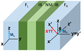
Figure 1. Schematic of a double-barrier MTJ of the form F/IB/NM/IB/F, where F, IB and NM denote the ferromagnet, insulating barrier and nonmagnetic metal spacer, respectively. ML and MR denote the magnetizations of the two ferromagnetic electrodes.
Download figure:
Standard image High-resolution imageThe TSTT effect exerted per unit square of the FR layer [31] can be expressed as  , where
  is the x' -component of the spin current density. The
  component of the spin current density can be expressed as
![$\frac{\text{i}\hslash}{2m}\left[\left(\frac{\partial}{\partial y}{{\Psi}^{+}}(y)\right){{\sigma}_{\alpha}} \Psi (y)-{{\Psi}^{+}}(y){{\sigma}_{\alpha}} \Psi (y)\right]$](https://content.cld.iop.org/journals/0953-8984/29/2/025806/revision1/cmaa44b5ieqn006.gif) , where
, where ![$ \Psi =\left[\begin{array}{c} {{\psi}_{\uparrow}}(y) \\ {{\psi}_{\downarrow}}(y) \end{array}\right]$](https://content.cld.iop.org/journals/0953-8984/29/2/025806/revision1/cmaa44b5ieqn007.gif) and
and  represent the Pauli matrices [32]. The charge current density can now be calculated based on the formulation above as follows:
This study uses a simple one-band model [2, 33, 34] to compute thermal spin transfer torque in the double-barrier MTJ of the form F/IB/NM/IB/F, where the ferromagnet layer and insulating barrier are assumed to be Fe and MgO, respectively. In our previous study [26], the same model is also used to calculate the traditional current-induced spin transfer torque in the same MTJ. By setting dNM = 0 nm in the model, the results for a traditional single-barrier MTJ of the form F/IB/F can be obtained. The theoretical studies for the traditional single-barrier MTJ have been investigated in [31]. Our results for dNM = 0 nm are quite consistent with the results in this reference. Moreover, Wilczyński et al have found that their results for in-plane torque in systems with semi-infinite electrodes roughly coincide with those presented in [30]. Most importantly, the theoretical predictions in this reference agree well with the experimental measurements [6].
The governing equation for the wave function of spin-up and spin down electrons can be expressed as  , where
  and U are the molecular field [33] and potential barrier height, respectively. The wave functions in layer j of the MTJ can be expressed as
  , where
  and
and  are the amplitudes of the waves in the +y and −y directions, respectively. The superscript,
  or (
or ( ), denotes spin-up and spin-down electrons. The wave function and its derivative must be continuous at all system boundaries. Owing to the quantization axis change between the right-hand side insulating barrier and the ferromagnet, the boundary conditions are expressed as
  and
and  . Based on these boundary conditions and the expression the wave functions, the transfer matrix of the whole system can be expressed as
  , where
  ,
,  and
and  . The submatrix
  in
in  is defined as
  . O here refers to a 2 × 2 null matrix. The submatrices
  and
and  are defined as
  and
and  , respectively. The submatrix
  in R is defined as
 . The amplitudes of the electron wave function and current density can be numerically solved based on the transfer matrix method. The total spin current density [35] can then be expressed as
where TL(R) is the temperature at the left (right) electrode. To compute the charge current density, the quantity  should be replaced by j in equation (1). The parameters used for the ferromagnet are Fermi energy level of EF = 2.62 eV and a spin-splitting energy of
  = 1.96 eV, which are the parameters for iron that have been widely used in several analytical model studies of MTJ [31]. The parameter for barrier is the barrier height U = 2.7 eV. This value of barrier height is adopted from [34]. Studies also have shown that the barrier height at MgO/metal interface can be tuned by a modification of the oxygen partial pressure or the sample temperature [36]. The parameter for non-magnetic layer is U = 0 eV, which is adopted from [37]. This parameter can be related to real materials such copper.
3. Results and discussion
Once the material for the double-barrier MTJ is decided, the most important parameters that can be adjusted to optimize the design are the thicknesses of the barrier layer and nonmagnetic metal spacer. Figure 2 plots the magnitude of TSTT and the charge current density as a function of the barrier thickness for three different thicknesses of the nonmagnetic metal spacer, dNM = 0 nm, dNM = 0.44 nm, and dNM = 0.8 nm. The temperature at the left and right electrodes are 300 K and 10 K, respectively. For dNM = 0 nm, the MTJ turns in to a traditional single barrier MTJ. As can be seen in the figure, the largest TSTT can be achieved with a barrier thickness of approximately 0.3 nm, which is marked by a triangle. The corresponding charge current density is approximately 0.07 A µm−2. For dNM = 0.44 nm and dNM = 0.8 nm, the MTJ turns out to be a double barrier structure. It is found that the largest TSTT for the MTJ with dNM = 0.44 nm (marked by a circle) is larger than the largest TSTT for the MTJ with dNM = 0.8 nm (marked a square). For increasing barrier thicknesses, the TSTT gradually increases to a peak value, following which it reduces and approaches to zero for thicker barriers. A similar phenomenon has been observed in the single barrier MTJ [34]. Most importantly, the TSTT magnitude for the proposed double barrier MTJ can be can be approximately twice as much as that of the traditional single barrier MTJ [34]. In addition, the difference between the temperatures of the two electrodes also leads to a finite charge current density flowing through the junction. The charge current density of the double-barrier MTJ is also larger than that of the traditional single-barrier MTJ. Such a phenomenon has been proposed before for improving the traditional STT using a double tunnel junction [26, 38]. The enhanced TSTT may also be attributed to the quantum well states that are formed in the nonmagnetic metal spacer and the resonant tunneling mechanism that exists throughout the system [37].
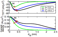
Figure 2. (a) TSTT and (b) charge current density as a function of the thickness of the barrier layer (dIB), for three different nonmagnetic metal layer thicknesses (dNM). The other parameters used for the simulation are Fermi energy, EF = 2.62 eV; height of the insulating barrier, UI = 2.7 eV; and angle between the magnetization of the two ferromagnetic electrodes,  . The temperature at the left and right electrodes are 300 K and 10 K, respectively. The triangle, circle, and square symbols denote the location of the largest TSTT for dNM = 0 nm, dNM = 0.44 nm, and dNM = 0.8 nm, respectively.
Download figure:
Standard image High-resolution imageThe nonmagnetic metal spacer in the double barrier structure acts as a resonant cavity. Therefore, the design of a proper thickness for the nonmagnetic metal spacer is critical. Therefore, TSTT and the charge current density as a function of the thickness of nonmagnetic metal spacer are plotted for three different barrier thicknesses, as shown in figure 3.

Figure 3. (a) TSTT and (b) charge current density as a function of the thickness of the nonmagnetic metal spacer (dNM), for three different insulating barrier thicknesses. The parameters are the same as those used in figure 2. The arrows denote the first two local peaks of the TSTT for the three different barrier thicknesses. For dNM = 0 nm, the structure becomes a traditional single-barrier MTJ. The circle, triangle, and square symbols denote the magnitude of (a) TSTT and (b) current of the single barrier MTJ for dIB = 0.2 nm, dIB = 0.42 nm, and dIB = 0.8 nm, respectively. Transmission spectra of the (c) single-barrier and (d) double-barrier MTJ at dIB = 0.42 nm.
Download figure:
Standard image High-resolution imageIt is observed that TSTT oscillates as the thickness of the nonmagnetic metal spacer increases from 0 nm to 1 nm, as shown in figure 3(a). For the three different barrier thicknesses, the locations of the peak for the TSTT are quite close to each other. However, the magnitudes of these peaks are different. The peak value of TSTT for dIB = 0.42 nm is larger than that for dIB = 0.2 nm and 0.8 nm. In addition, the current density also oscillates as the thickness of the nonmagnetic metal spacer increases from 0 nm to 1 nm, as shown in figure 3(b). Similar oscillating phenomena have been observed for the TMR ratio and the traditional STT effect in double barrier MTJ devices [26, 37]. This oscillating effect may also be related to the quantum well states that are formed in the nonmagnetic metal spacer [37]. The locations of the peak for TSTT and the charge current density are shifted for the three different barrier thicknesses. However, these peaks are quite close to each other. The magnitude of TSTT and the charge current density varies to a great extent for different nonmagnetic metal spacer thicknesses, whereas the barrier thicknesses do not have a very strong influence on the peak value for both TSTT and charge current density. For dNM = 0 nm, the structure of the MTJ becomes a traditional single barrier structure. Again, it is found that both TSTT and the charge current density of the double barrier MTJ can be larger than that of the traditional single barrier MTJ. To show that the TSTT enhancement can be related to the quantum-well states formed in the nonmagnetic metallic spacer and the resonant tunneling mechanism through heterojunction, the transmission spectra for both single-barrier (dNM = 0 nm) and double-barrier MTJ are investigated as shown in the figure below. In contrast to single-barrier MTJ, resonant tunneling is observed at  0.75 eV in the double-barrier MTJ.
In figures 2 and 3, the temperature difference  and the exchange splitting energy of the left and right electrodes is kept fixed. In order to understand the effect of the change of temperature gradient and exchange splitting energy on the system, the TSTT and charge current density as a function of temperature gradient are plotted for three different exchange splitting energy, as shown in figure 4. In order to achieve higher TSTT, the thicknesses of the barrier and nonmagnetic metal layer are chosen to be 0.42 nm and 0.44 nm, respectively, based on the results in figures 2 and 3. It is found that the absolute value of the TSTT monotonically increases for increasing temperature gradient, as shown in figure 4(a). For larger exchange splitting energies, the magnitude of TSTT increases more rapidly. As for the charge current density, the phenomenon is quite similar to that of the TSTT. The absolute value of the magnitude of the charge current density also monotonically increases for increasing temperature gradient. For larger exchange splitting energy, the magnitude of the charge current density also increases more rapidly. In contrast to the traditional STT with asymmetric bias dependence, the magnitude of the in-plane torque and the charge current density does not depend on the sign of
  here. A change of sign of
  only results in a change of direction of the TSTT and the direction of current flow.
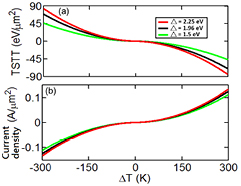
Figure 4. (a) The TSTT and (b) the charge current density for double barrier MTJ as a function of the temperature difference of the left and right electrodes, with three different exchange splitting energies,  = 1.5 eV,
  = 1.96 eV, and
  = 2.25 eV. The thickness of the barrier layer and the NM layer are fixed to be 0.42 nm and 0.44 nm, respectively. The values for the other parameters of the junction are the same as those listed in the caption of figure 2.
Download figure:
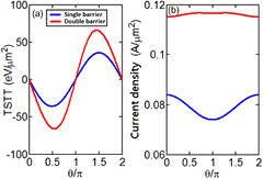
Standard image High-resolution imageNext, we study the effect of the angle  between the magnetic moments of the electrodes on the STT and charge current density for the double barrier MTJ, as shown in figure 5. The case for single barrier MTJ is also plotted for comparison. For the STT of the single barrier MTJ, as one might expect, the torque is zero in the collinear configuration and reaches a maximum absolute value for
  and
and  , i.e. when the magnetic moments of the electrodes are oriented perpendicularly [31]. For the case of the double barrier MTJ, the features of the STT are quite similar to the single barrier MTJ, except that the magnitude of the TSTT is different. The peak value of the TSTT for the double barrier MTJ is approximately twice as much as that of the traditional single barrier structure. For the same temperature between the two electrodes, it is found that the charge current density for the double barrier MTJ is also twice as much as that of the traditional single barrier structure.
Figure 5. (a) TSTT and (b) charge current density as a function of  for single barrier and double barrier MTJs. The thickness of the barrier layer and the nonmagnetic metal spacer are again fixed at 0.42 nm and 0.44 nm, respectively. The values for all the other parameters are the same as those listed in the caption of figure 2.
Download figure:
Standard image High-resolution image
4. Conclusion
In conclusion, enhancement of the TSTT in double barrier MTJs with a nonmagnetic metal spacer is proposed. Interestingly, the magnitude of STT and the charge current density in this double barrier structure can be twice as much as that of the traditional single-barrier MTJs, if the thickness of the nonmagnetic metal spacer is optimally designed. This improvement in the TSTT can be related to the quantum-well states that are formed in the nonmagnetic metal spacer and the resonant tunneling mechanism through the whole material stack configuration system.
Acknowledgments
The authors acknowledge the support provided by the Ministry of Science and Technology of Taiwan, under grant numbers MOST 105-3113-E-002-001 and MOST 105-2221-E-002-136.