
Abstract
Starting from recent JET experimental results that show a significant reduction of ion stiffness in the plasma core region due to plasma rotation in the presence of low magnetic shear, an experiment was carried out at JET in order to separate the role of rotation and rotation gradient in mitigating the ion stiffness level. Enhanced toroidal field ripple (up to 1.5%) and external resonant magnetic fields are the two mechanisms used to try and decouple the rotation value from its gradient. In addition, shots with reversed toroidal field and plasma current, yielding counter-current neutral beam injection, were compared with standard co-injection cases. These tools also allowed varying the rotation independently of the injected power. Shots with high rotation gradient are found to maintain their low stiffness level even when the absolute value of the rotation was significantly reduced. Conversely, high but flat rotation yields much less peaked ion temperature profiles than a peaked rotation profile with lower values. This behaviour suggests the rotation gradient as the main player in reducing the ion stiffness level. In addition, it is found that inverting the rotation gradient sign does not suppress its effect on ion stiffness.
Export citation and abstract BibTeX RIS
1. Introduction
Theoretical models describe turbulent ion heat transport as mainly driven by ion temperature gradient (ITG) modes. They become unstable above a threshold value of the inverse ion temperature (Ti) gradient length
 , where R is the tokamak major radius and
 ) and lead the ion heat flux to increase strongly with
 , thereby preventing attaining
values much higher than the threshold value. This behaviour can be described by the stiffness level, a parameter that quantifies the tendency of the Ti profiles to remain tied to the threshold independently of the amount of heating power applied. The description of turbulent ion heat transport in terms of threshold and stiffness has been proposed theoretically [1–3] and supported by experimental observations [4–8]. Knowing the dependence of threshold and stiffness on plasma physical quantities is then relevant to investigate how the ion heat transport and then the plasma performances can be acted upon.
, thereby preventing attaining
values much higher than the threshold value. This behaviour can be described by the stiffness level, a parameter that quantifies the tendency of the Ti profiles to remain tied to the threshold independently of the amount of heating power applied. The description of turbulent ion heat transport in terms of threshold and stiffness has been proposed theoretically [1–3] and supported by experimental observations [4–8]. Knowing the dependence of threshold and stiffness on plasma physical quantities is then relevant to investigate how the ion heat transport and then the plasma performances can be acted upon.
Parametric studies about the role of Te/Ti, q profile, magnetic shear and toroidal rotation (Ω) have been carried out through experimental investigations in the JET tokamak [5]. In particular, the toroidal rotation in the presence of low magnetic shear, as described in [4, 7], has been found to have a significant effect of reduction of ion stiffness, yielding much higher
than due to the mere ωE×B threshold up-shift [9]. However, in the experiments reported in [7], the values of rotation and of its gradient were correlated, so it was not clear if the effect of reducing the stiffness had to be ascribed to Ω or ∇Ω.
Starting from the results obtained by the previous investigation reported in [4, 5, 7], where the relation of causality between plasma rotation and ion stiffness has been widely studied and deduced, an experiment was then carried out in JET in order to decouple the effect of Ω and ∇Ω. Two methods of plasma rotation braking have been used. The first one is based on enhancing the toroidal field (BT) ripple. In tokamaks the BT ripple, a toroidally periodic variation of the external BT, exists because of the finite number of BT coils. JET has the possibility of varying the ripple amplitude [10]. This was found to have significant effects on the plasma rotation [11], since a large BT ripple by breaking the axi-symmetry of the magnetic field induces enhanced non-ambipolar particle losses. This takes place particularly in the external region of the plasma and leads to an edge counter-current torque that brakes the plasma rotation. The second method consists in the application of low n external magnetic perturbation fields produced by the set of four external error field correction coils (EFCC) of JET [12]. Also in this case previous experiments showed strong effects on the plasma rotation due to breaking the toroidal symmetry and slowing down the plasma rotation by neoclassical toroidal viscosity (NTV) [13]. Applying these techniques, in addition to providing to a certain extent a decoupling of Ω and ∇Ω, allows in addition to perform discharges with different rotations but constant total injected power, allowing to assess the effect of rotation on stiffness when rotation is decoupled from power. In [7], instead, lower values of rotation were obtained using less neutral beam injection (NBI) power, apart from the case of reverse BT shots with counter-NBI, which is also a remarkable method of decoupling rotation from its gradient and also from power, and will also be considered in this paper.
The experiment description and the obtained results are presented in section 2. From these, the conclusion is derived that the ion stiffness reduction has to be ascribed to rotation gradient rather than to rotation. In section 3, we show in addition that also a rotation gradient with reversed sign (hollow rotation) also acts mitigating stiffness. In section 4 the conclusions are reported.
2. Rotation braking experiment
2.1. Experimental set-up
At JET it is possible to vary the BT ripple amplitude δ, defined as
 . For standard JET operations, which are carried out with a set of 32 BT coils carrying equal current, δ = 0.08%. Because odd and even coils are powered independently, the imbalance current between the two coils sets can be changed increasing the BT ripple up to δ = 3%. These values refer to the maximum BT ripple values in the plasma, taken at the outer mid-plane at R = 3.8 m and z = 0. Energetic particles can be toroidally trapped in the magnetic ripple and then drifted out of the plasma because of the field curvature. In addition, the trajectory of banana-orbits trapped particles can be altered by BT ripple, which causes them to drift radially outwards. In the presence of a large BT ripple other ion losses, possibly those of thermal ions, may be involved [18]. The friction between circulating particles and those locally trapped in BT ripple tends to reduce the toroidal rotation [19]. However, the dominant effect on the toroidal rotation is given by the outward lost ion flow, which induces a radial return current j in order to preserve neutrality. The resulting j × B torque is always in the counter-current direction. It leads to a significant reduction of both the edge and core rotation, but affects less the core spatial gradient [10, 11, 20, 21].
Also the external perturbation fields applied through the EFCC system influence the JET plasma rotation and rotation shear. The EFCC set consists of four square shaped coils mounted outside the vacuum vessel. Depending on the wiring of the EFCCs either n = 1 or n = 2 fields can be created. Low n perturbation fields break the toroidal symmetry. The plasma flows then along distorted flux surfaces and it is subjected to a drag toroidal force, due to the NTV, that influences the plasma rotation and its gradient [13, 22]. A reduction in toroidal rotation at different radii by the same factor (gradvφ/vφ = constant) is observed over the whole plasma core and stronger rotation braking is found near the edge pedestal [12, 23, 24].
The presence of a 3D distortion of the magnetic field may yield to the non-axisymmetry of ion temperature and rotation profiles, thus affecting the determination of ion thermal transport within a 1D approach [25]. However, studies of these effects are out of the scope of this investigation, which concerns core transport, i.e. in a region where the 3D field perturbations are very small, particularly in the case of enhanced BT ripple [17, 25], which turned out to be the most useful for these studies. In other words we can correctly study in a core region without 3D field perturbations the effects of rotation profiles changes driven by edge 3D perturbations.
The rotation braking experiments are performed in H-mode plasmas at BT = 2 T for shots with varying BT ripple and at BT = 1.85 T for shots with EFCC, with Ip = 1.5 MA, low triangularity, q95 = ∼5, ne0 ∼ 3 × 10¹⁹ m−3, 0.9 < Te/Ti < 1.1. Ion cyclotron resonance heating (ICRH) and NBI are used as heating systems. Keeping the total injected power fixed, the ICRH and NBI powers are varied to obtain a sufficiently wide ion heat flux scan and to observe different rotation profiles. In order to perform two basic steps of core ion heat flux scan, ICRH (0–2 MW) is applied varying deposition between on- and off-axis at ρtor ∼ 0.7. It is used in a (H)-D scheme (33 MHz on-axis, 42 MHz off-axis) with nH/ne ∼ 8% and 20–30% of the ICRH core power delivered to thermal ions. ICRH power deposition profiles are obtained by the PION code [14] calculations, for NBI power deposition a first analysis is carried out using the code PENCIL [15]. This code is computationally faster; however, it omits the ion orbit physics and does not take into account the ripple effect. Then three representative discharges (one with enhanced BT ripple, one with standard ripple and one with the application of EFCCs fields) are reprocessed with ASCOT [16], an orbit-following Monte Carlo code that includes in the calculations fast ion losses due to the enhanced BT ripple [17]. The ripple effect is found negligible for ρtor < 0.4, allowing to calculate the NBI heat flux in the core—which is what is required for the stiffness study—without any ripple correction. However, the NBI ion heat flux obtained by ASCOT is found 20% higher than that provided by the PENCIL code, with the same multiplication factor between the two code calculations for all the discharges. Since ASCOT features a more refined treatment of NBI deposition, the PENCIL NBI ion heat fluxes obtained for all shots are then corrected by this multiplication factor, in order to minimize the systematic error. Different NBI powers from 4 to 7 MW are injected in the plasma to produce a large spectrum of high rotation profiles at standard ripple. For each case, enhanced BT ripple or EFCCs are then applied.
2.2. Data analysis and experimental results
In figure 1 the rotation as a function of the rotation gradient is shown for the investigated shots. Triangles refer to standard BT ripple (0.08%) discharges, squares and diamonds to enhanced BT ripple discharges (respectively 1% and 1.5%) and EFCCs shots are indicated by circles. The values of rotation, measured by means of charge exchange recombination spectroscopy (CXRS), are averaged in time over a stationary interval and taken at the radial position ρtor = 0.25: it encloses the on-axis power but not the off-axis one, giving the maximum ion heat flux scan, useful in order to investigate the stiffness level of the analysed shots. The gradient of rotation is calculated from the channels 2–5 of the CX diagnostic, with centre at ρtor = 0.25.
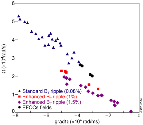
Figure 1. Toroidal rotation as a function of toroidal rotation gradient for standard BT ripple (triangles), enhanced BT ripple (squares 1% and diamonds 1.5%) and EFCCs (circles) shots. Rotation and its gradient are taken at ρtor = 0.25.
Download figure:
Standard imageDischarges without methods of rotation braking present higher values of rotation and rotation gradient with respect to discharges in which enhanced BT ripple or EFCCs are applied. The enhanced BT ripple shots reach higher values of rotation gradient relative to the rotation value if compared with the trend proper for the standard BT discharges. Shots where EFCCs are switched on are in line with the standard discharge trend. Only enhanced BT ripple seems to be able to decouple rotation and rotation gradient for discharges characterized by the above-reported physical values and with the above-described heating powers. It is then possible to investigate the role that rotation and rotation gradient have separately on the ion stiffness.
To this aim, a first analysis is carried out by comparing Ti profiles of plasmas characterized by similar gradients of rotation and different rotation values, as in the example shown in figure 2. It refers to one of the shots with enhanced BT ripple characterized by reduced rotation with respect to rotation gradient and a standard BT ripple shot with similar power level and ion heat deposition and plasma parameters except for the ripple level, with a similar rotation gradient but larger rotation value all along the plasma radius. As shown in figure 2(b), the Ti profiles for the two shots and their gradients are identical, even if the values of rotation differ significantly. This is verified not only around the radial position ρtor = 0.25 but along all the temperature profiles (the perfect match of the two profiles has to be considered a coincidence).
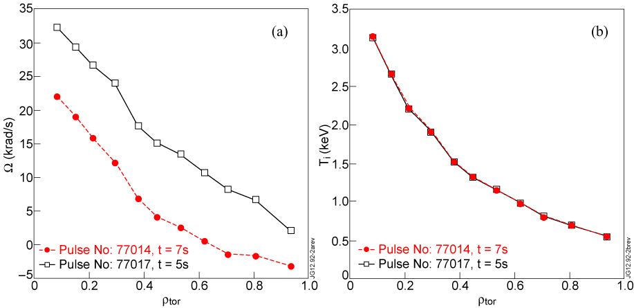
Figure 2. Toroidal rotation (a), ion temperature (b) profiles of two shots with standard (77017, solid line with squares) and enhanced (77014, dashed line with circles) BT ripple. In the neighbourhoods of ρtor = 0.25 the two shots are characterized by similar rotation gradient but significantly different rotation value. The profiles are taken at the times indicated in the legend of the graphs.
Download figure:
Standard imageThe method of enhancing the BT ripple or applying the EFCCs fields does not allow us to obtain discharges with a reduced rotation gradient with respect to the rotation value. Therefore, limiting the analysis to shots of this braking experiment, a comparison between plasmas with similar values of rotation and different rotation gradients would not be feasible. However, using as auxiliary heating counter-NBI in reverse BT and Ip configuration is known to produce plasmas with flatter toroidal rotation with respect to the corresponding co-NBI plasmas because of off-axis torque deposition [7, 26]. A discharge that belongs to such a set of experiments (the pulse number 59630 at 14 s), characterized by similar parameters and standard BT ripple and heated by counter-NBI with a power level nearly equal to the shots of the rotation braking experiments, was then taken into account for the comparison. In figure 3 it is compared with an enhanced ripple discharge, which has similar values of rotation and higher rotation gradient around the radial position ρtor = 0.25 (figure 3(a)). The associated Ti profiles shown in figure 3(b) are then very different, indicating that the similar absolute value of Ω does not lead to similar core Ti peaking if ∇Ω is very different. As we can see in figure 3(c), although the power deposition profiles are different for the two discharges (in the case of counter-NBI the distribution of power to ions and electrons is less peaked in the central part of the plasma), inside the considered radius ρtor = 0.25 the counter-NBI shot does not have significantly less ion power than the co-NBI shot (3.8 MW against 4.1, see also [7], where an exhaustive analysis about the comparison between co- and counter-NBI plasmas is reported). In contrast, in terms of normalized ion heat flux, one can see in figure 4 that the counter-NBI shot is the one with the highest normalized ion heat flux.
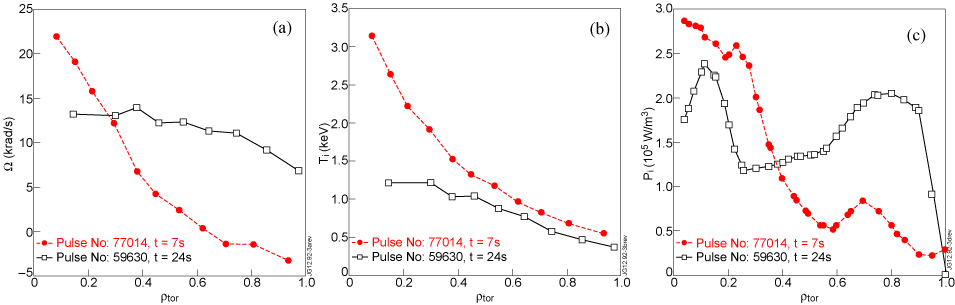
Figure 3. Toroidal rotation (a), relative ion temperature (b) and ion power deposition (c) profiles of one shot with enhanced BT ripple and co-NBI (77014, dashed line with circles) and one shot with standard BT ripple and counter-NBI (59630, solid line with squares). At ρtor = 0.25 shot 77014 is characterized by a value of rotation similar to the one of shot 59630 but very different gradient. The profiles are taken at the times indicated in the legend of the graphs.
Download figure:
Standard image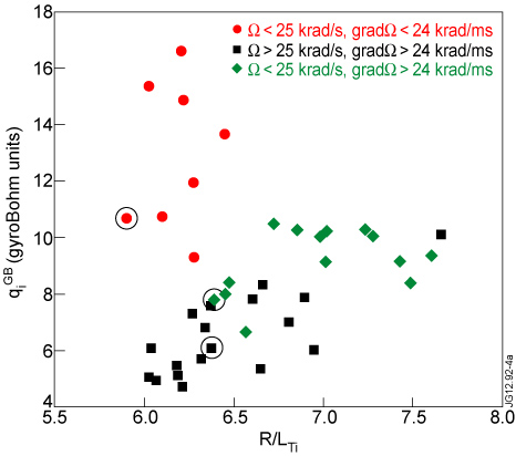
Figure 4. Gyro-Bohm normalized ion heat flux qi as a function of
at ρtor = 0.25. Points are grouped with respect to the values that ∇Ω and Ω reach at ρtor = 0.25. Circled points refer to the shots treated in the first analysis in which temperature and rotation profiles are compared. In particular, 77014 is indicated by a square point, 77017 by a diamond and 59630 by a circle.
Download figure:
Standard imageWe conclude that from the simple comparison of experimental profiles, the Ti profile peaking seems related more to ∇Ω than to Ω.
One important limitation of simple profile analysis is that it cannot determine if larger ∇Ti are due to higher ion threshold values or to lower ion stiffness values. In order to clarify this point a second type of analysis is carried out, taking into account the value of the ion heat flux in all the discharges. Although this point was already clarified in [7], a further confirmation was searched in this set of discharges, where in addition we try to separate the different roles of ∇Ω and Ω.
The ion heat fluxes qi at the radial position ρtor = 0.25 are plotted in figure 4 as functions of the logarithmic gradient of the ion temperature
calculated at the same radius. As in [7], qi is calculated by spatial integration of ion power density profiles and by determining the collisional electron–ion transfer by means of interpretative transport simulations. The heat flux is expressed in gyro-Bohm units. Gyro-Bohm scaling is predicted to characterize plasmas dominated by anomalous transport [2]. In the following formula the gyro-Bohm normalization is made explicit

where ρi is the ion Larmor radius, R is the major radius of the JET tokamak,
 , ni is the ion density and Ti is the ion temperature.
is obtained by an exponential best-fit over 4 CX channels, with centre in ρtor = 0.25 and averaged in time over a stationary interval. The ITG is calculated with respect to the flux surface minor radius, ρ = (Rout − Rin)/2, where Rout (Rin) is the outer (inner) boundary of the flux surface on the magnetic axis plane. In figure 4 circles and squares represent pulses characterized by coupled rotation and rotation gradient values: circles are low rotation shots with ∇Ω < 24 krad ms−1 and Ω < 25 krad s−1; squares are high rotation shots with ∇Ω > 24 krad ms−1 and Ω > 25 krad s−1. The two sets of points form two distinct curves: the one formed by circular points is characterized by high stiffness level, and the one formed by square points is characterized by low stiffness. We can see that the behaviour shown by the experimental results described in [7] is confirmed. Points with decoupled rotation gradient and rotation are shown with diamonds. They are characterized by ∇Ω > 24 krad m s−1 and Ω < 25 krad s−1. These points sit well in the low stiffness curve, although they are characterized by low rotation values. Then we can conclude that it is the rotation gradient that matters in reducing the ion stiffness level, and not the absolute value of rotation. With respect to the results represented in [7] in this experiment the excursion of
, ni is the ion density and Ti is the ion temperature.
is obtained by an exponential best-fit over 4 CX channels, with centre in ρtor = 0.25 and averaged in time over a stationary interval. The ITG is calculated with respect to the flux surface minor radius, ρ = (Rout − Rin)/2, where Rout (Rin) is the outer (inner) boundary of the flux surface on the magnetic axis plane. In figure 4 circles and squares represent pulses characterized by coupled rotation and rotation gradient values: circles are low rotation shots with ∇Ω < 24 krad ms−1 and Ω < 25 krad s−1; squares are high rotation shots with ∇Ω > 24 krad ms−1 and Ω > 25 krad s−1. The two sets of points form two distinct curves: the one formed by circular points is characterized by high stiffness level, and the one formed by square points is characterized by low stiffness. We can see that the behaviour shown by the experimental results described in [7] is confirmed. Points with decoupled rotation gradient and rotation are shown with diamonds. They are characterized by ∇Ω > 24 krad m s−1 and Ω < 25 krad s−1. These points sit well in the low stiffness curve, although they are characterized by low rotation values. Then we can conclude that it is the rotation gradient that matters in reducing the ion stiffness level, and not the absolute value of rotation. With respect to the results represented in [7] in this experiment the excursion of
 and
is limited by the impossibility of using 3He ion heating due to the absence of suitable ICRH frequencies at the low BT values needed for enhanced ripple. Therefore the highest values of
are not achievable in the enhanced ripple discharges. Also very low qi values, which would be relevant for the determination of the ion threshold, are not feasible because they require off-axis ICRH, which is too risky under conditions of high BT ripple due to losses of highly energetic ICRH ions in the plasma periphery.
and
is limited by the impossibility of using 3He ion heating due to the absence of suitable ICRH frequencies at the low BT values needed for enhanced ripple. Therefore the highest values of
are not achievable in the enhanced ripple discharges. Also very low qi values, which would be relevant for the determination of the ion threshold, are not feasible because they require off-axis ICRH, which is too risky under conditions of high BT ripple due to losses of highly energetic ICRH ions in the plasma periphery.
3. RF driven hollow rotation experiment
The discharges of the above-described experiment and those belonging to the experiments reported in [7] are characterized by profiles of plasma toroidal rotation that are monotonic and peaked in the central part of the plasma, i.e. with negative rotation gradient. In order to understand if the sign of the rotation gradient can play a role in influencing the ion stiffness, and then the ion temperature profiles, discharges belonging to a different experiment also based on the use of (3He)-D ICRH are analysed. Some experimental observations on JET and C-MOD have shown that the toroidal rotation is sensitive to the 3He concentration [27–29]. In particular, in some range of concentrations ICRF mode conversion is found to drive toroidal flow in the co-Ip direction in C-MOD whilst in JET it gives origin to hollow rotation profiles, leading to suppose the existence of a torque in the counter-Ip direction [30]. A selection of discharges that exhibit hollow rotation profiles in the presence of (3He)-D ICRH heating are analysed and compared with similar discharges in which the rotation profile was not hollow but flat.
3.1. Experimental set-up
The analysis refers to L-mode plasmas, characterized by BT = 3.3 T, IP = 1.8 MA, ne0 = 3.5 × 10¹⁹ m−3. The heating is provided by RF power, with a frequency of 33 MHz and a power of 7 MW. The power deposition is varied from dominant electron in 3% (H)-D minority to dominant ion in 4–8% (3He)-D to dominant electron in 20% (3He)-D where mode conversion takes place. Other discharges characterized by the parameters reported above but NBI heated are included in our analysis, in order to have high negative rotation gradient plasmas to compare with the positive ones obtained from hollow rotation profiles. The power deposition and then the ion heat flux are derived using the codes PION and ASCOT. Physical quantities are measured and obtained as described in the previous section.
3.2. Data analysis and experimental results
In figure 5, rotation profiles and corresponding Ti profiles of one pulse at two different times (and different 3He concentration) are shown. The rotation profile is hollow for ρtor < 0.3 at t = 7.5 s, with rotation values still in the co-IP direction. The rotation becomes flat at t = 11.2 s. As shown in figure 5(b), we find different Ti profiles in the plasma region within ρtor = 0.3. In this zone higher values of the Ti gradient are observed for the case of hollow rotation where the rotation gradient is rather high and positive, even if the rotation value is lower with respect to the case of flat rotation.
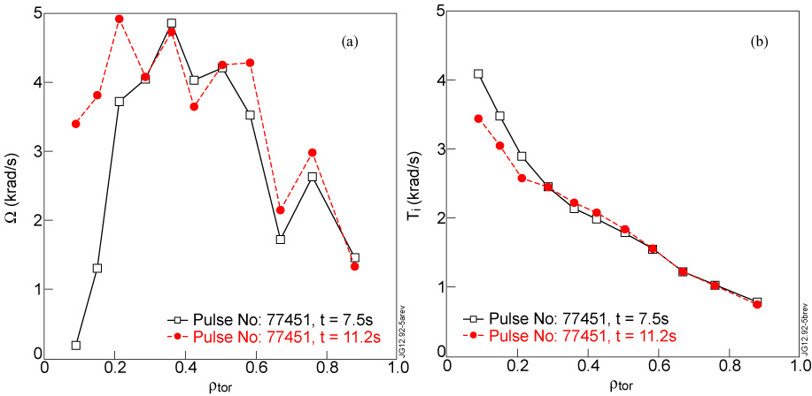
Figure 5. Toroidal rotation profiles (a) and relative ion temperature profiles (b) of shot 77451 at 7.5 s and 11.2 s. For ρtor < 0.3 the shot number 77451 at 7.5 s (solid line with squares) is characterized by hollow rotation, instead at 11.2 s (dashed line with circles) the rotation is flat. In this region the Ti reaches higher values in the case with hollow rotation.
Download figure:
Standard imageIn order to compare properly the different shots, they are plotted again in the
 versus
plot in figure 6. Here circles, characterized by low Ω and ∇Ω, belong to the high stiffness curve, triangles have medium Ω and ∇Ω and sit in the medium stiffness curve and squares, which are characterized by high Ω and ∇Ω, form the low stiffness curve, consistently with the graph of figure 4. The points obtained from the profiles shown in figure 5 are encircled. The one with flat rotation has a low value of Ω and ∇Ω, so it is shown with a circle. It is found to sit among the other circles and clearly belongs to high stiffness family. The point calculated at the time in which the rotation is hollow is represented by a diamond and is characterized by medium positive ∇Ω and low Ω. The normalized ion heat flux in the hollow rotation cases is comparable to that of other flat cases, whilst the ratio Te/Ti is a bit higher in the case of hollow rotation, which should even decrease
in this case due to a threshold decrease [5]. Instead, a systematic high value of
is seen in hollow cases, which we ascribe to reduced stiffness due to the (positive) rotation gradient. We can see that the points with medium rotation gradient belong to the medium stiffness curve independently of the sign of the gradient. It is then the absolute value of the rotation gradient that influences the ion stiffness level, no matter what sign it has.
versus
plot in figure 6. Here circles, characterized by low Ω and ∇Ω, belong to the high stiffness curve, triangles have medium Ω and ∇Ω and sit in the medium stiffness curve and squares, which are characterized by high Ω and ∇Ω, form the low stiffness curve, consistently with the graph of figure 4. The points obtained from the profiles shown in figure 5 are encircled. The one with flat rotation has a low value of Ω and ∇Ω, so it is shown with a circle. It is found to sit among the other circles and clearly belongs to high stiffness family. The point calculated at the time in which the rotation is hollow is represented by a diamond and is characterized by medium positive ∇Ω and low Ω. The normalized ion heat flux in the hollow rotation cases is comparable to that of other flat cases, whilst the ratio Te/Ti is a bit higher in the case of hollow rotation, which should even decrease
in this case due to a threshold decrease [5]. Instead, a systematic high value of
is seen in hollow cases, which we ascribe to reduced stiffness due to the (positive) rotation gradient. We can see that the points with medium rotation gradient belong to the medium stiffness curve independently of the sign of the gradient. It is then the absolute value of the rotation gradient that influences the ion stiffness level, no matter what sign it has.
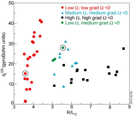
Figure 6. Gyro-Bohm normalized ion heat flux qi as a function of
at ρtor = 0.25. Points are grouped with respect to the values that ∇Ω and Ω reach at ρtor = 0.25.
Download figure:
Standard image4. Conclusions
Experiments are presented where the correlation between the absolute value of the rotation and its gradient is broken by enhancing the BT ripple, which has effect on the rotation, lowering its value, while it acts less strongly on the rotation gradient. The use of magnetic perturbations by EFCCs is as effective as BT ripple in breaking the correlation.
Comparing pairs of discharges characterized by similar rotation value and different rotation gradients and pairs of discharges with similar rotation gradient and different rotation values, the observed behaviour of the ion temperature profiles indicates a dependence of the Ti peaking on the gradient of rotation rather than its value. In addition, the analysis of all the shots of the experiment in terms of the
versus
plot has shown net distinct curves of different ion stiffness for different gradients of rotation, confirming the previous results of [7] also under conditions where rotation is varied at similar constant total power. In particular, the discharges with decoupled low rotation and high rotation gradient sit well in the low stiffness curve. We can then conclude that the ion stiffness mitigation is due to the rotation gradient rather than to the rotation value.
By comparing discharges characterized by hollow rotation profiles with discharges with flat rotation profiles, the Ti profile peaking is observed to be higher in the case of hollow rotation, i.e. for a high positive rotation gradient, although the rotation value is lower than in the cases with flat rotation profile. Placing these discharges in the
versus
plot, in relation to discharges with lower values of rotation gradient and similar values but with opposite (negative) sign, results indicate that the level of ion stiffness depends on the absolute value of the rotation gradient, independently of its sign.
Acknowledgments
This work, supported by the European Communities under the contract of Association EURATOM/ENEA-CNR, was carried out within the framework of EFDA and under the JET-EFDA workprogramme [31]. The views and opinions expressed herein do not necessarily reflect those of the European Commission.
Euratom © 2013.