


1. Introduction
The first thermal ice drills used for glacier research, called hot points, were designed to produce boreholes without cores by melting ice (Talalay, Reference Talalay2020). These hot points have mainly been used for drilling in temperate glaciers where the borehole filled with fresh water stays open for days, which allows interruptions in the drilling and reaming process. To overcome problems with the meltwater refreezing in cold ice, in the middle of the 20th century, K. Philberth, an independent German physicist and engineer, invented the freezing-in probe to study the temperature distribution in an ice sheet (Philberth, Reference Philberth1962). This drill was able to move toward the glacier base while the melted water refroze behind the probe. The most outstanding characteristic of the probe was that the wires used to supply it with electrical power and receive signals from it paid out of the advancing probe and became fixed in the refreezing meltwater above it. This type of thermal drill is now often called a Philberth probe in honor of the inventor.
In the summer of 1968, the original Philberth probe reached an impressive depth of 1005 m at Station Jarl-Joset in Greenland (Philberth, Reference Philberth and Splettstoesser1976). Since then, at least ten different freezing-in probes have been developed for terrestrial and extraterrestrial ice investigations: CRREL pendulum probe (Aamot, Reference Aamot1968); Meltsonde probe of Australian Antarctic Division (Morton and Lightfoot, Reference Morton and Lightfoot1975); PICO thermal probe (Hansen and Kersten, Reference Hansen, Kersten, Holdsworth, Kuivinen and Rand1984); SIRG thermal probe (Kelty, Reference Kelty1995); Sonde under shelf ice (SUSI) (Tibcken and Dimmler, Reference Tibcken, Dimmler, Jokat and Oerter1997); Cryobot (Zimmerman and others, Reference Zimmerman, Bonitz and Feldman2001), VALKYRIE (Stone and others, Reference Stone, Hogan, Siegel, Lelievre and Flesher2014), SPINDLE (Stone and others, Reference Stone, Badescu and Zacny2018), Ice Diver (Winebrenner and others, Reference Winebrenner, Elam, Miller and Carpenter2013) and IceShuttle Teredo (Wirtz and Hildebrandt, Reference Wirtz and Hildebrandt2016). All these probes were designed for deep ice-sheet exploration. However, unfortunately, for various reasons, the maximal depth reached was not as great as that attained by the original Philberth probe. In most cases, the realized penetration depths were <100–200 m (only Ice Diver could penetrate to a depth of ~400 m).
One of the most important parts of the freezing-in downhole unit is the wire or cable reeled inside the probe and used for the transmission of power to the probe and telemetry from the built-in instrumentation. Because it freezes in the hole, the cable should work under low temperatures and extremely high ice hydrostatic compression. Usually, thermal and electromechanical ice drills suspended on a cable use steel wire armored cable. These cables have outer diameters in the range of 4.5–9 mm and weigh 0.09–0.35 kg m−1. The maximum bending radius (under tension) at the inner edge of bends is at least 12 times the outer diameter of the cable. Thus, they ultimately do not meet the requirements of freezing-in thermal ice probes.
The original Philberth probe contained two coils, one with insulated wire (with a wire diameter (WD) of 0.95 mm and insulation outer diameter (OD) of 1.26 mm) and another with bare wire (0.9 mm WD). A similar cabling system was utilized by Ice Diver. The CRREL, Meltsonde, PICO and SIRG thermal probes used a thin (1.8–2.3 mm OD) coaxial cable consisting of an insulated copper center conductor and a braided outer conductor. The power supply and signals of the SUSI probe were transferred through two insulated single copper wires with a 1.1 mm WD. The cabling systems of the Cryobot, SPINDLE and IceShuttle Teredo probes were not fully developed and tested.
The VALKYRIE probe uses a unique power source: a high-power laser transmits laser light to the vehicle via a glass fiber. To avoid power losses, the coiled fiber must have a large diameter. Hence, the probe must be equipped with a large thermal head, which will increase the power consumption. The performance of the frozen fiber is still unknown. After reaching a subglacial lake, the plan is for the probe to be able to turn 180° so that the thermal head is at the top of the vehicle. Then, a buoyancy engine or drop-mass release will activate and cause the vehicle to rise through the ice cap. The return mission doubles the fiber that needs to be stored inside the probe.
To investigate and sample the subglacial environment in Antarctica, a new type of Philberth probe, the RECoverable Autonomous Sonde (RECAS), was designed by the Polar Research Center, Jilin University, China (Talalay and others, Reference Talalay, Zagorodnov, Markov, Sysoev and Hong2014). A unique feature of the RECAS design is its ability to melt the borehole above the probe and move backward in an upward direction. The probe is equipped with two electrically heated melting tips: a solid one on the bottom and another with a central hole for the cable to pass through on the top of the probe (Li and others, Reference Li2020). A motor-driven double-wheel capstan controls the speed of the probe movement. Thus, the cable serves not only for the power/signal transmission but also as the load-carrying member. The first stage of the probe developing includes designing the prototype with an ability to reach the depth of ~500 m. Accounting surface arrangements, the total length of cable is specified to be 550 m. This paper reports the results of experimental investigations of different cable structures and materials. These made it possible to determine the design of a cable armored with synthetic fiber that yielded the most reliable performance.
2. Cable requirements
The selection of a particular cable technology involves a careful consideration of the specific electrical, mechanical and environmental requirements of the RECAS (Table 1). To minimize the probe weight and size, an outer diameter of ≤6.0–6.2 mm is specified for the cable, with a weight of ≤0.07–0.08 kg m−1. Based on a comparative analysis of alternative designs, the smallest outer diameter for the cable could be achieved with a coaxial structure design.
Table 1. Cable requirements and actual parameters
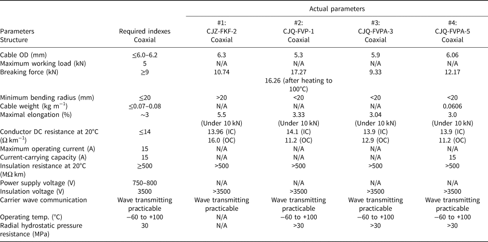
IC, inner conductor; OC, outer conductor; N/A, data are not available.
The weight of the RECAS probe is ~4.5 kN. During the return mission, the upper melting tip should press on the ice to melt it with an axial load of ~5 kN. Therefore, accounting for a safety factor of 1.8, the breaking force of the cable is set at >9 kN. The cable is coiled on the 40 mm diameter drum of the on-board winch. Thus, the minimal bending radius of the cable should be ≤20 mm. Because the cable passes through the capstan wheels and coils on the reel with a high load, it should maintain a regular round shape and cross-section under a large tensile force, and the friction between the outer cable layer and wheels should be sufficient to provide probe movement.
To minimize the size of the cable, the power to the probe is supplied at ~750 VAC and converted to the required voltage according to the component specifications. The maximal operating power of the RECAS probe is 11 kW. Thus, the cable must handle a maximum operating current of ~15 A. The cable insulation layer should withstand a voltage as high as 3500 VAC (2U 0 + 2000 V) (IEC, 60502-1, 2004).
When power is supplied from the surface to the probe in the borehole, there will be a definitive voltage drop in the conductors of the cable. In order to minimize the power loss, the resistance of the cable conductors should be as small as possible to meet the power transmission requirements. Taking into account the surface supply voltage and required working voltage of the probe, the DC resistance of the conductors is set at ≤14 Ω km−1 at 20°C. To effectively transmit a signal under this high-voltage power supply, the conductors should be able to transmit the waveforms of carrier wave communication.
Because it will be frozen in the hole, the cable should be capable of maintaining its properties under low temperatures down to −60°C and a high radial pressure from the refrozen ice of up to 30 MPa (the maximum planned penetrating depth of the probe is ~2500 m). Because it will be coiled on the in-board reel, the insulation and sheathing material of the cable should be capable of withstanding the heat generated by the resistance to the current flowing in the conductors, which could presumably raise the temperature to 100°C.
3. Testing methods
To ensure the safe use of the cable, multiple tests should be carried out for each batch of cable after processing. An application test should be performed with the probe to verify that the cable meets the actual working condition requirements while drilling.
3.1. Testing physical dimensions of cable
Before testing the mechanical and electrical properties, and the environmental suitability, the diameter of the conductors (copper wires), thickness of the insulation and sheathing layers, and outer diameter of the cable are tested using a KSM6/25/75 profile projector with a magnification of ≥10 times and measurement range of 0–75 ± 0.001 mm (Fig. 1a). A minimal length cable specimen is cut out perpendicular to the axial direction and placed on the specimen plate with the cross-section facing up. Different members of the cable are separated during testing. A reading microscope is used to inspect the cable cross-section (Fig. 1b). An image of each member is obtained and sent to a monitor, where the size of the member could be determined. The physical dimensions of the conductors, and the insulation and sheathing layers, have to meet the requirements of IEC 60811-1-1-1993, IEC 60228-2004 and IEC 60502-1-2004.
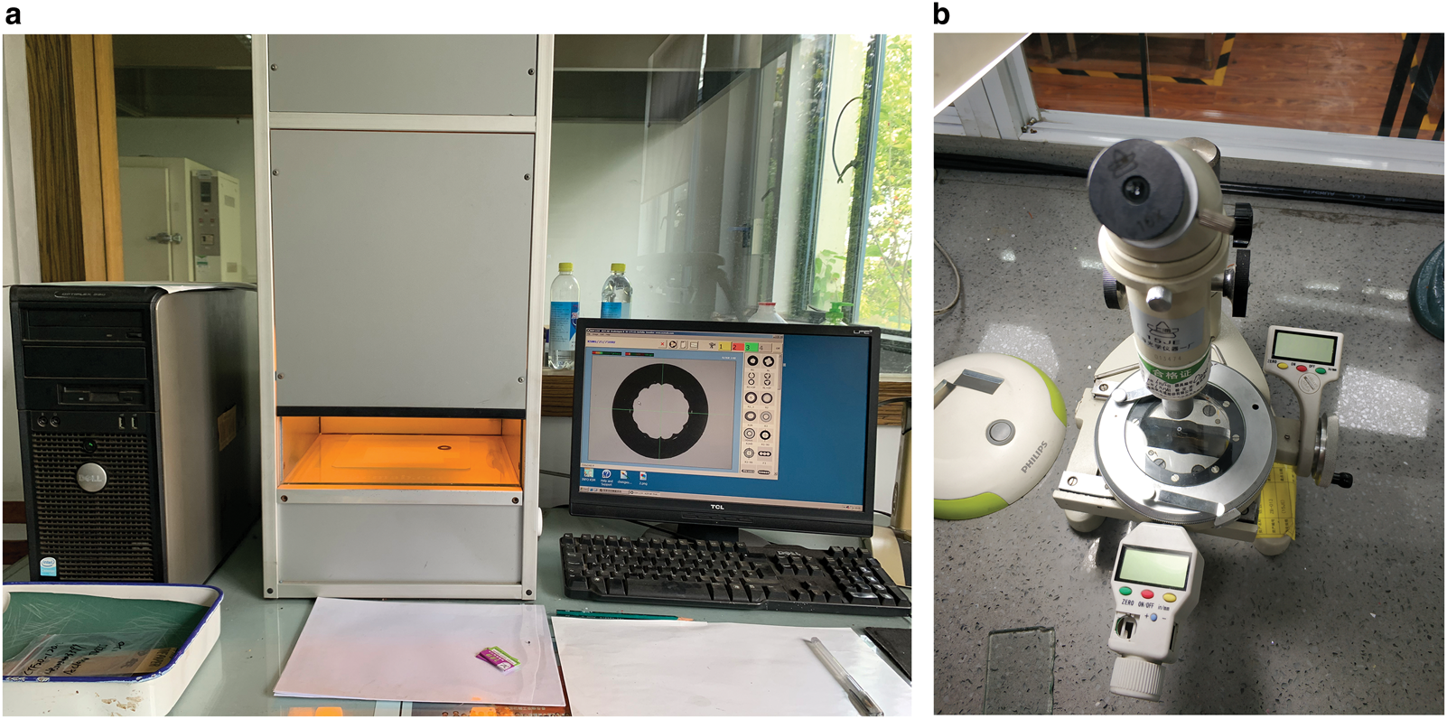
Fig. 1. Testing physical dimensions of cable: (a) profile projector and (b) reading microscope.
3.2. Testing mechanical properties of cable
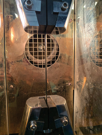
The breaking force is one of the most crucial indexes for a cable's performance. A tensile force test is the first of the mechanical property tests and is performed according to the requirements of IEC 61089-1991. A 2 m long cable specimen is cut out of the manufactured product, and the ends are wound on the two parallel rigid cylindrical shafts (with diameters of 40 mm) of the tensile testing machine (GP-TS2000S/50 kN) with a maximum tensile force of 50 kN (Fig. 2a). Two other shafts in addition to the two winding shafts and clamps are used to fasten the ends. During testing, the two winding shafts are driven apart at a constant rate of 50 mm min−1. The maximum tensile force (breaking force) is measured and recorded during the test using a tension sensor with a measurement accuracy of 0.1 kN (Fig. 2b). Two reference marks are set on the cable specimen, and the distance between these marks is measured during stretching to test the elongation (Fig. 2c).

Fig. 2. Cable breaking force and elongation testing: (a) tensile testing machine, (b) tension sensor and (c) elongation measurement.
Because of the low-temperature working conditions and small bending radius, a test was performed to determine the winding performance and damage propagation in insulation and sheathing layers during cable reeling-in. The testing method is based on IEC 60811-1-4-1985. A 5 m long cable specimen is cut from the manufactured product, wound by hand on the 40 mm diameter drum of a JR-1B warping winch (Fig. 3a) and placed in a pre-cooled low-temperature WD270C-70°C-0°C test chamber (Fig. 3b). The test process is conducted for >2 h under a temperature of −60°C. After the test, the specimen is recovered to room temperature and straightened to inspect the integrity of the outer sheath. Then, the outer sheath is stripped off to check whether there are cracks or fractures in the insulation and inner sealing layers.
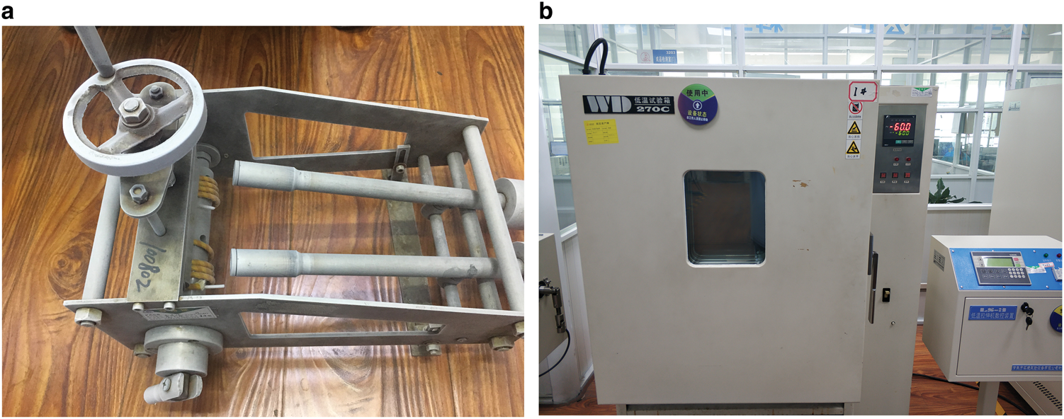
Fig. 3. Low-temperature winding test of cable: (a) low-temperature winding tester and (b) low-temperature test chamber.
3.3. Testing electrical properties of cable
After each batch of cable is processed, a conductor continuity test is carried out using a multimeter to ensure that there is no break in the cable conductors.
The DC resistance of a cable conductor is considered to be one of the main parameters. A certain length (≥1 m) of cable is cut out as a specimen. Before the test, the insulation and sheathing layers are stripped off of two ends, and the specimen is straightened without stretching. The specimen is placed in a room with a stable air temperature of 15–25°C and relative humidity of ≤85% for ~16 h. A DC resistance tester (a Kelvin double bridge with a measurement range of 10−5–1 Ω) with two fixed-resistance terminals is attached to the ends of a conductor of the cable specimen. A schematic circuit diagram of the Kelvin double bridge is shown in Figure 4. The two fixed-resistance terminals have to be kept parallel to each other and perpendicular to the axial direction of the cable. During the test, a DC current that is as low as possible (≤1 A mm−2 of cross-sectional area) is applied to the circuit through the two current terminals of the bridge to avoid the measurement error caused by a temperature rise. Then, the DC resistance of the conductor is measured. The DC resistance testing method is based on the requirements of IEC 60468-1974.
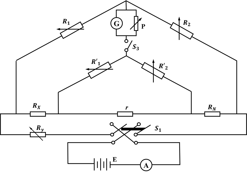
Fig. 4. Schematic circuit diagram of Kelvin double bridge: A, ammeter; E, DC power supply; G, galvanometer; P, diverter; R N, standard resistance; r, link resistance; R y, variable resistance; R 1, R′1, R 2 and R′2, bridge resistances; R X, measured resistance; S 1, DC power switch; S 3, galvanometer switch.
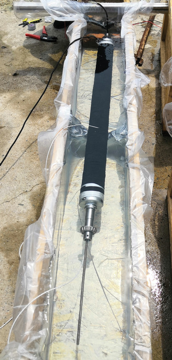
The cross-sectional area of a conductor is related to its current carrying capacity. The current carrying capacity is tested by attaching the cable to the probe in the later joint application test in the lab in accordance with the requirements of IEC 60512-5-1-2002. During the tests, the cable is wound on the drum, and immersed in the bath with water at normal temperature. The maximum operating current is applied through the cable for ~2 h, and the temperatures of the innermost layer of the cable and water temperature are monitored using PT100 temperature sensors, which have a measurement range of −200 to +650°C and measurement accuracy of 0.1°C throughout (Fig. 5). Then, the effect of a temperature rise in the conductor under a high current on the performances of the insulation and sheath material could be determined. Finally, the current-carrying capacity of the conductor is determined.
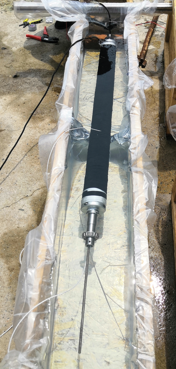
Fig. 5. Cable temperature rise testing in water under maximum operating current.
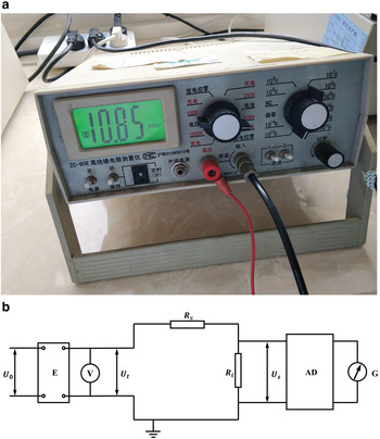
The insulation resistance is a representation of the dielectric strength of the insulation material. A cable specimen with a length of >10 m is cut out, and the sheathing material is stripped off. The specimen is placed in a room with a stable temperature of 15–25°C and a relative humidity of ≤80%. Then, the specimen is placed in water. The ends of two conductors at one end of the specimen are connected to the wire clamps of a ZC-90E type megohmmeter with a measurement range of 105–1014 Ω (Fig. 6a), and the ends of these conductors at the other end of the specimen are separated by 100 mm. Both ends are out of the water by a distance of >250 mm. A 500 VDC voltage is applied to the conductors for 2 min, which allows the insulation resistance to be obtained. The testing circuit is shown in Figure 6b. The testing method for the insulation resistance is developed in accordance with IEC 60885-2-1987.

Fig. 6. Cable insulation resistance testing: (a) megohmmeter; (b) schematic circuit diagram: AD-DC amplifier with high impedance; E, DC power supply; G, galvanometer; R i, input resistance of DC amplifier; R X, insulation resistance of specimen; U 0, AC input voltage; U t, DC output voltage; U s, input voltage drop of amplifier; V, DC voltmeter.
To test the voltage property of the cable, it is placed in a room at normal temperature, and the ends of two conductors at one end of the cable are connected to the high voltage and ground terminals of a GSD-type regulating transformer test stand with a maximum output voltage of 5 kV (Fig. 7). The ends of the two conductors at the other end of the cable are separated by a distance of 100 mm. A testing AC voltage with a frequency of 49–61 Hz is applied to the conductors using the transformer. At the beginning, the test voltage is set to a low level (40% of the withstanding voltage) to avoid the overvoltage effect from the transient voltage. Then, the testing voltage is slowly boosted. When the testing voltage is increased (>75% of the withstanding voltage), the boosting rate is kept at 2% per second (70 V s−1). When the voltage reaches the required 3500 VAC, it is maintained at this value for 5 min to determine whether breakdown occurs. Then, the voltage is gradually reduced to the low level again (40% of the withstanding voltage), and the power supply is switched off. The testing method for the withstanding voltage is developed in according with IEC 60060-1-2010.

Fig. 7. Regulating transformer test stand.
The cable should be able to transmit signals. During the test of carrier wave communication, conductors at both ends of the cable are connected to the signal transmission terminals of two carrier wave devices. Both carrier wave devices send and receive one data package per second (<200 bytes) (both-way communication) with a baud rate of 115 200 to determine the carrier wave communication performance.
3.4. Testing environmental suitability of cable
In consideration of the low environmental temperature and self-heating of the cable during operation, low- and high-temperature tests are carried out to determine its thermal adaptability. The low-temperature test of the wound cable is previously introduced. To test the cable at high temperatures, a specimen is placed in a high-temperature chamber. After heating at 100°C for 2 h, the insulation resistance and withstanding voltage property are tested to determine whether the properties of the insulation material has been influenced by the heating. Then, the two ends of the cable specimen are clamped on two fixtures of a tensile machine that has been placed in the high-temperature test chamber. After heating for 2 h, the tensile machine stretches the specimen at 100°C to determine whether its mechanical properties have been changed by heating (Fig. 8).

Fig. 8. Mechanical property testing under heating.
A 3 m long specimen is used to test the hydrostatic pressure resistance of the cable. First, the sheathing and tensile layers of the cable are stripped off, and the cable is set into a hydraulic press. The two ends of the cable are led out of the pressure chamber through seal terminals and locknuts on the caps of the hydraulic press. Then, 30 MPa of hydraulic pressure is applied by water in the pressure chamber and maintained for 2 h. The water seepage from the ends of the cable is monitored (Fig. 9).
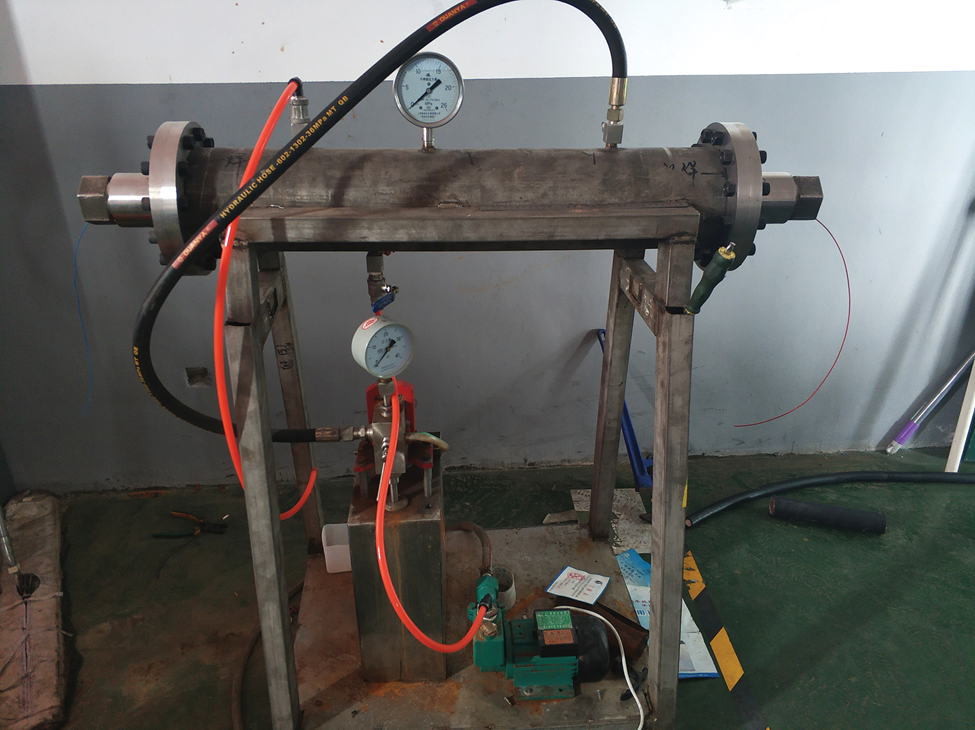
Fig. 9. Cable hydrostatic pressure resistance testing.
4. Cable designs and testing results
Testing and application verification were implemented at each stage of the cable design and processing. If some indexes could not meet the requirements, further improvement and optimization of the cable structure were carried out, attempting to leave the qualified indexes essentially untouched. The four main cable versions considered during the whole design and testing process are presented herein.
4.1. Basic design of cable
4.1.1. Basic structure and materials
A coaxial cable structure with two conductors was adopted. The inner conductor was composed of twisted silver-plated copper wires, and the outer conductor was woven of multi-wire silver-plated copper wires. Polyfluoroalkoxy (PFA) was used as the insulating medium between the inner and outer conductors. It is a material with a good low-temperature performance, and high voltage resistance and mechanical strength properties. It could meet the electrical performance indexes and handle the mechanical stress caused by cable movement at low temperatures.
The outer conductor was wrapped in a tensile reinforcement layer. Because of the high tensile property requirement of the cable, a synthetic fiber (aramid fiber) was adopted, which could effectively improve the tensile capacity of the cable, reduce the cable weight and minimize the cable diameter. Cables armored by Kevlar synthetic fiber were used in the past during electromechanical and thermal drilling in ice and showed reasonable applicability (Schwander and Rufli, Reference Schwander and Rufli1988; Zeibig and Delisle, Reference Zeibig and Delisle1994; Zagorodnov and others, Reference Zagorodnov, Thompson and Mosley-Thompson2000; Zheng and others, Reference Zheng2006); however, there were certain difficulties with Kevlar cables design (Bässler and Kohnen, Reference Bässler and Kohnen1988; Lamont and others, Reference Lamont, Klinck and Wumkes1993).
A sheathing layer shielded the inner members of the cable from the tensile reinforcement layer. Because of the low working temperature of the cable and engineering requirements of wear resistance, erosion resistance and fatigue resistance, several kinds of organic polymer materials were adopted, which could maintain their flexibility in a temperature range of −60 to 100°C.
4.1.2. Main parameter calculations
The cross-sectional areas of the conductors were calculated using the following equations:

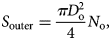
where S inner is the cross-sectional area of the inner conductor; D i is the diameter of the silver-plated copper wire used for the inner conductor; N i is the number of silver-plated copper wires used for the inner conductor; S outer is the cross-sectional area of the outer conductor; D o is the diameter of the silver-plated copper wire used for the outer conductor; and N o is the number of silver-plated copper wires used for the outer conductor.
The DC resistance of the conductor was calculated based on the electrical resistivity of copper at room temperature and the cross-sectional area of the conductor. In this design, the copper wires were plated with silver, which reduced the resistivity of the conductors. The DC resistances of 1000 m long conductors (20°C) were calculated:

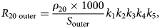
where R 20 are the DC resistances of the conductors at 20°C; ρ 20 is the electrical resistivity of the silver-plated copper wire (0.0157 Ω⋅m); k 1 is the processing technical coefficient (1.07); k 2 is the twisting variation coefficient (1.03); k 3 is the compression coefficient (1.01); k 4 is the twisting resistance increasing coefficient (1.01); and k 5 is the conductor tolerance coefficient (1.01) (the coefficient's values were based on IEC/TR 60344, 2007).
The insulation resistance of an insulating medium is related to the volume resistivity of the insulation material, outer diameter of the insulation layer and outer diameter of the inner conductor. The insulation resistance was calculated as follows:
where R V is the insulation resistance of the insulating medium (PFA); ρ v is the volume resistivity of PFA (1016 Ω⋅m); D is the outer diameter of the insulation layer; and d is the twisting outer diameter of the inner conductor.
The withstanding voltage is the main parameter for ensuring safety when supplying power via a cable. It is calculated using the following equation:
where U is the withstanding voltage value; E is the dielectric strength of PFA under an AC voltage (35 kV mm−1); k id is the effective diameter coefficient of the inner conductor; and k vg is the surface field concentration coefficient of the inner conductor. The effective diameter coefficient was equal to 0.980, determined by the number (37) of copper wires in the inner conductor (Wang, Reference Wang2002). The surface field concentration coefficient of the inner conductor was also determined by the number of copper wires in the inner conductor and was equal to ~1.4 when the number of wires was 37 (Wang, Reference Wang2012).
The breaking force of the cable is one of the key parameters because the cable also acts as a load-carrying member. Theoretically, the breaking force of the tensile reinforcement member is calculated as follows:

where F is the breaking force of the tensile reinforcement member; f is the breaking tension of a single strand of the aramid fiber; n is the number of aramid fiber strands used; and K is the effective utilization rate of the aramid fiber strength.
The tensile capacity of the cable is affected by some other factors during its processing and operation, such as the tensile force correction factor of aramid, woven orientation angle (between a strand and the cable axis) of the aramid bundle and number of aramid strands. The breaking force of the tensile reinforcement member can be precisely calculated as follows:

where k TM is the tensile force correction factor; k b is the factor of the woven orientation angle of the aramid strands; and k a is a factor related to the number of aramid strands.
According to the standard testing method for fabrics, the actual breaking force of the aramid fiber without twisting is 86% of the maximal value of the breaking force (ASTM D 885, 2007), or k TM = 0.86.
The woven orientation angle of the aramid strands influences the overall tensile strength. Because it is difficult to determine theoretically, it is always determined by testing. Based on the results obtained from the naval ocean and development research activity performed at the NSTL station, the overall tensile strength decreases with an increase in the woven orientation angle (Ferrer, Reference Ferrer1980). The presented curves (Fig. 10) make it possible to select the factor for the woven orientation angle of the aramid bundle, k b. This factor decreases with crimp angle in braids, the angle at which fibers deflect from the axis of the weave crossing over each other.

Fig. 10. Reduction of breaking force efficiency depending on woven orientation angle α of aramid bundle at different crimp angles θ of weaving (modified from Ferrer, Reference Ferrer1980).
Furthermore, when the cable is in use, the tensile strength is not evenly distributed among the aramid strands. The number of aramid strands will influence the effective utilization rate of the aramid fiber strength. Based on the test results obtained from the manufacturer using the standard testing method (ASTM D 885, 2007), the utilization efficiency decreases with an increase in the number of aramid strands (Fig. 11). This graph makes it possible to select the factor based on the number of aramid strands, k a. This factor decreases with crimp angle θ in braids, the angle at which fibers deflect from the axis of the weave crossing over each other.

Fig. 11. Reduction of breaking strength depending on the number of aramid strands of Dyneema® fiber (data provided by DSM Limited Company, the Netherlands).
4.2. Cable structures and testing
4.2.1. Cable version #1: CJZ-FKF-2 type
In the initial design stage, a preliminary prototype cable (version #1 of the CJZ-FKF-2 type) was designed according to the basic function of the cable. A total of 37 silver-plated copper wires with a diameter of 0.21 mm were twisted together to form the inner conductor. The cross-sectional area of the inner conductor was determined to be ~1.28 mm2 using Eqn (1), and its diameter after twisting was ~1.47 ± 0.05 mm.
According to Eqn (3), its DC resistance should have been ~13.9 Ω km−1. Hot extrusion molding was used to adhere a 0.5 mm thick PFA layer to the inner conductor. The outer diameter of the insulation layer was ~2.47 mm. The insulation resistance should have been ~8.26 × 10⁵ MΩ⋅km, and the withstanding voltage should have been ~6.98 kV, based on calculations using Eqns (5) and (6), respectively.
Then, 34 silver-plated copper wires with a diameter of 0.22 mm were woven together to form the outer conductor. The cross-sectional area of the outer conductor was calculated to be ~1.29 mm2 according to Eqn (2). Based on Eqn (4), its DC resistance should have been ~14.0 Ω km−1.
A total of 96 aramid strands (Kevlar-49) were woven to form a net structure outside of the outer conductor, to be used as the tensile reinforcement member of the cable. Because the linear density of Kevlar-49 is 1670 dtex, and its tenacity is 20.7 cN dtex−1, the breaking tension of a single strand of Kevlar-49 is 345.7 N. In this design, the tensile force correction factor was 0.86 (ASTM D 885, 2007). The factor for the woven orientation angle (45°) of the aramid strands had a value of 0.51 (see Fig. 10; we expect that crimp angle is 0°), and the factor for the number (96) of aramid strands had a value of 0.72 (see Fig. 11). Thus, the breaking force of the tensile reinforcement member was calculated to be ~10.48 kN using Eqn (8). The thickness of the tensile reinforcement layer was 1.0 mm. A sintering process was used to adhere a 0.5 mm thick layer of perfluoroethylene propylene copolymerization (FEP) to the outside of the aramid. The total diameter of the cable was estimated to be ~6.35 mm. A cross-sectional drawing of cable version #1 is shown in Figure 12a, and descriptions of the structure and dimensions are provided in Table 2.

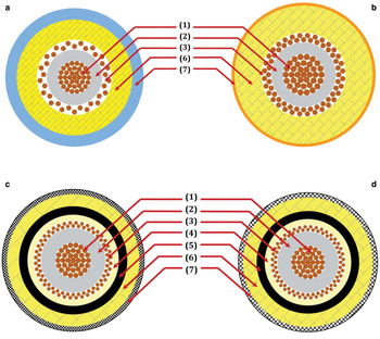
Fig. 12. Cross-sectional schematic drawings of four main versions of cable: (a) version #1, (b) version #2, (c) version #3, (d) version #4, (1) inner conductor (silver-plated copper wires), (2) inner insulation layer (PFA), (3) outer conductor (silver-plated copper wires), (4) outer insulation layer (PFA), (5) sealing layer (polyurethane), (6) tensile reinforcement layer (strength member) (Kevlar in #1, Vectran in #2,3,4), and (7) sheathing layer (FEP in #1, polyimide film in #2, polyamide fabric).
Table 2. Descriptions of structure and dimensions of four main cable versions
A series of tests were performed on prototype cable version #1 (Table 1). The actual measurements showed that the outer diameter of the cable was 6.3 mm; and the DC resistances of the inner and outer conductors were 13.96 and 16.0 Ω km−1, respectively. The withstand voltage and insulation resistance met the specifications, the breaking force was 10.74 kN, and the elongation was 5.5% under a tensile force of 10 kN. Some of the parameters did not meet the requirement indexes, and some other problems were recognized such as a high rigidity and the breakage of the sheathing layer during the application test. In order to decrease the diameter, the amount of aramid was reduced. At the same time, the aramid material and woven orientation angle of the aramid strands had to be optimized to ensure an adequate breaking force and reduce the elongation. In order to reduce the DC resistance of the outer conductor and the cable rigidity, the diameter of the outer conductor and the number of copper wires used had to be improved. In order to prevent the sheathing layer from breaking, a different material had to be selected.
4.2.2. Cable version #2: CJQ-FVP-1 type
Because of the problems discovered with cable version #1, cable version #2 was designed, which was the CJQ-FVP-1 type. The inner conductor had the same design as version #1. The thickness of the insulation layer (PFA) was kept at 0.5 mm. However, 64 silver-plated copper wires with a diameter of 0.18 mm were woven together to form the outer conductor. This made the cable more flexible. The cross-sectional area of the outer conductor was estimated to be ~1.63 mm2, and its DC resistance was ~10.9 Ω km−1. A total of 72 aramid (Vectran) strands were woven together to form a net structure, which was used as the tensile reinforcement member. Decreasing the amount of aramid decreased the cable diameter. A smaller woven orientation angle (22°) and the higher tenacity of Vectran aramid offset the cable tensile capacity decrease due to the decrease in the amount of aramid. Because the linear density of Vectran is 1670 dtex, and the tenacity is 24.6 cN dtex−1, the breaking tension of a single strand of Vectran is 410.8 N. In this design, the same tensile force correction factor of 0.86 was used (ASTM D 885, 2007), the factor for the woven orientation angle (22°) of the aramid strands was 0.84 (see Fig. 10), and the factor for the number (72) of aramid strands was 0.73 (see Fig. 11). Thus, the breaking force of the tensile reinforcement member was estimated to be ~15.6 kN. The thickness of the tensile reinforcement layer was 0.95 mm. A high-strength polyimide film coated with tetrafluoroethylene-hexafluoropropylene copolymer was used as the sheathing layer. During the high-temperature sintering processing, the copolymer was fused and adhered closely to the polyimide material after cooling. The thickness of this layer was ~0.1 mm. The outer diameter of the cable was estimated to be ~5.3 mm. A cross-sectional drawing of cable version #2 is shown in Figure 12b, and descriptions of the structure and dimensions are presented in Table 2.
A series of tests were performed on cable version #2 (Table 1). The measured outer diameter of the cable was exactly as estimated (5.3 mm), and the DC resistances of the inner and outer conductors were 14.1 and 11.2 Ω km−1, respectively. The withstand voltage and insulation resistance were the same as those of cable version #1. The breaking force was 17.27 kN, and the elongation was 3.33%. The breaking force decreased to 16.26 kN after heating to 100°C. In the environmental suitability testing, the members of the cable showed good performances after radial hydrostatic pressurization, heating with bending and freezing with bending. In general, all the technical parameters of cable version #2 met the basic requirements. However, some problems emerged during application tests. The friction between the polyimide and driven capstan wheels of the RECAS thermal probe was too low to drive the cable. This caused the cable to slip during probe movement. Moreover, the polyimide film was easily broken because of the sintering process used during manufacturing. In addition, to ensure safe operation when the cable is in use and prevent an electric leakage hazard due to an accidental system short circuit, the decision was made to add an outer insulation layer to the outer conductor. Further, in order to prevent the infiltration of meltwater between the cable and electrical connectors, the decision was made to add a sealing layer with a high adhesion property to the outer insulation layer. Because of the previously mentioned problems, a new type of sheathing layer and an improved cable structure were proposed.
4.2.3. Cable version #3: CJQ-FVPA-3 type
Because of the revealed problems with cable version #2 and the new requirements, cable version #3 was designed, which was the CJQ-FVPA-3 type. Because additional layers were required, an attempt was made to reduce the thicknesses of the other layers to keep the cable's outer diameter within a reasonable range. The inner conductor and inner insulation layer had the same designs as the previous versions. The thickness of the outer conductor was decreased. This time, 80 silver-plated copper wires with a diameter of 0.15 mm were woven together to form the outer conductor. The cross-sectional area of the outer conductor was estimated to be ~1.41 mm2, and its DC resistance was ~12.6 Ω km−1.
Hot extrusion molding was used to adhere a new 0.35 mm thick PFA layer to the outer conductor as the outer insulation layer. A new polyurethane layer with a thickness of 0.35 mm was formed on the outer insulation layer as a sealing layer because of its good vulcanized property. Fewer Vectran aramid (36) strands were woven together as the tensile reinforcement member. A smaller woven orientation angle (14.2°) could further offset the cable tensile capacity reduction due to the decrease in the number of aramid strands. This design used the same tensile force correction factor (0.86) as the previous versions (ASTM D 885, 2007). The factor for the woven orientation angle (14.2°) of the aramid strands was 0.95 (see Fig. 10), and the factor for the number (36) of aramid strands was 0.75 (see Fig. 11). Thus, the breaking force of the tensile reinforcement member was estimated to be ~9.06 kN. The thickness of the tensile reinforcement layer was 0.5 mm. Because improper materials were selected for the sheathing layers in the previous versions, the sheathing of the cable was redesigned. Polyamide fabric strands were woven together as a sheathing layer with a weaving pitch of 12 mm. The thickness of this layer was 0.2 mm. The total diameter of the cable was estimated to be ~5.9 mm. A cross-sectional drawing of cable version #3 is shown in Figure 12c, and descriptions of its structure and dimensions are summarized in Table 2.
Tests similar to those previously discussed were performed on cable version #3 (Table 1). The measured outer diameter of the cable was 5.9 mm, the same as estimated. The DC resistances of the inner and outer conductors were 13.9 and 12.9 Ω km−1, respectively. There was no change in the withstand voltage and insulation resistance compared with cable version #2. The breaking force was 9.33 kN, and the elongation was 3.04%. In the environmental suitability testing, the members of the cable showed good performances after radial hydrostatic pressurization, heating with bending and freezing with bending. Almost all the technical parameters of cable version #3 met the basic requirements.
During the application test, the friction between the cable and driven wheels of the capstan showed a good performance, and the sheathing layer did not break. However, some problems were discovered. First, although the new sheathing layer provided excellent protection for the inner members of cable, the flexibility of the cable was worse because of the woven structure. After the application test with loading and cable winding, it was difficult to restore the cable to its original state, and the cable easily became unusable and abraded during cable reeling in. Second, the breaking force of this cable version was close to the ceiling limit value, which would make it difficult to guarantee the safe application of the cable during field operation. Therefore, the decision was made to adjust the weaving pitch of the polyamide fabric of the sheathing layer and the number of aramid strands in the tensile layer.
4.2.4. Cable version #4: CJQ-FVPA-5 type
On the basis of the design and practical experience from the previous three versions of the cable, cable version #4 was finally designed as an engineering prototype of the CJQ-FVPA-5 type. The structural design and selected materials were the same as those used in cable version #3 except for the number of aramid strands and the weaving pitch of the polyamide fabric. Thus, the electrical properties and environmental suitability did not change. In the improved design, 48 aramid (Vectran) strands were woven together to form the tensile reinforcement member. The woven orientation angle of 14.2° was maintained. The tensile force correction factor was still 0.86, the factor for the woven orientation angle (14.2°) of the aramid strands was 0.95 (see Fig. 10), and the factor for the number (48) of aramid strands was 0.74 (see Fig. 11). Thus, the breaking force of the tensile reinforcement member was estimated to be ~12.08 kN. The thickness of the tensile reinforcement layer was 0.65 mm.
To improve the sheathing layer, the weaving pitch of the polyamide fabric was increased from 12 to 22 mm. This made the cable more flexible and reduced the thickness of this layer from ~0.2 to ~0.1 mm. The total diameter of the cable was predicted to be ~6.0 mm. A cross-sectional drawing of cable version #4 is shown in Figure 12d, and descriptions of its structure and dimensions are presented in Table 2. Comprehensive multiple parameter tests were performed on this version of the cable (Table 1).
(1) The average outer diameter of the inner insulation layer was 2.53 mm; the average outer diameter of the outer insulation layer was 3.83 mm; the average outer diameter of the sealing insulation layer was 4.49 mm; the average outer diameter of the tensile reinforcement layer was 5.81 mm; and the total diameter of the cable was 6.06 mm. Cross-sectional and side view images of cable version #4 are shown in Figure 13.
(2) A 2 m long cable specimen was used in the breaking force test. The test was repeated three times, and the average breaking force was 12.17 kN. During this test, the average cable elongation under a tensile force of ~10 kN was ~3%.
(3) A 5 m long cable specimen was used for a low-temperature winding test. The specimen was wound on a drum with a diameter of 40 mm and placed in a pre-cooled low-temperature test chamber (−60°C). After 8 h, the specimen was checked. There were no cracks or fractures in the insulation and sealing layers, and the cable exhibited good flexibility.
(4) The DC resistances of the inner and outer conductors were 13.9 and 11.2 Ω km−1, respectively. The withstand voltage and insulation resistance met the required specifications. In the current-carrying and temperature rising test, five layers of cable were wound on the drum, and immersed in water with a temperature of ~25°C. An AC current of 15 A was applied to the cable, and after 140 min, the temperature of innermost layer of cable approached and stabilized at ~80°C. The highest temperature of water was ~50°C. During the carrier wave communication test, two carrier wave devices sent data packages to each other through the cable conductor, and the waveforms could be received at receivers.
(5) The cable specimen was wound up and placed in a high-temperature chamber. After heating at 100°C for 2 h, the insulation resistance and withstanding voltage property were tested and verified to meet the required specifications. The breaking force did not change significantly after heating.
(6) A 3 m long specimen was placed in a pressure chamber (30 MPa). After 2 h, there was no water seepage from the ends of the specimen.
(7) Finally, the weight of the cable was precisely measured and found to be 0.0606 kg m−1.

Fig. 13. Cross-sectional (a) and sideview (b) images of cable version #4 (images have different scales).
5. Conclusions
Intensive research on a new synthetic fiber armored cable for the freezing-in thermal ice probe RECAS has been performed since 2016. Based on the specific electrical, mechanical and environmental requirements of the RECAS probe, the cable should be lightweight and have a high tensile property, a large current-carrying ability, a high voltage withstanding ability, a minor diameter and bending radius, excellent skin wear resistance, and good low/high temperature and hydrostatic pressure resistance performances. Many of these requirements interact with and restrict each other.
This paper outlined the requirements for the proposed new cable, basic technical parameter design, structural design, preliminary prototype design and tests, and engineering prototype improvement and optimization. A series of synthetic fiber armored cables for the RECAS thermal probe were developed and tested. The final version of the cable (version #4 of the CJQ-FVPA-5 type) had the following structure: (1) an inner conductor composed of Ø 0.21 mm × 37 silver-plated copper wires with an outer diameter 1.47 mm; (2) a 0.5 mm thick PFA insulation layer with an outer diameter of 2.47 mm; (3) a concentric conductor composed of Ø 0.15 mm × 80 silver-plated copper wires woven with an outer diameter of 3.07 mm; (4) a 0.35 mm thick PFA insulation layer with an outer diameter of 3.77 mm; (5) 0.35 mm thick polyurethane sealing with outer diameter of 4.47 mm; (6) a load-carrying member composed of 48 strands of woven Vectran (woven orientation angle of 14.2°) with an outer diameter of 5.77 mm; and (7) a polyamide fabric weave (weaving pitch of 22 mm) with an outer diameter of 5.97 mm. The measured outer diameter of cable version #4 was found to be slightly larger than 6.1 mm. The permissible bending radius of the cable was as low as 17–20 mm. The maximal breaking force under straight tension was ~12.2 kN. The cable only weighed ~0.061 kg m−1. The carrying power and current specifications are 12 kW AC/DC and 15 A, respectively. At the same time, two cable conductors could be used for signal transmission.
The mechanical and electrical properties and environmental suitability of the cable were tested through lab testing and joint testing with the RECAS probe. In the near future, the new cable will be used in field tests with the RECAS prototype able to penetrate down to 500 m in a Chinese mountain glacier and then in Antarctica.
To increase the depth of thermal drilling applications down to 2500 m, the cable will be modified in future work to increase its load-carrying capacity and power specifications. In the new design, the cross-sectional areas of the inner and outer conductors will be ~2 mm2, which will allow them to carry a current of 20 A. The number of aramid (Vectran) strands will initially be increased to 72, which will theoretically have a breaking force of more than 17.6 kN. The estimated outer diameter of this cable would be ~7.4 mm. The specific properties of the new cable will be tested in future research.
Acknowledgements
This research was supported by the National Key Research and Development Project of the Ministry of Science and Technology of China (Project No.2016YFC1400302) and the Program for the Jilin University Science and Technology Innovative Research Team (Project No. 2017TD-24). The authors thank the teachers, researchers, engineers and postgraduate students from the participating organizations of this project, who made numerous contributions to the research and testing of the new types of cables. We are grateful to the engineers of Shanghai Qifan Cable Co., Ltd. and the National Centre for Quality Supervision and Test of Electric Wire and Cable of China for their efforts in the cable testing. The authors also would like to thank Scientific Editor O. Alemany (CNRS, Grenoble, France) and two anonymous reviewers for fruitful suggestions and useful comments.


 Open access