


Introduction
Wireless communication technology is considered one of the most rapidly growing industrial markets, where antenna with circular polarization has gained considerable attention in the last few decades. Planar circularly polarized (CP) antennas because of their small size, low profile, economical cost, and easy integrability with handheld devices are widely used in Global Navigation Satellite System (GNSS) receivers, Bluetooth, Radio Frequency Identification (RFID) systems, Wireless Local Area Network (WLAN) applications, etc. CP antennas can reduce multipath fading effects and improve the flexibility in orientation of transmitting and receiving terminals [Reference Long and Sievenpiper1, Reference Sun, Zheng and Liu2]. Some of the widely used navigation systems such as Global Positioning System (GPS), GLONASS, Galileo, Bei Dou Navigation Satellite System (BDS), and Navigation with Indian Constellation (NavIC) make use of L-band (1–2 GHz) antennas with right-hand circular polarization (RHCP) [Reference Babakhani, Sharma and Mishra3, Reference Chen, Wang, Lin, Lin and Pan4]. Based on the type of system, the L-band is further divided into many sub-bands: L5 (1176.45 MHz), L2 (1227.6 MHz), L4 (1379.913 MHz), L3 (1381.05 MHz), and L1 (1575.42 MHz) with ±2% bandwidth requirement. Apart from the frequency constraint, the radiation pattern of the designed antenna should be stable to be employed for navigation.
A conventional method to generate CP radiation entails excitation of two orthogonal current modes of equal magnitude and quadrature phase difference. An alteration in ground surface or radiator will account for this quadrature phase shift in the case of single-feed CP antennas. Another type of antennas identified as dual feed can also be utilized for circular polarization. But the main drawback with dual-feed antennas is that they require an additional feeding circuitry which makes antenna structure difficult to fabricate. A lot of people have proposed many antenna designs with single and dual feed. In reference [Reference Wang and Hisao5], a coplanar waveguide (CPW)-fed asymmetrical ground plane antenna is proposed; a simple antenna with a different arm length is presented in [Reference Ghobadi and Dehmollaian6]. A trapezoidal-shaped monopole structure is proposed in [Reference Augustin and Denidni7], the antenna has multiband radiation behavior. Other wideband CP monopole antennas were proposed using power divider [Reference Kumar and Harish8]; employing four rotated parasitic strips [Reference Wu, Yin and Wang9]; using stacked patches [Reference Kumar, Kanaujia, Khandelwal and Gautam10], etc. However, the main limitations of these reported CP antennas are their large size, limited resonating bands, small axial ratio bandwidth, and complex geometry with external feeding circuitry. Thus, designing a compact single-feed multiband antenna with wide impedance and axial ratio bandwidth is always a challenging task. Microstrip-fed antennas have a drawback in terms of careful alignment of the metallic layer on the two sides of the printed circuit board, which is not suitable for Monolithic Microwave Integrated Circuits (MMIC) fabrication, as a result, the easier device integration is not possible [Reference Gupta, Garg and Bahl11]. The CPW-fed antennas support wide impedance bandwidth and easy device integration using a single metallic layer on the same side of the substrate.
One of the requirements of modern systems like Internet of Things (IoT) is to make use of GPS services as Location of Things (LoT) which will be useful for smarter cities, self-driving cars, detecting luggage, checking thefts, etc. When GPS is integrated with IoT sensors, the exact real-time location of the IoT device can be sensed and insights can be drawn on what, when, and how things are occurring. The tracking of almost every object is possible by combining IoT and GPS system, be it healthcare supplies, important documents, luxurious goods, or anything else. Further, the tracking data need to be transferred to the industry or user by means of wireless systems such as Bluetooth, Wi-Fi/WLAN, or Worldwide Interoperability for Microwave Access (WiMAX) operating in S-band. Therefore, it is desired that the designed system must have the capability to function in both L- and S-bands so that tracking and transmission of information can be achieved [Reference Wu, Wang, Yu, Zhang and Hong12, Reference Pourahmadazar and Rafii13]. In this article, a CPW-fed CP antenna with a rectangular-shaped radiator and ground plane loaded with a wide slot is presented. In the proposed antenna, for generating orthogonal resonant modes of equal amplitude and quadrature phase difference, square-shaped stubs are introduced in the ground plane. According to the simulation results, the proposed antenna has an impedance bandwidth of 123% (1.12–4.72 GHz) and 3 dB axial ratio bandwidth of 11% (1.15–1.29 GHz) and 18% (1.5–1.8 GHz) which can cover L1, L2, L5 frequency-based satellite navigation systems and S-band-based Bluetooth, Wi-Fi, and WiMAX wireless transmission applications. Moreover, by integrating the proposed CP antenna with the commercially available GPS receiver kit, the working of the proposed antenna is also verified in a real environment.
Antenna design
The geometry of the proposed CPW-fed antenna is shown in Fig. 1. The proposed planar antenna consists of a rectangular radiator and a square ground plane with an L-shaped wide slot as shown in Fig. 1(a). The rectangular patch is excited through a 50 Ω CPW feed line and the gap between the ground plane and the feed line is optimized to realize a good impedance matching. Figure 1(b) illustrates the side view of the antenna and the fabricated prototype is shown in Fig. 1(c). The antenna is printed on one side of the FR4 substrate material (ε r = 4.4 and tan δ = 0.04) of dimensions 55 mm × 55 mm × 1.6 mm. The designing and optimization of the proposed antenna dimensions are completed by means of a commercially available CST Microwave Studio tool. The optimized designing parameters are given in Table 1.
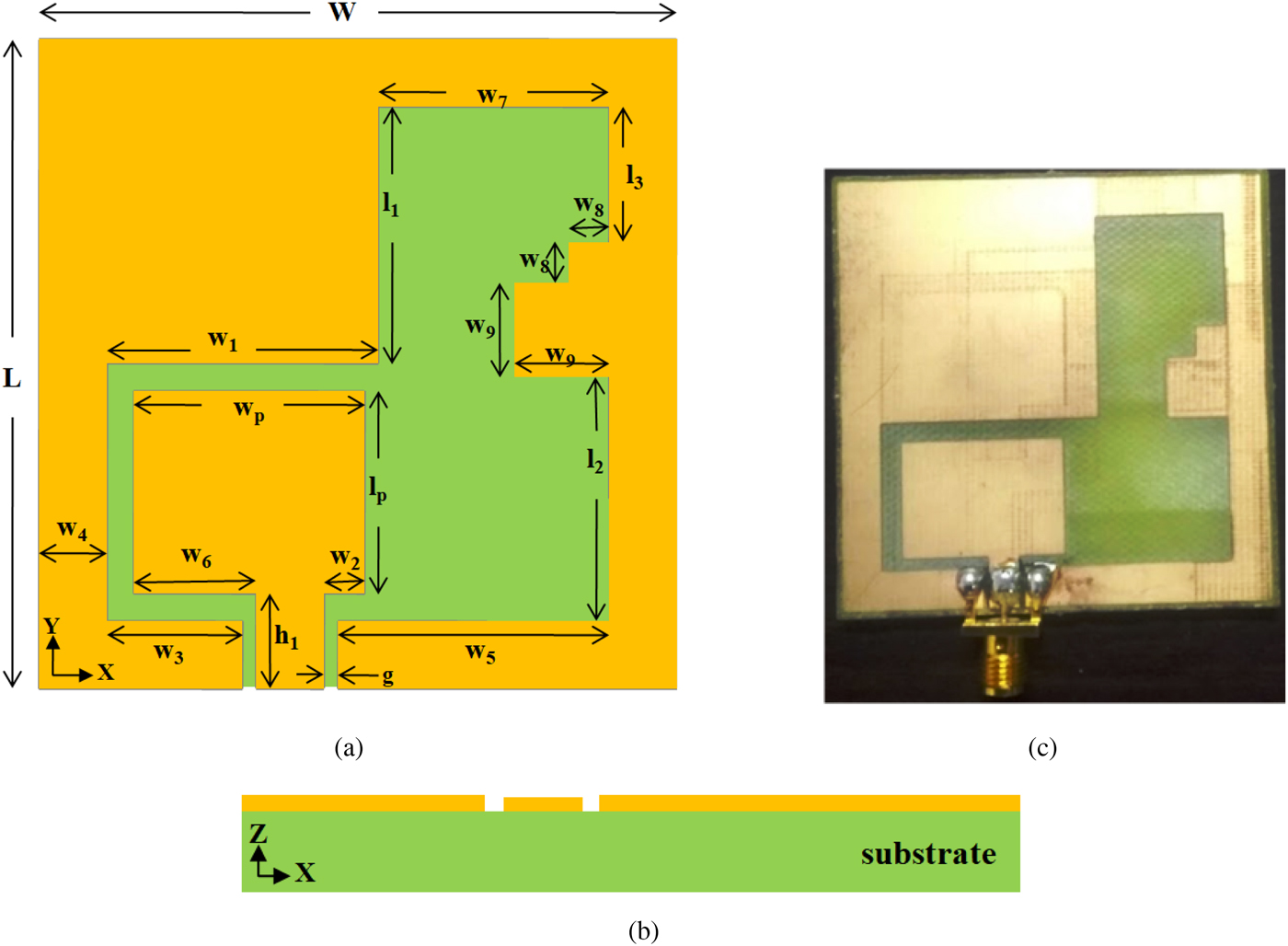
Fig. 1. Geometry of the proposed antenna: (a) top view, (b) side view, (c) fabricated prototype.
Table 1. Dimensions of the proposed antenna
To better understand the design procedure, the evolution of the proposed antenna is demonstrated in Fig. 2. Figure 3(a) illustrates the S 11 characteristics of antenna designing steps and the axial ratio behavior is shown in Fig. 3(b). The antenna shown in Fig. 2(a) (Ant. 1) is a typical CPW-fed rectangular patch radiator with a wide square slot loaded in the ground plane. The introduced wide slot increases the impedance bandwidth of the antenna, but due to improper impedance matching, less amount of radiation is seen. The designed Ant. 1 radiates linearly polarized waves. Further, to improve the impedance matching in the proposed structure, Ant. 2 is designed as shown in Fig. 2(b), in which the main radiator and feed line are shifted toward the left side of the ground plane. This change in the position of the radiator improves the radiation characteristic of the antenna and a small improvement in the axial ratio value is also seen. In the next step, by means of loading, a wide square stub is integrated with the ground plane of the antenna toward the left side (Ant. 3) as illustrated in Fig. 2(c). This improves the impedance bandwidth of the antenna in the lower frequency range and two narrow 3 dB axial ratio bands at 1.3 and 2.3 GHz are also seen. Then, in Fig. 2(d), two square-shaped stubs are integrated with the right edge of the ground plane of the proposed Ant. 3. These introduced square-shaped stubs improve the 3 dB axial ratio bandwidth of the proposed design (Ant. 4) significantly, without changing much the impedance bandwidth of the antenna.
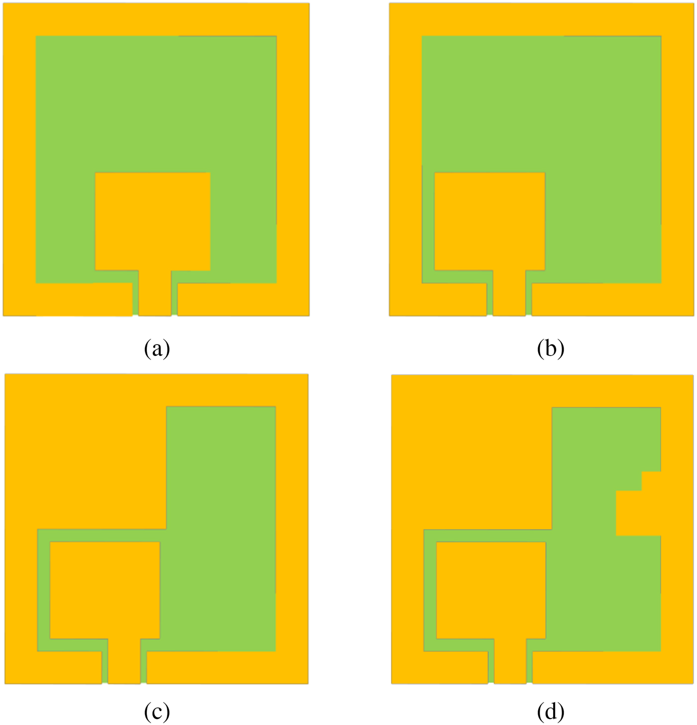
Fig. 2. Evolution steps of the proposed antenna: (a) Ant. 1, (b) Ant. 2, (c) Ant. 3, (d) Ant. 4.
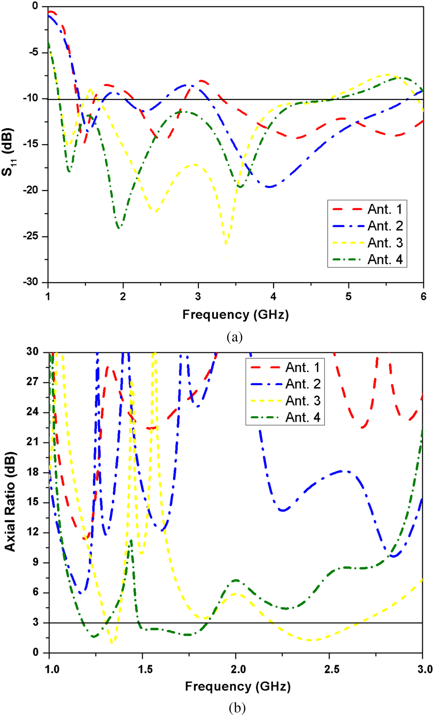
Fig. 3. Performance comparison of antenna designing steps: (a) magnitude of S 11, (b) axial ratio.
Results and discussion
The antenna is fabricated with the help of the photolithography method, and the measurements are performed using Keysight N5227A vector network analyzer. The simulated and measured reflection coefficient characteristics of the proposed antenna are shown in Fig. 4. The measured impedance bandwidth of the antenna is around 3.4 GHz from 1.3 to 4.7 GHz, which is 113% with a central frequency of 3 GHz. The lower cut-off frequency of the measured S 11 slightly shifts to the upper side compared with the simulated, which was 123%, this may be due to the fabrication tolerance, soldering loss, and cable effects. The simulated and measured 3 dB axial ratio bandwidth is found to be 11% (1.15–1.29 GHz) and 18% (1.5–1.8 GHz) as shown in Fig. 5 corresponding to w 9 = 8 mm, which could be useful for GPS applications in L1 (1575.42 MHz), L2 (1227.6 MHz), and L5 (1176.45 MHz) bands. Figure 6 shows the simulated and measured boresight gain level, which is varying from 1.5 to 2 dBi in the 3 dB axial ratio bands and around 2.3 dBi at 2.45 GHz.
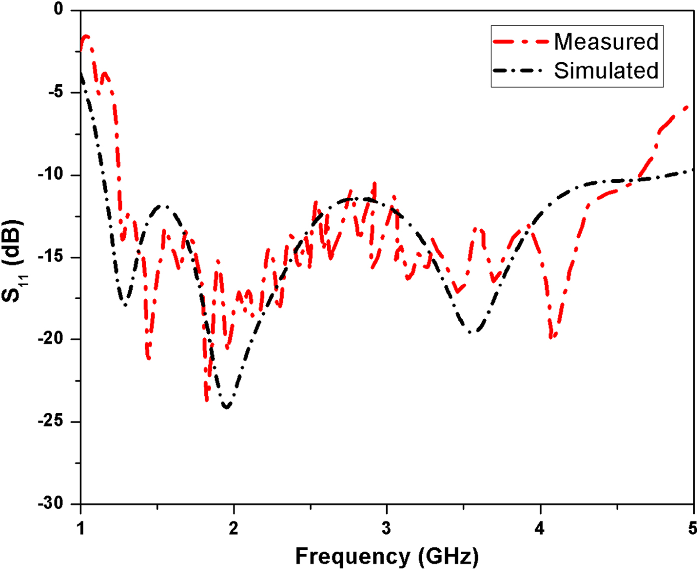
Fig. 4. Simulated and measured S 11 of the proposed antenna.
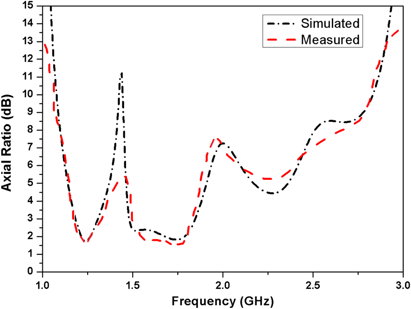
Fig. 5. Simulated and measured axial ratio of the proposed antenna.
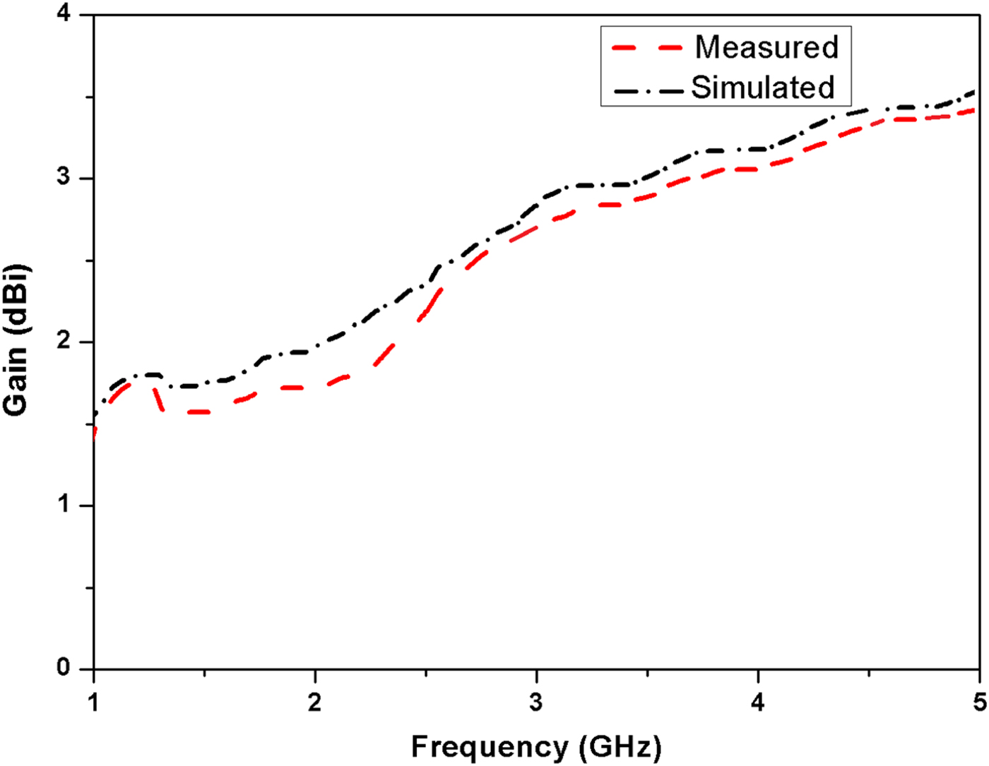
Fig. 6. Simulated and measured gain of the proposed antenna.
In Fig. 7, the surface current distribution of the proposed CP antenna at 1.58 GHz at four different time instants: ωt = 0°, 90°, 180°, and 270° is shown. The current distribution when viewed from the +Z direction symbolizes how circular polarization is generated from the designed antenna. The results in the figure show that the dominant horizontal and vertical current components give rise to synthesized currents which are orthogonal to each other thus showing an anti-clockwise behavior over time. The field radiated by the antenna is RHCP in the +Z direction and left-hand circular polarization (LHCP) in the –Z direction. This property of the antenna is useful for polarization diversity-based applications to overcome the effects of multipath fading. Figure 8 shows the simulated and measured radiation pattern of the proposed antenna at 1.17, 1.22, and 1.58 GHz in XZ- and YZ-planes. As seen from the radiation pattern, the proposed antenna radiates RHCP waves toward the upper hemisphere and LHCP waves toward the lower hemisphere with a stable pattern.
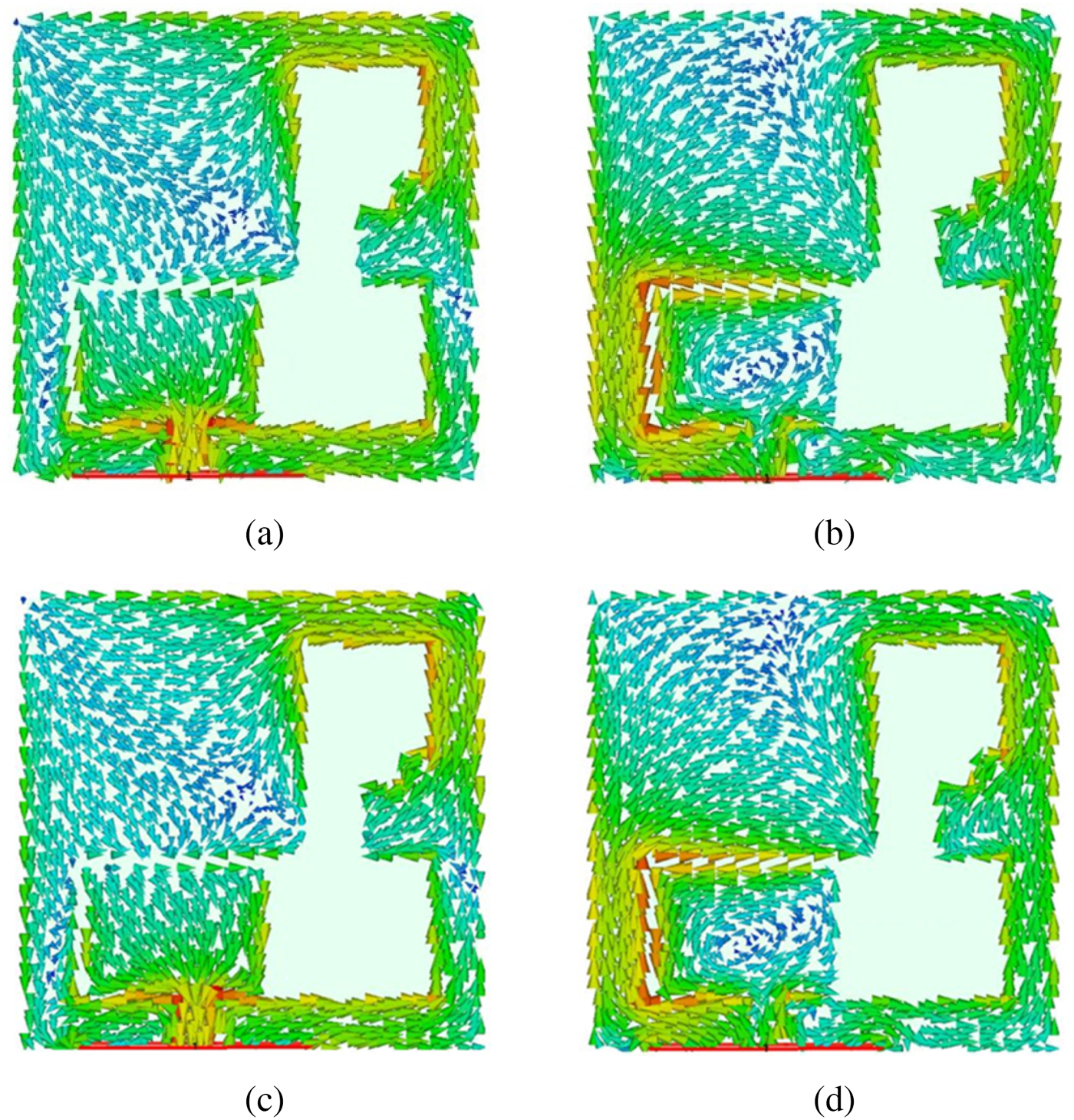
Fig. 7. Current distribution of the proposed antenna at 1.58 GHz: (a) ωt = 0°, (b) ωt = 90°, (c) ωt = 180°, (d) ωt = 270°.
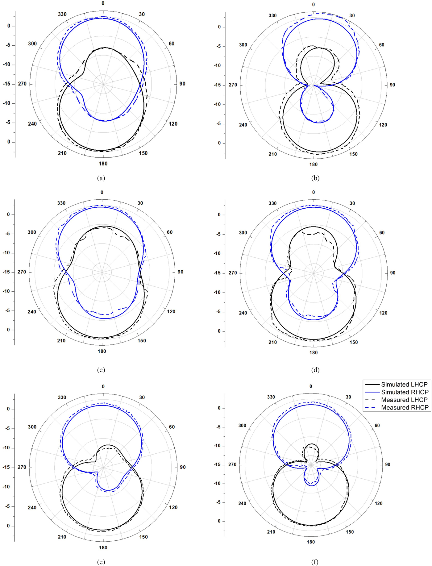
Fig. 8. Radiation pattern of the proposed antenna: (a) 1.17 GHz, XZ-plane; (b) 1.17 GHz, YZ-plane; (c) 1.22 GHz, XZ-plane; (d) 1.22 GHz, YZ-plane; (e) 1.58 GHz, XZ-plane; (f) 1.58 GHz, YZ-plane.
Parametric analysis
This section presents the design analysis of the proposed CP antenna by varying different design parameters. For this study, one of the antenna design parameters is altered while keeping other dimensions fixed and its impact on the antenna performance is noticed. The simulated results of S 11 and axial ratio are shown in Figs 9 and 10 for different values of w 1 and w 9, respectively. A significant change in S 11 is seen when the value of w 1 is altered from 24 to 28 mm (Fig. 9), this impacts the antenna matching with some improvement in the axial ratio bandwidth. This is due to the size of w 1, which changes the input impedance of the ground plane, which affects the main radiator matching. Using this comparison, the optimized value for w 1 is considered as 26 mm for designing the proposed antenna. The square stub side w 9 integrated at the right part of the ground plane shows an impact on the axial ratio bandwidth as illustrated in Fig. 10. In Fig. 10, as the length of w 9 is increased from 6 to 8 mm, a reasonable improvement in the axial ratio in the GPS band (L1, L2, and L5) is seen. On further increasing w 9 to 10 mm, a decrement in the axial ratio value is observed. Hence, it can be concluded that the best results are achieved at w 9 = 8 mm and w 1 = 26 mm.
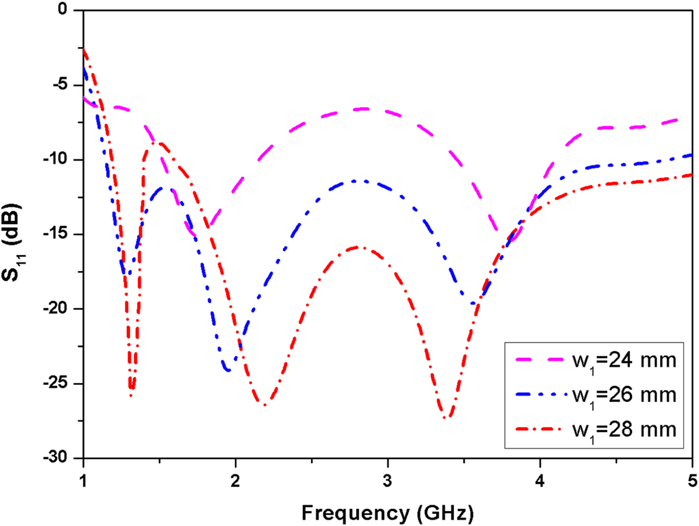
Fig. 9. Simulated S 11 with different values of w 1.
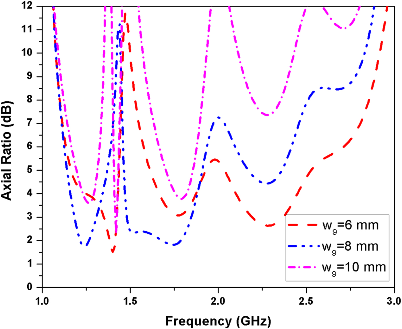
Fig. 10. Simulated axial ratio with different values of w 9.
Antenna integration with L1 band GPS receiver
In this section, the proposed antenna is integrated with a commercially available GPS receiver and tested in the real environment. For the testing purpose, the SIM868 development board GSM/GPRS/Bluetooth/GPS module with two antennas is used (https://www.banggood.com/SIM868-Development-Board-GSM-GPRS-Bluetooth-GPS-Module-With-Two-Antenna-p-1159415.html). The module SIM868 supports both GSM/GPRS and GNSS technology intended for satellite navigation (http://simcomm2m.com/En/module/detail.aspx?id=145). The module has two antenna interfaces, one for GSM and other for GPS, and to uphold simplicity in this study, only one antenna port (GPS port) has been used. Figure 11 shows the experimental setup of SIM868 development board which is serially connected to the Arduino nano microcontroller based on ATmega328P (https://store.arduino.cc/usa/arduino-nano). This helps in sending various AT commands to SIM868 module; by means of these AT commands, one can easily control the functioning of this module. Figure 11(a) represents the complete setup which is made to receive GPS signals at L1 band by means of a standard antenna. As can be seen in Fig. 11(a), the available standard antenna is connected with the SIM868 development board through an SMA connector. The white cable establishes a serial connection between the Arduino nano microcontroller and SIM868 module for the transmission and reception of information. A power bank with a rating of 5 V/1 A is used for providing power to both the modules. Once the setup is ready, the sequence of AT commands can be easily executed (for obtaining the GPS coordinates of any location) using the laptop which is connected to Arduino nano microcontroller through the USB port.
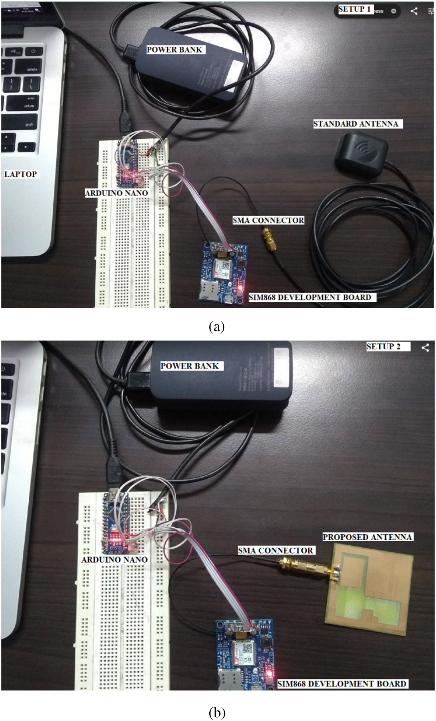
Fig. 11. Experimental setup of standard GPS receiver: (a) commercially available antenna, (b) proposed antenna.
The first command used to open the GPS system is “AT + CGPSPWR = 1”. Further, the command “AT + CGPSSTATUS?” is used to locate the current status of the GPS. A GPS generates several responses in the form of a string; a few of the standard responses are “Location unknown” which means GPS is not running; “Location not fix”, it appears when GPS is running but the location is not fixed. The responses “Location 2D fix” and “Location 3D fix” illustrate the test environment that GPS is capable of receiving either 2D data or 3D-based location information. These commands need to be executed multiple times since the GPS requires some time to initialize and fix the status. Once the location of GPS is set, the data can be easily generated using the “AT + CGPSOUT = 32” command, as an output on the screen. The location-based data provided by GPS is in the National Marine Electronics Association (NMEA) format which is a standard data format supported and accepted by all GPS manufacturers globally. For the setup shown in Fig. 11, the location-based data were obtained and represented in the first (with standard antenna) and second (with proposed antenna) columns of Table 2.
Table 2. NMEA message format
Moreover, a sequence of AT commands was executed, without changing the location and the data are obtained as shown in Table 2. For the easy operation and understanding, the data need to be converted into a standard format which can be used in the map; usually, the formats accepted are degrees and decimal minutes and decimal degrees (DD). In this work, the DD format is selected and the location obtained by the setup shown in Fig. 11(a) is latitude: 28.5850523833 and longitude: 77.16306891667. Further to this, the location of the setup shown in Fig. 11(b) is also calculated; latitude: 28.5854148833 and longitude: 77.1630545667. The obtained location data are then uploaded in the Google map application to find the location on the map (as a satellite view). The correct location can be identified by using latitude and longitude data through Google maps (https://support.google.com/maps/answer/18539?co=GENIE.Platform%3DDesktop&hl=en). Figures 12(a) and 12(b) represent the respective locations (with the help of red color mark) and it is observed that the distance calculated by using setup 1 (standard antenna) is 36.74 and 22.61 m with setup 2 (proposed antenna). In both the cases, the distance was calculated by keeping the same reference location, and for this experiment, this reference location considered was the current location, given by Google maps where the experiment was performed (marked with a white dot in Fig. 12). Now, from this reference location, the two distances are calculated; given by commercially available antenna and proposed antenna. The designed setup could be helpful in the integration of the proposed antenna with L1 band GPS receiver. Due to the broadband characteristics of the proposed antenna, a similar setup can be made to evaluate the antenna performance at other GPS bands also.
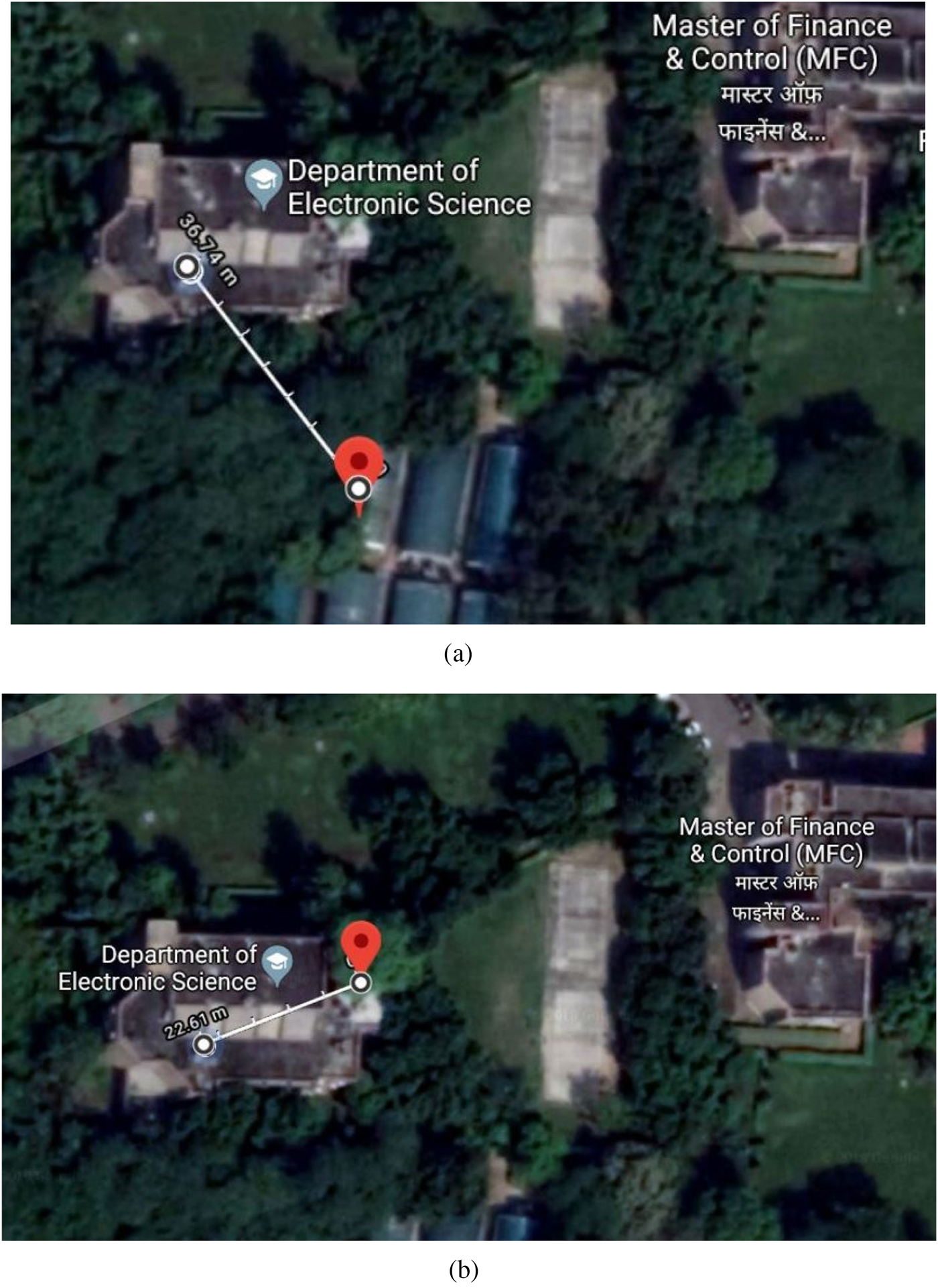
Fig. 12. Satellite view with calculated distance by Google maps: (a) commercially available antenna, (b) proposed antenna.
Table 3 compares various characteristics of the proposed antenna with the previously reported antenna structures based on CPW feed technique [Reference Wang and Hisao5, Reference Sze and Ou14–Reference Zheng, Lai and Wang24]. The antennas proposed in [Reference Wang and Hisao5, Reference Sze and Ou14, Reference Zheng, Lai and Wang24] provide RHCP radiation and has a narrow axial ratio bandwidth suitable for GPS L1 band only; they do not cover other lower frequency bands (L2 and L5). The designs presented in [Reference Pouyanfar and Azarmanesh15–Reference Zhai, Yang, Xi and Feng23] provide a wider axial ratio bandwidth and are suitable for WLAN, WiMAX, and RFID applications. Comparatively, the proposed CPW-fed antenna covers lower frequency bands and has the advantage of compact size, wide impedance, and axial ratio bandwidth. A broadband design is chosen in contrast to multiband antenna structure due to the fact that broadband antennas usually present better radiation pattern symmetry and higher polarization purity [Reference Li, Guo, Dai and Fu25], which improves the location accuracy of the antenna in L1, L2, and L5 satellite bands.
Table 3. Comparison of proposed CPW-fed antenna with other reported antennas
Conclusion
In this paper, a CPW-fed wide slot antenna with circular polarization and wide impedance bandwidth is presented. By introducing several stubs in the ground plane of the proposed antenna, a broad impedance and an axial ratio bandwidth are achieved. The designed antenna shows −10 dB impedance bandwidth of 123% (1.12–4.72 GHz) and 3 dB axial ratio bandwidth of 11% (1.15–1.29 GHz) and 18% (1.5–1.8 GHz). The proposed antenna occupies a total volume of 55 mm × 55 mm × 1.6 mm and could be suitable for GPS (L1, L2, L5 bands), Bluetooth, Wi-Fi, and WiMAX-based L- and S-band wireless applications.
Author ORCIDs
Binod Kumar Kanaujia, 0000-0003-1272-1561
Acknowledgement
The present work is performed under the Research & Development scheme 2015–16 of the University of Delhi (RC/2015/9677, dated 15/10/2015).
 Amit Birwal received his M. Tech. degree in Microwave Electronics from the University of Delhi in 2006 and the B. Tech. degree in Electronics and Telecommunication Engineering from Guru Gobind Singh Indraprastha University, Delhi in 2003. He worked at various levels in the development and test phases of telecom devices at Ericsson India. He now holds a position of Assistant Professor at the Department of Electronic Science, University of Delhi South Campus, India. His main research interests are the design and optimization of planar antennas for IoT-based systems.
 Sanjeev Singh has worked in the area of optical electronics and had obtained his Doctorate in Electronics in 1997 from the University of Delhi. He holds a position of Associate Professor at the Institute of Informatics and Communication, University of Delhi and has published more than 50 research articles in various international/national journals and conferences. He is a Fellow of EU-India Cross Cultural Innovation Network. His current research areas are IoT-based system design, security models, and cyber-physical system.
 Binod Kumar Kanaujia received his B. Tech. degree in Electronics Engineering from Kamla Nehru Institute of Technology, Sultanpur, India in 1994. He did his M. Tech. and Ph.D. in 1998 and 2004, respectively, from the Department of Electronics Engineering, Indian Institute of Technology Banaras Hindu University, Varanasi, India. At present, he is working as a Professor in the School of Computational and Integrative Sciences, Jawaharlal Nehru University, New Delhi, India. He has been credited to publish more than 250 research papers with more than 1200 citations and h-index of 18 in several peer-reviewed journals and conferences. He had supervised 50 M. Tech. and 15 Ph.D. scholars in the field of RF & microwave engineering. He is currently on the editorial board of several international journals. Dr. Kanaujia had successfully executed five research projects sponsored by several agencies of Government of India, i.e. DRDO, DST, AICTE, and ISRO. He is also a member of several academic and professional bodies, i.e. IEEE, Institution of Engineers (India), Indian Society for Technical Education and The Institute of Electronics and Telecommunication Engineers of India.
 Sachin Kumar received his B. Tech. degree in Electronics and Communication Engineering from Uttar Pradesh Technical University, Lucknow, India, in 2009. He received his M. Tech. and Ph.D. degrees in Electronics and Communication Engineering from Guru Gobind Singh Indraprastha University, Delhi, India, in 2011 and 2016, respectively. At present, he is working as a Researcher in the School of Electronics Engineering, Kyungpook National University, Daegu, Korea. His research interest includes circularly polarized microstrip antennas, reconfigurable antennas, ultra-wideband antennas, defected ground structure, and microwave components.


